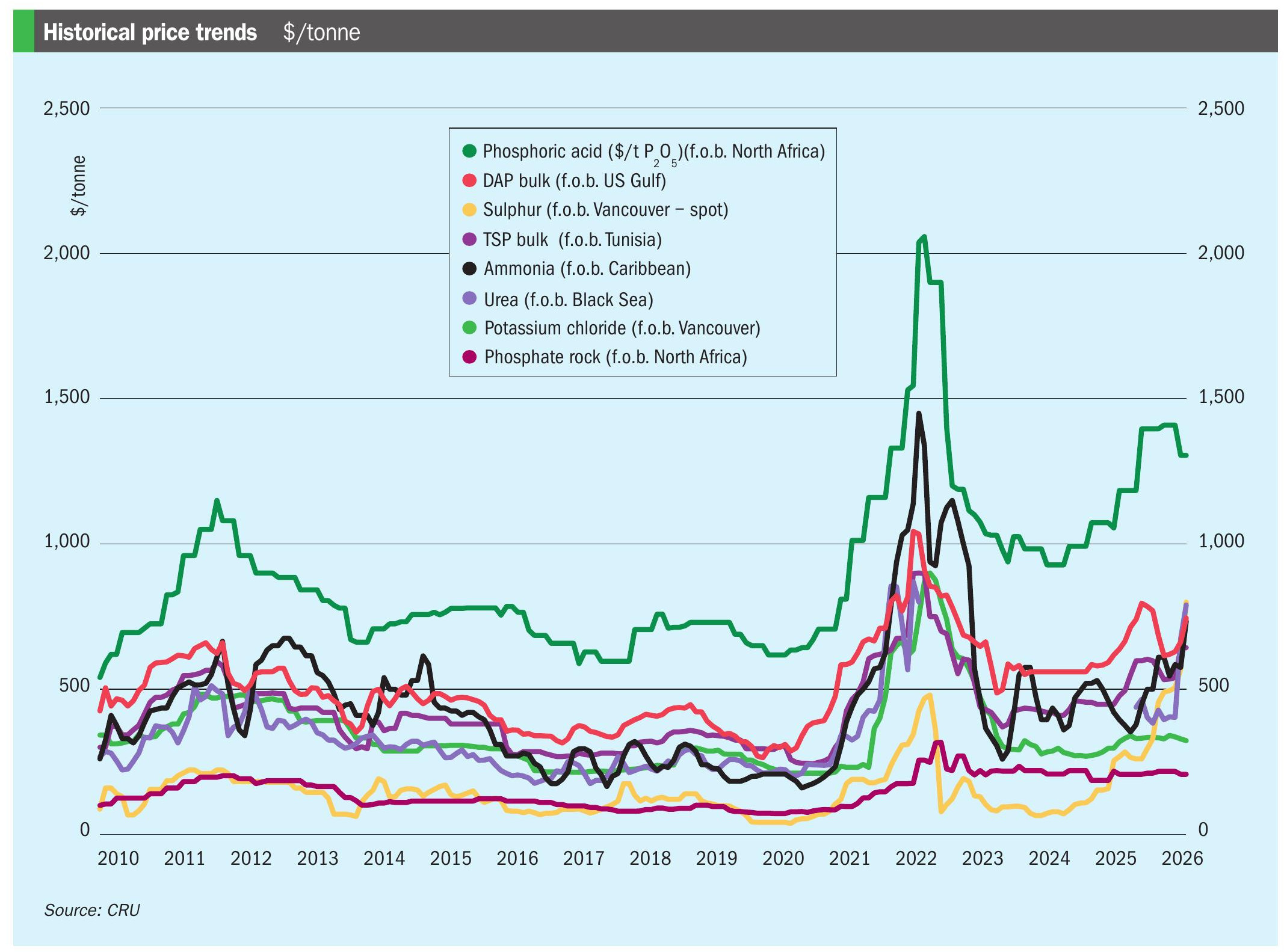
Nitrogen+Syngas 363 Jan-Feb 2020
31 January 2020
Ammonia plant upgrade and purge gas recovery
AMMONIA PLANT DEBOTTLENECKING
Ammonia plant upgrade and purge gas recovery
Cryogenic purge gas recovery units are very tolerant to increased flow from ammonia plant debottlenecking, especially the cryogenic cold box section. However, overload of the dehydration system upstream of the cold box can lead to fouling, loss of hydrogen recovery performance and the need for costly shutdown and thaw. Awareness of key plant parameters and some simple precautions can avoid such problems. A. J. Finn and T. R. Tomlinson of Costain provide some guidance.
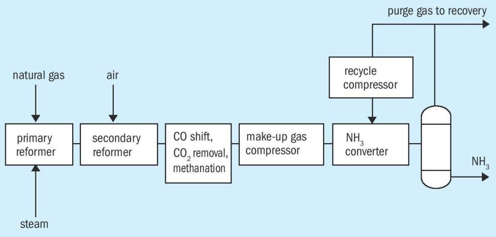
Ammonia plant purge gas recovery units (Figs 1 and 2) recover both ammonia and hydrogen, leading to increased energy efficiency (by about 0.7 GJ/tonne ammonia). Typically, this reduced specific energy has enabled as much as 4-5% more ammonia production. Overall ammonia plant optimisation might increase this even more.
Cryogenic hydrogen recovery is common on larger ammonia plants (1,500 t/d and above) due to higher hydrogen recovery at high inerts (argon and methane) rejection than with semi-permeable membranes and because all hydrogen is recovered at high pressure, thus saving on the cost of compression to synthesis gas pressure. Cryogenic units have great flexibility for variable purge gas flow, as shown by the fact they can recover up to 60% nitrogen if required. Many smaller hydrogen recovery units also use cryogenic technology. Costain has installed about 40 such cryogenic units on ammonia plants to help clients reduce their energy use.

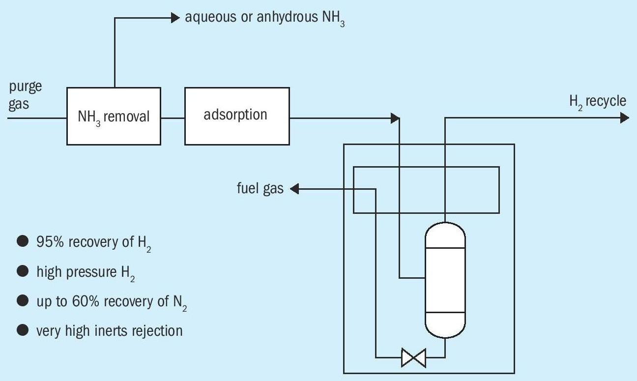
A cryogenic unit’s ability to cater for high purge gas flow enables the ammonia synthesis loop to be operated at low inerts levels, to increase hydrogen and nitrogen conversion to ammonia. Normally, if the purge gas inerts level is maintained at about 10% or more (ammonia-free basis), the cold box can operate at a low enough temperature to achieve both high hydrogen recovery (95%) and high inerts rejection, even at up to 50% of nominal design capacity.
A cryogenic unit helps ammonia plant performance substantially if either the primary reformer or the process air compressor are bottlenecks. Increased methane slip from the primary reformer, as gas flow increases, is easily accommodated. By increasing cold box separator temperature, nitrogen recovery can be increased from less than 30% to about 60%, so as to work around process air compressor limitations and increase secondary reforming.
The ability of cryogenic units to maintain high hydrogen recovery, have operational flexibility, be energy efficient, simple to operate and have very high reliability is all well known by plant operators 1 . It may thus be considered from operational experience that a purge gas recovery unit needs little attention, even for a major ammonia production upgrade. However, in planning such a capacity increase, a process engineering assessment of each section of the purge gas recovery unit is needed – ammonia recovery and regeneration, feed gas pre-treatment and the cold box. Any limitations can often be dealt with by relatively small plant modifications. The effect of increased purge gas on these three sections will be considered in turn.
Cold box
The cryogenic separation relies on there being sufficient inerts in the purge gas to provide Joule-Thomson refrigeration and maintain energy-efficient auto-thermal operation. The cold box contains one or more multistream aluminium plate-fin heat exchangers and normally just one phase separator, though there may be a second separator to give medium pressure hydrogen and very high hydrogen recovery 2 . High purge gas flow leads to high separator vapour velocities. Separators are normally designed with a suitable margin. Ultimately, at flows of over 30% above those used for vessel sizing, they would incur liquid entrainment, but any effect from this on hydrogen purity and overall cold box performance would be small.
Plate-fin heat exchangers are very accommodating to increased flows as overall heat transfer coefficient increases with flow to the power of about 0.7. Therefore a heat exchanger with 20% thermal margin can cope with a 50% increase in feed gas flow and maintain design performance, as long as the pressure drops are tolerable. This can be verified by rigorous exchanger rating. Therefore cold box performance is not normally a big consideration, especially if the temperature of the feed gas to the cold box can be reduced.
Pipework pressure drops have to be reviewed and the trim of the cold box level control valve to fuel gas may might need changing to minimise pressure drop. However, any physical changes should be minimal. Thus the cold box would not typically be a bottleneck to increased purge gas flow.
Ammonia recovery and regeneration
Ammonia recovery uses ammonia absorption in a lean solution (of water of very low ammonia content) obtained from the downstream rich solution regeneration. The ammonia absorber is typically designed at a relatively low approach to flood to minimise it being a bottleneck. How much the purge gas flow could be increased would need assessment of the installed packing performance. A modern packing could better provide sufficient surface area for vapour-liquid contact whilst reducing pressure drop with lower approach to jet flood. Potentially much more purge gas could then be processed without reaching hydraulic limits and without needing to change the absorber vessel. In some circumstances no change would be needed to the column packing even for much increased purge gas flow.
The ammonia regeneration system is mostly influenced by the ammonia-water solution flow. Lean solution flow to the ammonia absorber might need increasing in direct proportion to the purge gas flow (assuming the same purge gas ammonia content) to avoid excessive absorber operating temperatures. However, the lean solution flow specified for design would be based on sufficiently wetting the absorber packing, so increased purge gas flow may not actually need an increase in lean solution flow. This could be easily checked and reviewed.
If lean solution flow did need to be increased the ammonia regeneration system could be a bottleneck. The individual equipment items of the regeneration system would need checking, especially pumps and the regeneration column capacity. Higher lean solution flow would need to be checked against pump capacity. Changes to pump motors might be avoided. As with the absorber, modern packings may provide more regeneration column capacity with no loss of separation performance.
The main duty of the regeneration system is to provide lean solution of sufficiently low ammonia content (typically 1%) to the ammonia absorber at low temperature. Therefore if the lean solution were water-cooled (to achieve low treated gas temperature from the absorber), the performance of the relevant cooler would need checking to ensure the required lean solution temperature could be met for higher flow.
It would be beneficial to reduce the ammonia content of the purge gas feed to the ammonia absorber, typically by increased chilling of the purge gas upstream. A lower lean solution flow would then suffice. A reduction of say 25% from e.g. 2 mol-% to 1.5 mol-% ammonia would mean the lean solution flow could be decreased by at least 25%. This could be easily assessed by process simulation, properly taking into account the heat release as ammonia dissolves into solution, the effect on absorber operating temperatures and on ammonia volatility. A plant model could be aligned with known performance and benchmarked to help identify equipment margins e.g. on regeneration column packed height.
The ammonia recovery and regeneration systems could thus be assessed and any changes identified from site operating data, process simulation and review of equipment limits, including column hydraulics and whether new packing would be of benefit. As with all upgrade projects, pipeline fittings and instruments would need checking, including flowmeter rangeability and thermowell vibration. Two phase lines in particular would need checking for vibration.
Cold box pre-treatment
The water and ammonia in the treated gas from the ammonia absorber must be removed prior to the cold box. This is achieved by the molecular sieve adsorber system. Two molecular sieve containing vessels are employed with one always in operation removing water and ammonia. After a specific on-line time this vessel is thermally regenerated, by heating it to about 200°C, whilst the other freshly regenerated adsorber vessel is in operation. The permitted level of water and ammonia in the cold box feed is negligible and good adsorber operation is essential.
Increased purge gas flow may also lead to increased treated gas temperature and therefore increased purge gas water and ammonia content, so that the adsorption duty is much increased. The adsorber system could be overloaded, with ammonia passing to the cold box. It would not be obvious this is happening.
Some operators believe that freezing can be detected by increased cold box pressure drop. This is unlikely. Freezing would occur on the feed gas passages of the aluminium plate-fin exchanger, reducing heat transfer performance and thus making it difficult to achieve the desired cold box separator temperature (typically about –180°C). Therefore unexplained increase in cold box separator temperature is a good indicator of freezing.
Less feed gas condensation from reduced exchanger capacity means less liquid being formed, and as liquid let-down in pressure provides critical process refrigeration (by the Joule-Thomson effect) so freezing ultimately means insufficient refrigeration for the cold box to operate satisfactorily. Insufficient removal of ammonia (and possibly water) in the adsorber system would therefore be potentially very significant – leading to poor inerts rejection, increased purge gas flow to counteract this effect, further cold box contamination due to high purge gas flow, and so on.
“A properly assessed capacity upgrade of a cryogenic purge gas recovery unit can ensure excellent performance is maintained.”
Unforeseen cold box contamination would ultimately necessitate cold box shutdown, thaw-out and cool down. This procedure may take several days. The plate-fin heat exchanger would need to be warmed, properly thawed, all contaminants removed and then cooled down in line with ALPEMA 3 limitations. Doing this too quickly may lead to thermal stressing of the heat exchanger, loss of mechanical integrity and leaks. Whilst simple exchanger leaks can be repaired, this would require complete emptying and refilling of the cold box insulant and up to two weeks off-line. Excessive thermal stressing may require a new plate-fin exchanger assembly and indeed even a new cold box. Such problems can be avoided by a relatively simple assessment of the adsorber system and mitigation measures if the adsorption duty is excessive to ensure the cold box cannot be fouled.
Molecular sieve dehydration systems are well-understood 4 . Ammonia adsorption is a little more specialist in two aspects: (a) how much ammonia is removed in parallel with water adsorption (b) the bed mass transfer zone (MTZ) length for ammonia. Costain has proven design and assessment methods for these. The MTZ is calculated via a well-proven correlation, derived from operating plant experiments and used successfully by Costain for adsorber design and evaluation for many years.
As noted, high purge gas flow will likely lead to higher levels of water and ammonia in the treated gas from the absorber and thus more water and ammonia to be removed by the molecular sieve adsorbers. This can be assessed and solutions identified; whether by more regular replacement of molecular sieve, different molecular sieve, shorter adsorber cycle times (taking care of ensuring sufficient bed heating and cooling), and other means. The effect of increased gas velocity and consequent molecular sieve attrition and dusting would also need addressing. Necessary changes, either to the molecular sieve adsorber system or upstream, could be made to reduce the processing duty on the adsorber system. Any changes would likely be relatively simple. Otherwise, measures such as feed gas chilling (and water and ammonia knock-out) could be evaluated and defined.
Conclusion
Cryogenic purge gas recovery units are energy-efficient and can accommodate increased purge gas flow from ammonia plant debottlenecking and performance optimisation. Equipment capacity checks, to ensure good performance, are relatively simple, reliable and well-understood. Any debottlenecking of the ammonia recovery and regeneration systems should be limited, with little or no new equipment being needed. The cold box will not normally require any modification other than possibly to the level control valve trim. The limiting equipment will likely be the molecular sieve adsorber system, something easily overlooked but that can cause significant cold box problems. Assessment by proven techniques and resulting modifications can work around adsorber system limitations.
A properly assessed capacity upgrade of a cryogenic purge gas recovery unit, including equipment, piping, fittings and instruments, can ensure excellent performance is maintained for both low capital and low operating costs, even for substantially increased purge gas flow.
References