Nitrogen+Syngas 363 Jan-Feb 2020
31 January 2020
Renewable methanol
CLIMATE PROTECTION
Renewable methanol
thyssenkrupp Industrial Solutions (tkIS) offers and builds Power-to-X plants and can provide all processes of the value chain, from water electrolysis and CO2 recovery to green ammonia, green methanol and green SNG. Renewable methanol production, which combines the application of carbon capture and utilisation with chemical energy storage, is a particularly promising sustainable solution.
tkIS has been active in the methanol process industry for many decades and owns world-class synthesis gas generation and synthesis technologies. tkIS recently reinvented its methanol business by adding the AdWinMethanol ® technology to its portfolio, which is capable of producing methanol in quantities exceeding that of any available conventional technology. In addition, tkIS offers renewable methanol production technologies utilising tkIS’ proprietary water electrolysis technology with the power from renewable sources such as wind, solar, or hydroelectric energy. The hydrogen required for the process is generated by means of tkIS’s water electrolysis technology and CO 2 is obtained from biogas plants, flue gas, or waste gas. tkIS’ UHDE green methanol technology is suitable for capacities from 10 to 1,000 t/d methanol and more. For small capacities tkIS co-operates with the Swiss company Swiss Liquid Future (SLF).
Smart solutions for climate protection
tkIS has developed various environmentally friendly processes based on hydrogen supply via alkaline-water-electrolysis (AWE) for applications in energy, mobility, the chemical industry and agriculture. Energy generated through renewable sources can now be converted with tkIS’s AWE and downstream Power-to-X processes to “green” SNG, methanol and ammonia. Methanol can also be further used in the chemical industry and mobility sector.
Water electrolysis
At the centre of thyssenkrupp’s electrolysis technologies are its patented large electrochemical cells which allow very high efficiency in industrial scale hydrogen production. The principal design is well-proven in more than 600 electrolyser plants with more than 200,000 electric cell elements, making thyssenkrupp the world’s No. 1 supplier for electrolytic production equipment.
Based on the experience from its established chlor-alkali electrolysis technologies, thyssenkrupp Uhde Chlorine Engineers (a joint venture of tkIS and Industrie De Nora) introduced zero-gap technology with a high efficiency cathode and anode design and coating for alkaline-water-electrolysis (AWE) technology. Optimised high-performance separators, based on a proven design, were also applied. As a result, tkIS’ AWE can provide availability of 98% for more than 30 years lifetime and a stack efficiency of more than 82%.
Raw materials for AWE-based H 2 are basically power and fresh water. Power can be directly sent via a transformer rectifier to electrolysis, whereas water has to be treated in a demineralisation unit to satisfy the required purity specification. During hydrogen production in AWE, oxygen is produced as a by-product. Hydrogen and oxygen are both cleaned, oxygen is not further required for this process but could be used for any other downstream process. Hydrogen, which is produced with a purity of 99.95%, is cooled and thereby also dried, possibly deoxygenated and compressed to methanol synthesis pressure.
Renewable energy is not typically available constantly, resulting in fluctuation of power supply. The AWE technology copes perfectly well with these preconditions. The start-up of AWE can be realised within minutes and loading conditions can be changed within seconds. Hence, the AWE offers the flexibility, which is required from renewable energy sources to adapt to power fluctuation, but also to react quickly to power markets to improve process economics.
To provide not only the best available technology, but also the best EPC execution concept, tkIS decided to design highly modular, prefabricated skids with a size of 10 MW and 20 MW each. The main driver for a skid-mounted design was the cost efficient installation on site. The individual electrolyser units can be combined to any desired plant size.
CO2 recovery from flue gas
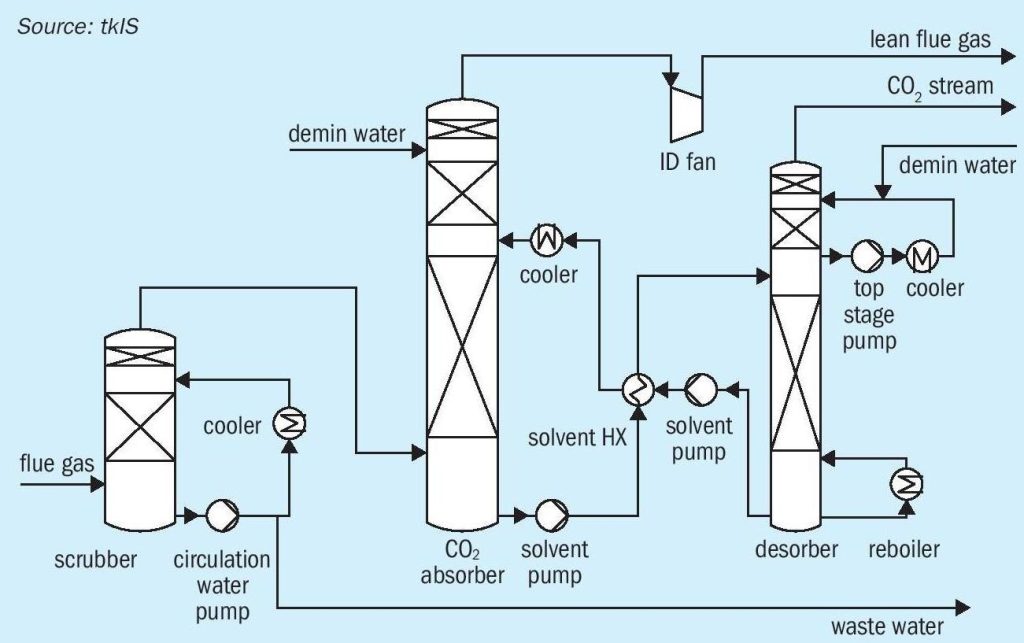
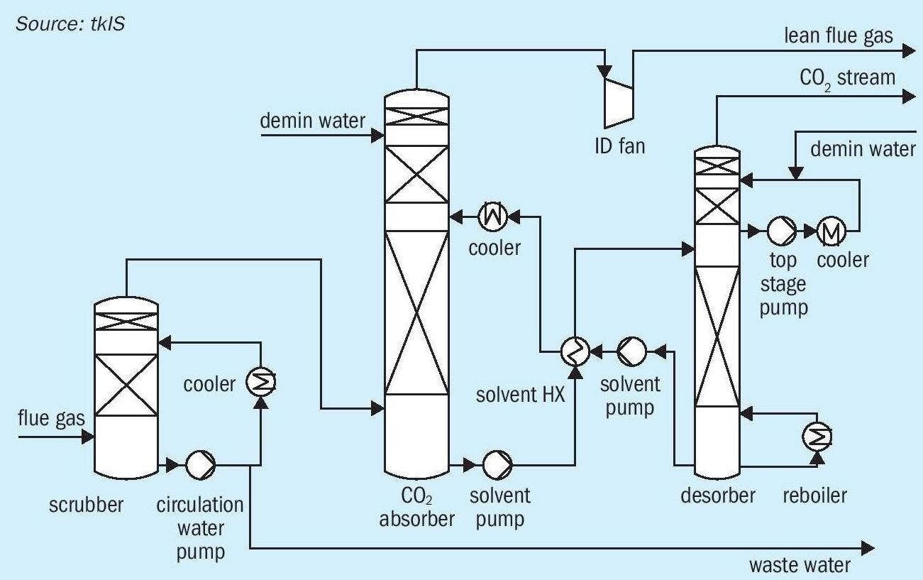
For green methanol production, hydrogen from AWE is used as a raw material, but carbon dioxide, recovered e.g. from flue gas, is also required. CO 2 -rich flue gases are emitted from almost every industry sector, e.g. cement production, power plants, and steel production. For all kinds of industry, it becomes more and more important to improve process efficiency and decrease emissions of greenhouse gases. Some countries have already raised carbon taxes which can have a negative impact on the economics of conventional industrial processes. tkIS, a sustainable, technology-oriented company, is part of thyssenkrupp AG (tk), one of the leading steel-producers in the world. To decrease CO 2 emiss ions at the tk steel plant in Duisburg, tkIS established a pilot plant for CO 2 recovery from flue gas by means of amine gas treating (see Fig. 1).
Flue gas is sent to a pre-scrubber where water soluble components (sulphurous) are removed by washing with small amounts of water. Subsequently desulphurised flue gas is sent to a CO 2 absorber where CO 2 is absorbed by solvent. Lean flue gas is then sent to battery limits and loaded solvent is sent to the desorber, where CO 2 is separated and aqueous amine solution is regenerated. The solvent is returned to the absorber column, and the purified CO 2 stream can be sent to downstream processes such as methanol synthesis. With this amine-based CO 2 removal technology 90% of CO 2 can be recovered from flue gas.
Methanol as energy storage and carrier
As already mentioned, one of the main challenges of using renewable energy is the fluctuation of supply, another is the often large distances between the locations of production and use of renewable energy, which causes considerable transmission losses.
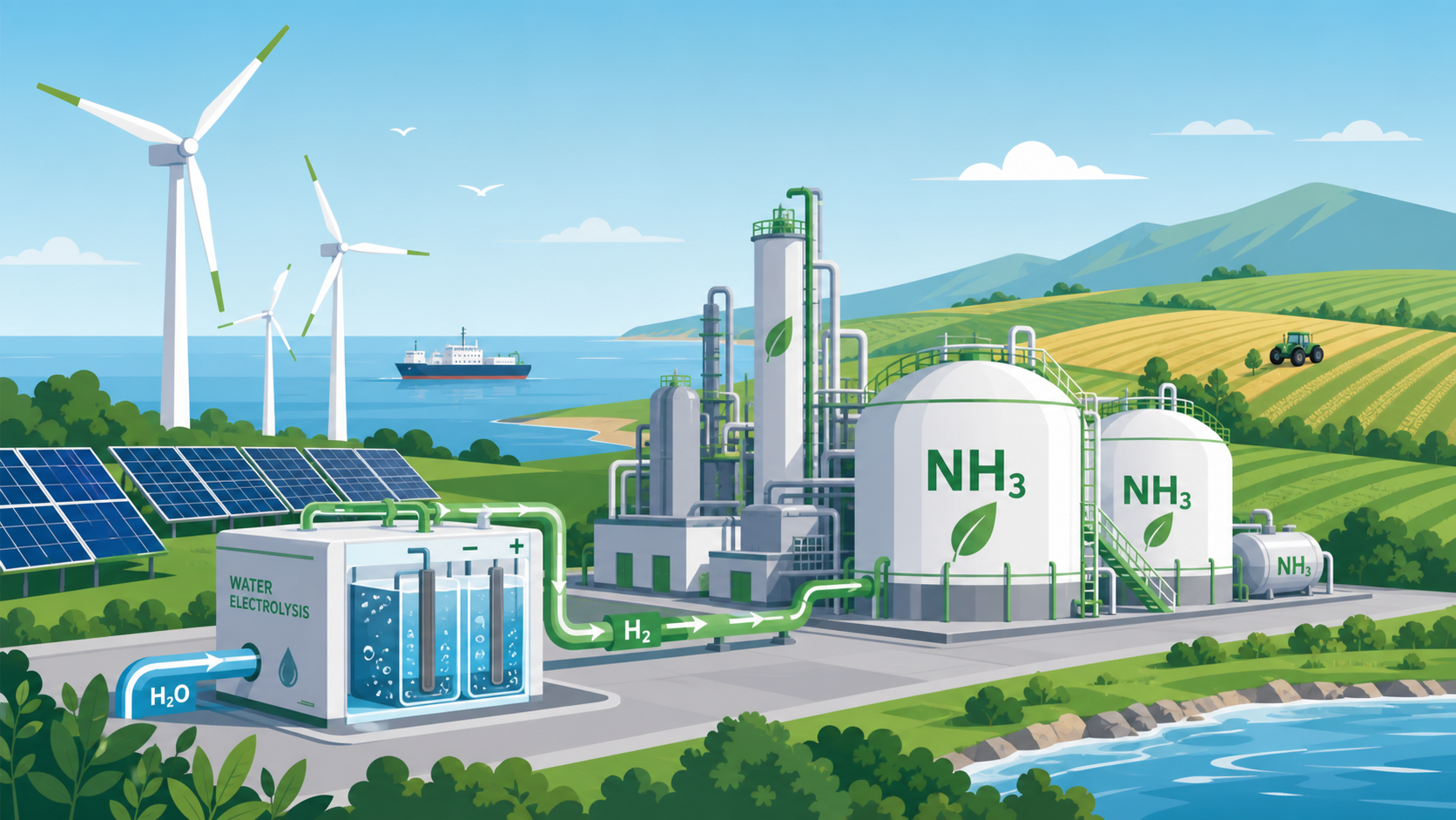
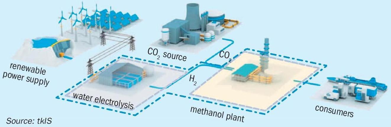
Energy storage and carrier solutions can be useful to overcome these challenges. SNG, ammonia, redox flow batteries and methanol have been considered for potential energy storage and carrier solutions in the energy sector. Methanol in particular is highly suitable as a high-density energy carrier, as it provides the opportunity to store green energy in terms of green fuel. The basic requirement for green methanol production is renewably-produced hydrogen, but CO 2 is also required (see Fig. 2). Carbon capture and utilisation may be a promising solution for a significant reduction of greenhouse gas emissions. Furthermore, the economics of renewable methanol production can be improved via carbon emission trading. As a result, sector coupling should be taken into account for sustainable plant concepts.
Decentralised production of e-methanol in direct proximity to power plants or CO 2 sources is an interesting and promising example of sector coupling. By blending green methanol to the gasoline pool, available infrastructure and logistics can be used. E-methanol, which can be produced self-sufficiently, independent from oil or fuel imports, can be used to substitute fossil gasoline.
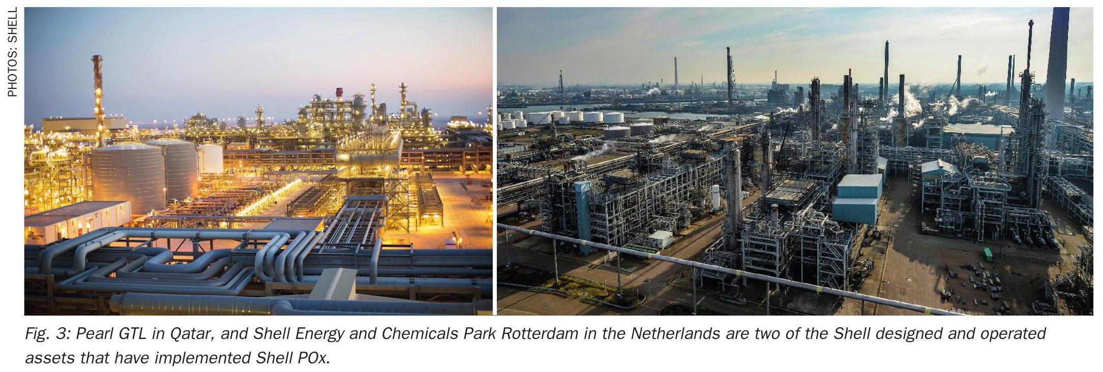
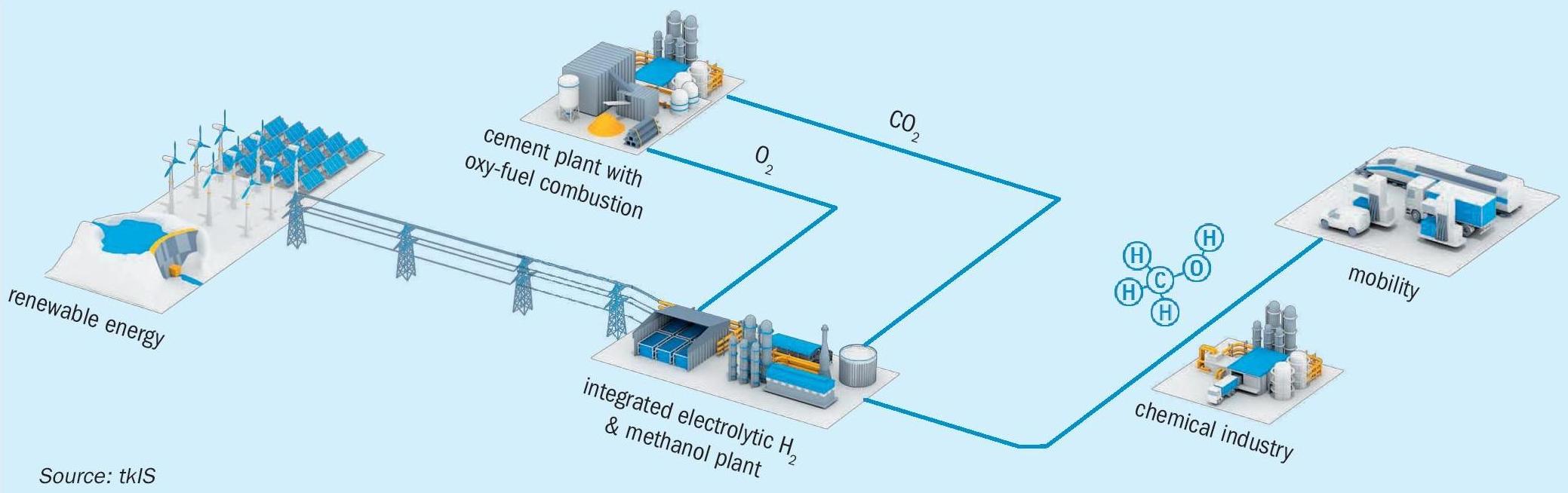
As the cement industry is one of the largest CO 2 emitters, sector coupling of the cement industry with renewable energy production and the mobile/chemical sector is another promising option (see Fig. 3). Oxygen from electrolysis can be used in the cement plant for oxy-fuel combustion. By using oxy-fuel combustion, a high CO 2 content in the flue gas can be reached. As a result, efficient capture and use of CO 2 for production of renewable methanol can be realised.
Renewable methanol production technology
Renewable methanol plants are very similar to conventional world-scale methanol plants. Both processes can be divided into three steps; syngas production, methanol synthesis and methanol distillation. They differ in the way they produce syngas. In conventional methanol plants, syngas for methanol synthesis is produced via steam reforming, partial oxidation or autothermal reforming of natural gas, or by gasification of solid or liquid fossil fuels.
In renewable methanol plants, hydrogen is produced via water electrolysis. The carbon dioxide required for the methanol synthesis can come from a flue gas recovery unit or a renewable source such as a biogas or bioethanol plant. Both gases are mixed and sent to the methanol synthesis section. Crude methanol is purified in the methanol distillation section to achieve the desired methanol specification.
The concept for methanol synthesis is quite standard. For methanol synthesis from CO 2 commercially available Cu-based catalysts can be used. Reactor temperatures of between 210°C and 270°C have to be realised with this catalyst type. A minimum temperature is necessary to start the reaction and a maximum temperature should not be exceeded to prevent catalyst deactivation and reduce by-product formation. As CO 2 – based methanol synthesis is less exothermic compared to CO-based methanol synthesis, a comparatively high cooling temperature is chosen. Formation of methanol from CO 2 is also favoured by high pressure, so a reaction pressure in the range of 60 to 80 bar is used.
In the methanol reactor the following main reactions take place:
- CO + 2H 2 CH 3 OH
- CO 2 + 3H 2 CH 3 OH + H 2 O
- CO 2 + H 2 CO + H 2 O
Less catalyst is required for conventional CO-based methanol synthesis compared to methanol synthesis from CO 2 , but a higher number of hot spots in the reactor can lead to higher by-product formation during methanol synthesis from CO.
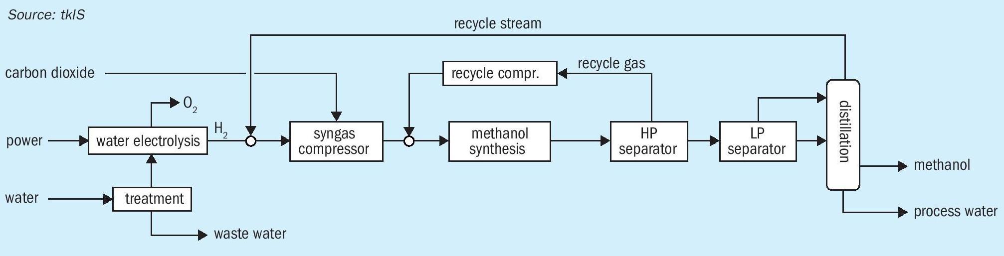
To achieve near isothermal conditions during methanol synthesis, a water-cooled tube bundle reactor is used where process gas on the tube side is cooled by evaporating water on the shell side of the reactor. After partial evaporation, a steam water mixture leaves the shell side at the top. This type of reactor is already in operation in conventional methanol plants. The process concept for renewable methanol syntheses is shown in Fig. 4.
Fresh water is sent to the water treatment unit to meet the specification for AWE. Subsequently, demineralised water is electrolysed to hydrogen and oxygen.
Depending on the battery limit conditions of CO 2 , gas supply of hydrogen and CO 2 can be coupled to improve process efficiency. If CO 2 is supplied in liquid state, the cooling energy of CO 2 evaporation will be used for hydrogen cooling. Normally CO 2 is supplied at lower than synthesis pressure, so a common compression of carbon dioxide and hydrogen is realised. Carbon dioxide, recovered from a CO 2 -emitting process is added in stoichiometric composition to hydrogen.
Hydrogen is mixed with the recycle stream from the column overhead and sent to the first compressor stage. Depending on the battery limit conditions, carbon dioxide is added to one of the following compressor stages. Compressed feed gas is mixed with recompressed recycle gas from the high pressure separator and is fed into the methanol synthesis reactor. In the high pressure separator unreacted gas is separated from crude methanol. Crude methanol is sent to the low pressure separator and subsequently to the methanol distillation column. In the distillation column dissolved carbon dioxide and light by-products are separated at the column head, heavy by-products and water accumulate at the column bottom, and pure methanol is withdrawn as a sidestream. Process water is routed to battery limits; fuel methanol can be further used for gasoline blending.
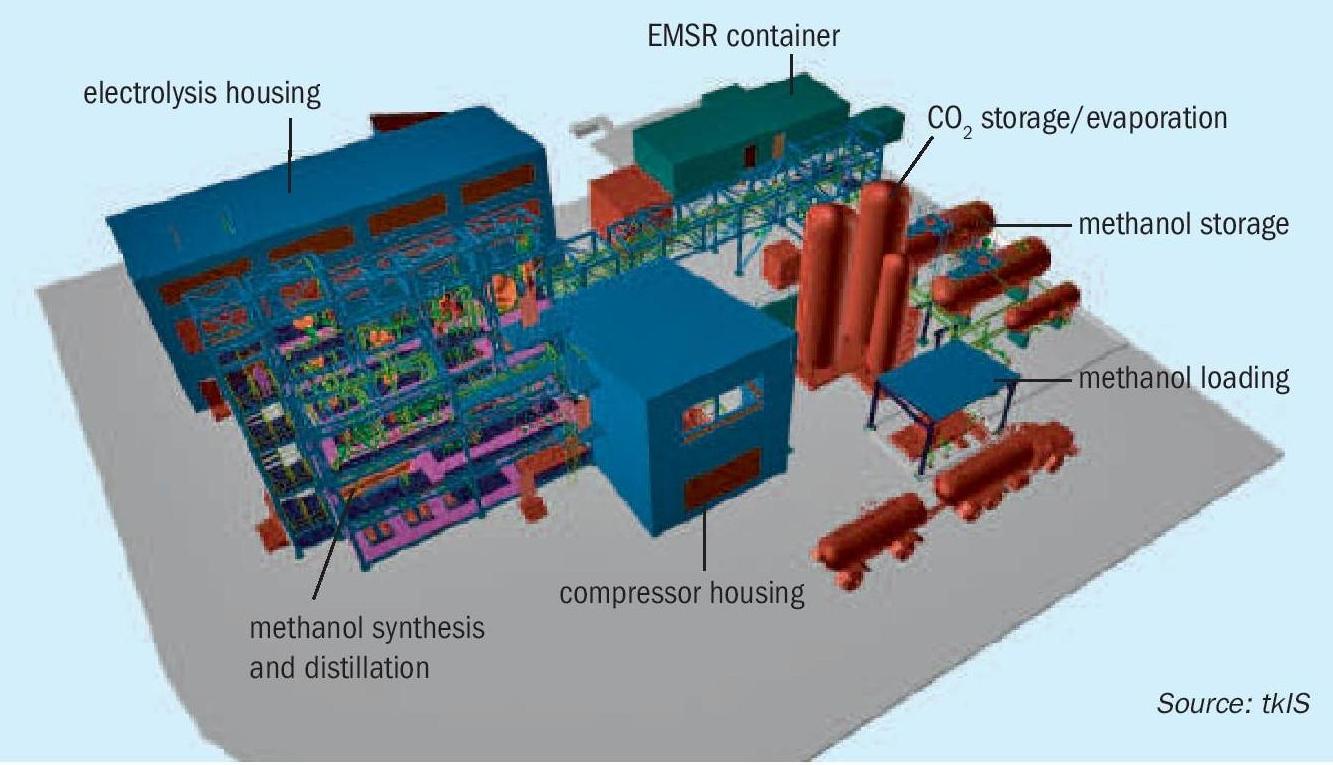
The UHDE green methanol process can be easily adjusted to local and specific project requirements. The plant can either be provided as a so-called stick build lay out, taking advantage of regions with low construction prices, or in modules, prefabricated and precommissioned in workshops for quicker installation. Due to tkIS’ modularisation expertise, a wide range of plant capacities can be realised in modularised design. A 3D model of tkIS’ advanced modularised renewable methanol plant including water electrolysis is shown in Fig. 5.