Nitrogen+Syngas 364 Mar-Apr 2020

31 March 2020
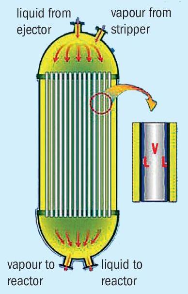
Problem No. 59: Troubleshooting the condensation capacity of a falling film HPCC
The falling film high pressure carbamate condenser (HPCC) was the first type of high pressure carbamate condenser applied in urea stripping plants. Did you know that the first Snamprogetti stripping plants also had falling film carbamate condensers? In 1978 Mr Umberto Zardi, later founder of Casale, invented the horizontal kettle type condenser for Snamprogetti urea plants.
The process performance (read condensation capacity) of falling film high pressure carbamate condensers in a urea synthesis section depends on many factors, amongst others synthesis pressure, N/C and H/C ratios, inert content on the process side and steam side, circulation rate on the steam side, etc. Calculations on the process side are limited and not much actual operating data is available.
This makes it difficult to troubleshoot a falling film high pressure carbamate condenser that lacks condensation capacity. And that is exactly the topic of this round table discussion.
Muhammad Farooq of SAFCO in Saudi Arabia starts the round table discussion which refers to an issue he faced in his earlier job: We have two carbamate condensers in parallel in our urea synthesis section. We are experiencing the problem of a low heat-transfer coefficient despite conducting chemical cleaning. Due to low condensation capacity we have synthesis section pressure hikes in the loop.
Please note that if we decrease the steam flow/pressure to the urea stripper, it increases the residual ammonia at the outlet of the stripper. Increasing steam pressure also results in a decrease in condensation capacity at the HPCC as the stripper steam condensate flows on the shell side.
We control the synthesis pressure at around 146 kg/cm2 as per design of our licensor. What measures are available to overcome this problem?
Mark Brouwer of UreaKnowHow.com, the Netherlands asks for some clarifications:
- Are we talking about the TEC ACES process?
- Do you have this problem in both HPCCs?
- Are all tubes available or are some tubes plugged?
- Is there any chance of inert build up on the steam side?
Muhammad replies:
- Yes our plant is basically TEC ACES but after carrying out a revamp in 2010, it was changed to the Stamicarbon process.
- The problem exists with both HPCCs. We have diverted the maximum liquid ammonia to increase the conldensation capacity at the inlets of both HPCCs.
- There are no plugged tubes in the HPCCs, both are in very good condition after 15 years of operation.
- How do we check the inert content on the steam/condensate side? Tube side inerts are in range as we analyse gases at the washing column exit.
Mark comes back with a suggestion and some more questions: You could open the inert vent on the steam side and see if the situation improves. But as both HPCCs suffer the problem and one HPCC has steam on the shell side and the other carbamate (am I right?), the problem seems to be on the tube side. Did it change suddenly or slowly and since when? Has there been any change in process conditions?
Muhammad replies: The shell side of both HPCCs contain steam condensate. The problem of synthesis pressure greater than 146kg/cm2 is observed when the plant load is increased by more than 90%. The carbamate condenser bottom temperatures are below design. The change is consistent. The major change in the process is that with TEC we were operating at a N/C ratio = 4, while now it is lower.
Mark asks further: Could inert pressure be higher on the process side? Are several synthesis temperatures on the lower side?
Muhammad Kashif Naseem of SAFCO in Saudi also has some questions: Please share your N/C ratio, generated steam pressure and top/bottom temperature.
Muhammad replies: You will find some of the answers below: The steam pressure at low load operation is already on the low side (3.8 kg/cm2 against design 3.5 at 100% load), N/C =3.1, reactor top/bottom =185.2/172.8°C against design =183.3/173.5°C. The inert level is under control and we don’t believe it is the inerts that are increasing the system pressure.
Easa Norozipour of Khorasan Petrochemical Company in Iran asks further: Did you change the stripper or is the stripper still as per TEC license. I think if you didn’t change the stripper as per Stamicarbon license and the N/C ratio is decreased, the main cause must be the new N/C ratio.
A second cause may be a mechanical problem like damage to the distributor in the top of the HPCC.
Muhammad Kashif Naseem shares his experiences: The data provided is very brief but it seems that the condensation rate across the HPCC is too low and the carbamate solution has a high density.
Muhammad responds to comments: We did change the stripper as per Stamicarbon recommendations and our N/C ratio is as per the licensor. We checked both HPCCs during our annual turnaround and both were found to be normal. What is your viewpoint as regards the heat load generated at the stripper and requirements to be absorbed by the HPCC?
A far as operation is concerned, it is ok, however for better optimisation of process parameters we need countermeasures to overcome the condensation capacity and want to benefit from revamping expertise.
Majid Mohammadian of OCI Nitrogen in The Netherlands joins the discussion: In typical HPCC Stamicarbon urea plants the synthesis pressure transmitter is in the HP scrubber overflow line, in a pool condenser type it is located in the ammonia inlet to the pool condenser and in your plant it is in ammonia inlet to the reactor, so the normal synthesis pressure in your case should be higher than the original Stamicarbon plants let say something around 148 to 150 kg/cm2 . I think it might be possible to increase the plant capacity with normal synthesis pressure of about 148 to 150 kg/cm2 .
Mark provides a further suggestion: Did you compare the overall heat transfer coefficient (U) before and after the revamp? A reasonably accurate (but certainly good for comparison purposes) value of U can be calculated via:
Q = U x A x (T process – T steam )
T steam is the saturation temperature of the steam at the operating steam pressure and Q = Flow LP steam x dH evap
Farzan Bashir of Fauji Fertilizer Company in Pakistan shares his experience: Please check that your steam header pressure is in range, because in case of higher steam header pressure there will be less condensation in the HPCC.
This series of discussions is compiled from a selection of round table topics discussed on the UreaKnowHow.com website. UreaKnowHow.com promotes the exchange of technical information to improve the performance and safety of urea plants. A wide range of round table discussions take place in the field of process design, operations, mechanical issues, maintenance, inspection, safety, environmental concerns, and product quality for urea, ammonia, nitric acid and other fertilizers.