Sulphur 390 Sept-Oct 2020
30 September 2020
One size does not fit all
MERCAPTAN REMOVAL
One size does not fit all
K. Hanlon Kinsberg and J. Lewis of Comprimo review the main approaches for mercaptan removal in gas processing plants, based on past project experience and generally accepted industry practice.
Mercaptans are a common contaminant in the feed to gas processing plants, along with H2 S, CO2 , carbonyl sulphide, mercury and water. Just as gas plants themselves come in a wide variety of process configurations driven by differing gas export specifications dependent on local market conditions, so too can there be an array of contaminant removal methodologies1 .
The best mercaptan removal process for a given site with defined feed conditions will depend on many factors. First and foremost, it is recommended that this evaluation is done holistically, considering the impacts on the overall gas plant configuration. Mercaptan removal can govern the entire gas-side configuration of a processing train2 , and it is a significant example of the interdependence between hydrocarbon processing and impurities removal. Depending upon the functional requirements of the gas plant, the design engineer needs to ask where the best place is to remove the mercaptans.
There are several gas processing options available for mercaptan removal, with the most common including solvents, adsorption with molecular sieves and NGL recovery with liquids treating. Each process has its advantages and disadvantages depending on the level of mercaptan removal required and how the removal integrates with the overall gas conditioning required.
Importance of accurate fluid analysis
The first step in determining the most suitable mercaptan removal approach for a new plant design is ensuring a rigorous reservoir fluid analysis is available. Understanding both the level of mercaptan contamination as well as the species distribution is critical when evaluating technology selection for the gas processing plant. Too often, projects make fundamental assumptions on the design basis if field data is either limited or incomplete, without appreciating the consequences of those assumptions.
The feed composition details are pivotal and can have tremendous ramifications on the process configuration and ultimately the overall plant performance. One design approach is to be “conservative” in the assumptions, and then proceed with technology selection from that baseline. But unfortunately, that conservativism could inflate the overall project cost due to over-design or it could misdirect the technology selection process. It is acknowledged that reservoir fluid characteristics can change over the life of a field, which sets the expected operating boundary for the processing plant, but there still needs to be solid analysis data at the technology selection phase for the best design foundation.
For example, solvent selection for acid gas removal depends upon the concentrations and species of contaminants expected. Such a fundamental design decision is increasingly difficult to alter as the project progresses through the engineering phases and into construction and startup, if new field data reveals significant changes to the original design basis.
Case study
Impact of uncertainty of mercaptan levels3
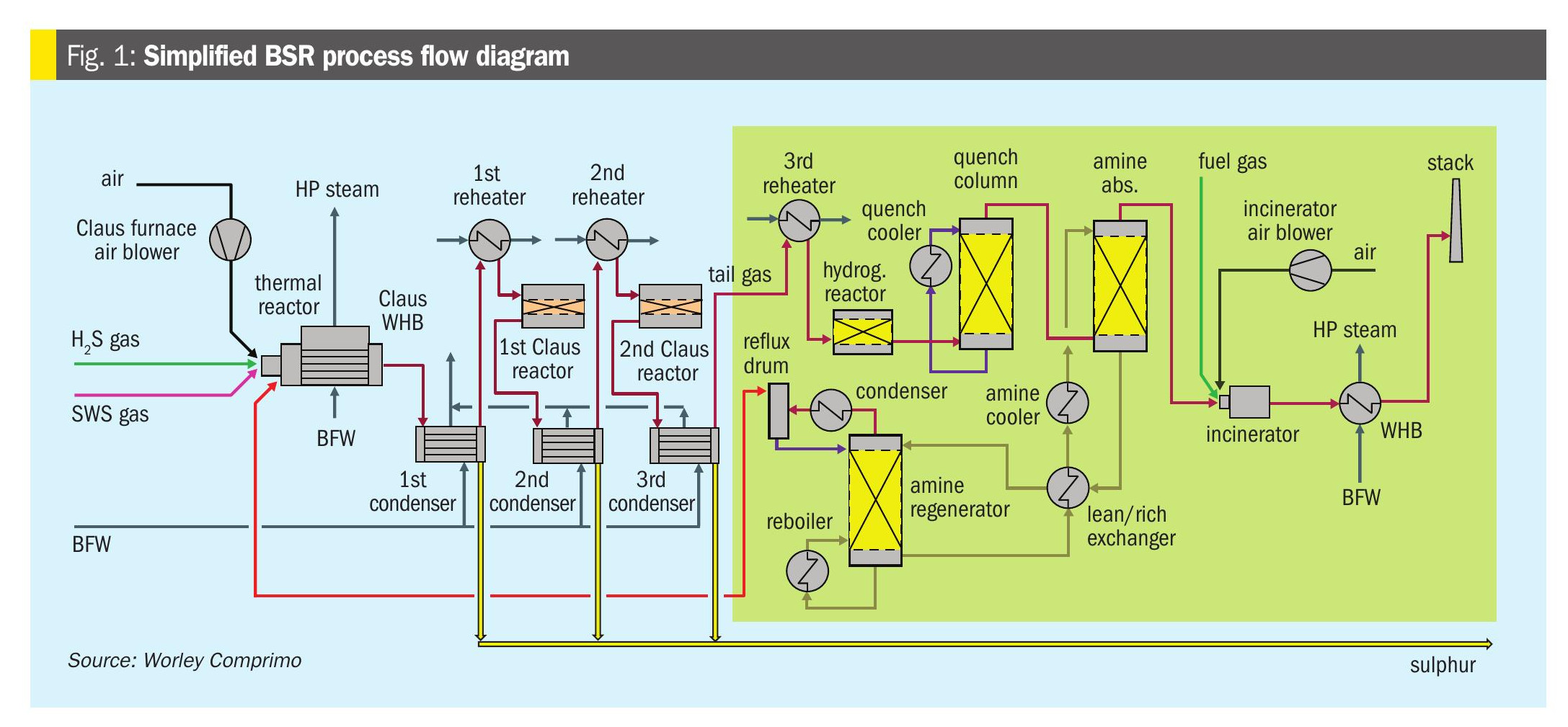
In this study a hybrid solvent, containing amine for H2 S removal and concomitant CO2 reduction, and a physical component for removal of organic sulphur species, primarily mercaptans, was used in the gas sweetening unit to treat a natural gas stream. The use of a physical component resulted in some absorption of hydrocarbon components, which were released in the high-pressure flash drum and the solvent regeneration facilities and subsequently lost, thus contributing to the acid gas stream routed to the SRU.
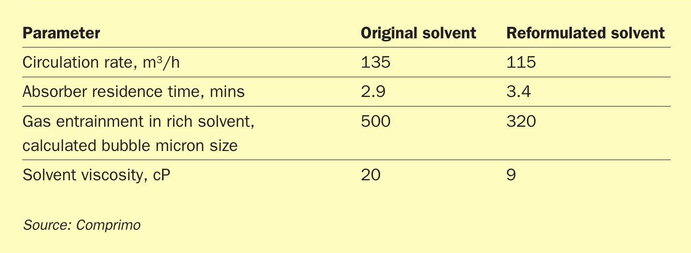
During plant operation the concentration of mercaptans in the feed gas was much lower than that used in the design basis for the facility resulting in a suboptimal design. Opportunity was seen to reformulate the solvent to address this by reducing the physical component concentration to reduce the physical absorption of hydrocarbon components, leaving them in the treated gas stream, thereby reducing the flash gas rates and improving the quality of the acid gas stream to the SRU. Other advantages achieved were higher CO2 slip in the H2 S absorber, lower emissions, reduced power consumption, reduced entrainment of gas bubbles in the rich solution and improved performance of the flash drums.
In order to prove that the installed plant could operate with the reformulated solvent, checks were made on each component. Table 1 contains a summary of solved related parameter changes. There was essentially no change in the reboiler and lean/rich solvent exchanger duties.
This example serves to illustrate that the removal of contaminants in gas streams should not be considered independently from the requirement to process the hydrocarbon components to meet the product specifications. The degree of interdependence for an optimum overall processing scheme will differ for each application and must be carefully considered during the design phase.
Mercaptan removal options
The gas processing plant complexity increases when reviewing how best to remove mercaptans; three main approaches can be used1 :
- in the AGRU with a hybrid solvent (i.e., chemical and physical solvent combined);
- from NGL condensed in the NGL recovery unit, using a caustic-based process;
- combined with dehydration in a molecular sieve process, with additional treatment on the molecular sieve regeneration gas.
Some less commonly applied processes include gas caustic treating, scavengers/ inhibitors and membranes, but there can be instances where they are best suited to the plant conditions.
Solvent processes
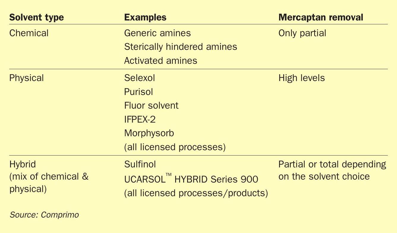
When reviewing the processes for mercaptan removal, determine if the mercaptans can be removed along with the acid gas species, primarily H2 S and CO2 . Several solvent technologies are available for this purpose with varying degrees of mercaptan removal. See Table 2 for a comparison of common solvent types available.
Natural gas liquids recovery and liquids treating
There can be situations where it is considered more efficient to remove mercaptans from the natural gas liquids (NGL) rather than the inlet gas streams. It can be expected that the NGL volumes will be significantly lower than the total gas throughput of the plant, and the mercaptan concentrations higher in the liquid stream. These higher concentrations make the mercaptan removal easier than at dilute levels in the total gas. Once in the liquid phase, there are various options to consider for the mercaptan treating. For an in-depth review of technology selection for NGL treatment refer to a 2017 paper from the Laurance Reid Gas Conditioning Conference (LRGCC)6 . A recent development is the Exion LT system for mercaptan removal from hydrocarbon condensates and NGL streams. The patented technology utilises a non-regenerable chemical additive within the process to capture H2 S and mercaptans. Initial pilot plant testing results were presented at LRGCC in 20167 .
Adsorption processes
If the required level of mercaptan removal is not possible or feasible with solvents, another common approach is to consider fixed-bed adsorption. Options include:
Regenerable processes with molecular sieves/silica gel
- Gas composition dictates the quantity of adsorbent required and therefore the subsequent vessel size.
- The adsorption process offer a two-fold application, as are also used for gas dehydration.
- If molecular sieves are already required for gas dehydration, it would be only an incremental cost of the extra bed depth for mercaptan removal. In some instances, the quantity of molecular sieve needed for mercaptan removal could be higher than that for dehydration, depending on the relative concentrations.
- Regenerable adsorption is a well-established technology.
- The main challenge is how to manage the regeneration gas. From experience it has been found that the cost of dedicated regeneration gas treatment with a physical solvent can be equivalent to the cost of the molecular sieves themselves. In the past, incineration of the regeneration gas was a reasonable option. That is not generally feasible in the current era of stricter emissions controls where total sulphur discharge is measured. Extra focus is required to find the most appropriate treatment option for the regeneration gas depending on overall gas plant configuration.
- Adsorption is favoured by high partial pressure and lower temperatures.
Non-regenerable solid adsorption
- Chemical adsorbent.
- Used for only trace amounts of mercaptans.
- Similarly to the regenerable adsorbent the volume of adsorbent required is proportional to the mercaptan content.
- Two main disadvantages for non-regenerable adsorbents: whether they can meet specification and whether they can handle the capacity of mercaptans.
Gas caustic treatment
Suitability of this process depends on the CO2 content of the inlet gas. If the CO2 is too high, it reacts irreversibly with the caustic catalyst. To make this process viable the upstream amine unit would have to be adapted to remove CO2 in the gas for mercaptan removal to very low levels.
Caustic is more typically used for treating hydrocarbon liquids. It’s important to note that H2 S and CO2 will consume caustic, so this process should be used downstream of the bulk acid gas removal process.
Within the context of caustic treatment, of special note are the findings presented at LRGCC in 2014 regarding the chemistry and predictability of mercaptan removal from gas streams with amines and caustic8 . The referenced paper highlights three considerations when designing a mercaptan removal unit which can meet a treated gas performance guarantee; selecting the proper processing strategy, understanding the chemistry and effect on phase equilibrium, and using the right simulation tool in the process design. Simulation tools have greatly advanced in recent years in their ability to better estimate mercaptan removal performance, when given the most accurate feed conditions available.
Scavengers/inhibitors
Scavengers/inhibitors are used for polishing, with low levels of H2 S and mercaptans to be removed. There is limited data available regarding mercaptans performance. CO2 can consume the chemical in some formulations.
Membranes
Membranes have a well-established performance history for bulk CO2 removal and are not usually used for other acid gases. There have been recent developments in the use of membranes for mercaptan removal. Chevron has patented a pair of systems where the mercaptan-selective membranes are installed on the cooled regeneration gas stream from the molecular sieves for dehydration, and upstream of the fractionation unit9 . This methodology of removing the mercaptans from the gas stream is designed to meet the LPG sales specification while avoiding caustic treatment.
Another development is rubbery membranes which have been recently commercialised and demonstrate mercaptan removal not previously possible with the traditional glassy membranes common in CO2 removal10 .
Conclusions
- Accurate reservoir analysis is needed to avoid over-design or errors in technology choice.
- Use a holistic approach in technology selection for mercaptan removal in concert with fixing the overall plant configuration.
- Sales gas specification and further downstream processing have impacts on mercaptan removal.
References