Fertilizer International 499 Nov-Dec 2020

30 November 2020
Challenging larger granulation capacities
GRANULATION TECHNOLOGY
Challenging larger granulation capacities
As urea plants grow in capacity, so does the need for finishing technologies with higher capacities. Barbara Cucchiella, senior process engineer at Stamicarbon, describes how her team has risen to the challenge of the global trend for larger granulation plants.
Stamicarbon, the licensing and innovation centre of Maire Tecnimont Group, has always been at the forefront of developments and innovations in urea granulation. This has resulted in the company significantly increasing its global market share for granulation licensing over the last five years.
Urea granulation plants are typically constructed in countries with access to abundant low-cost feedstocks. Because of their competitive production economics, such plants are able to manufacture low-cost, high-margin granulated urea products for the export market. While there are several finishing options to choose from, fluid bed granulation still remains the best choice for urea that is destined for export and/or transported over large distances – due to the better strength, handling and shipping behaviour of the resulting granules.
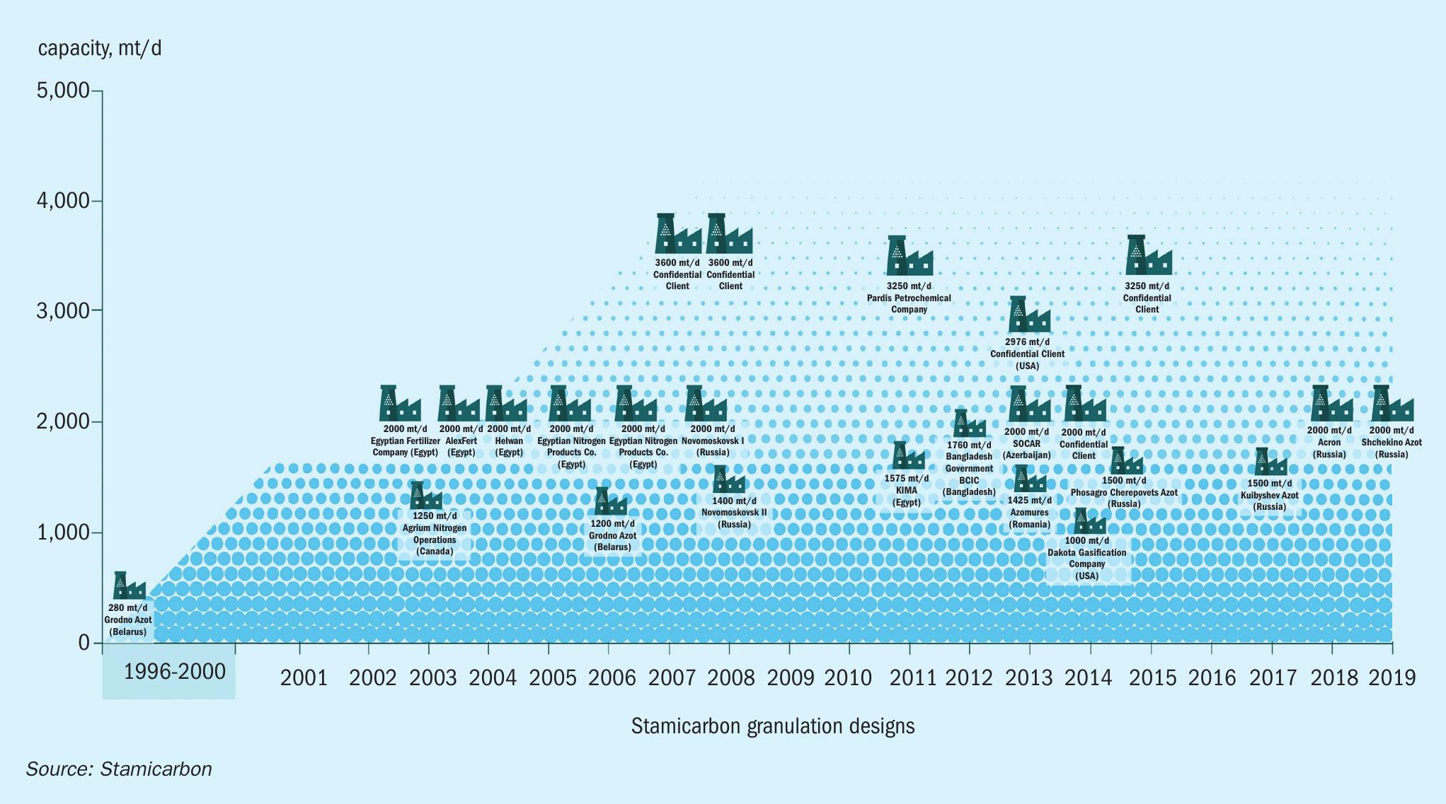
Over the last decade, Stamicarbon has seen a rapid rise in the design of plants with higher maximum capacities (Figure 1).
At the moment, annual growth in market demand for urea is running at about 1.5 percent, equivalent to the construction of 2-3 new large-scale granulation plants every year.
Optimised granulation plant design
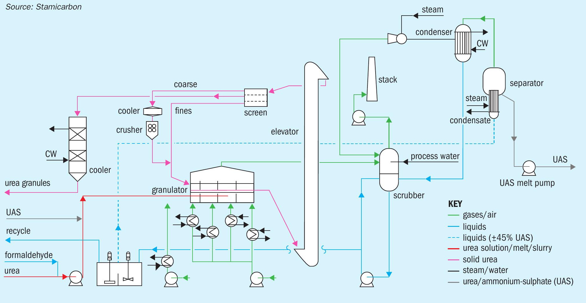
Stamicarbon introduced its optimised LAUNCH FINISH ™ granulation design in 2008 (Figure 2). This optimised design incorporates a minimal number of equipment items and features CAPEX and OPEX cost reductions, while keeping to its original performance parameters and high on-stream times.
The new design delivers a 20 percent cost saving in power consumption – mainly achieved by the omission of three fans. Increasing the length of the cooling zone, compared to the original granulator, also allowed the fluid-bed granulator cooler to be omitted. This enabled the fan and all the pumps associated with the granulator cooler scrubber to be discarded too. Additionally, the fluid-bed product cooler was replaced by a solids flow cooler. The granules produced are now cooled down in the last compartment of the granulator. In the new design, only one separate fluid bed cooler is needed – a crusher feed cooler (fluidised bed cooler) – for cooling down the coarse product.
Process description
Liquid melt is still fed to the granulator as per the original design. However, the last compartment of the granulator, where the end product is now cooled down to a lower temperature, does differ from the previous design.
On exiting the granulator, having passed the lump screen, the product is lifted directly to the screening equipment via a bucket elevator. All the solid product then flows through the main screens under gravity.
The coarse oversize generated is fed to the crusher, after firstly cooling to a temperature of 70°C. The undersize from the main screens and the crushed product are combined and recycled back to the granulator as so-called seeds.
Meanwhile, on-specification product emerging at the outlet of the main screens is cooled to storage temperature in a solid flow cooler. This makes use of cooling water instead of cooling air. Dust-loaded air is collected from the granulator and all the de-dusting points and fed to a single granulator scrubber.
Finally, to reduce the amount of fluidisation cooling air, a water injection system is provided at the discharge of the fluidisation air fan. This is only operated on exceptionally hot days to increase the relative humidity while at the same time reducing the total air consumption.
The lower number of equipment items significantly reduces the overall capital cost of the plant and its installation footprint. Additional cost savings in transportation (shipping), insurance and construction also contribute to the CAPEX cost reduction. Fewer equipment items, by cutting maintenance costs, also deliver an OPEX saving.
Reference plants
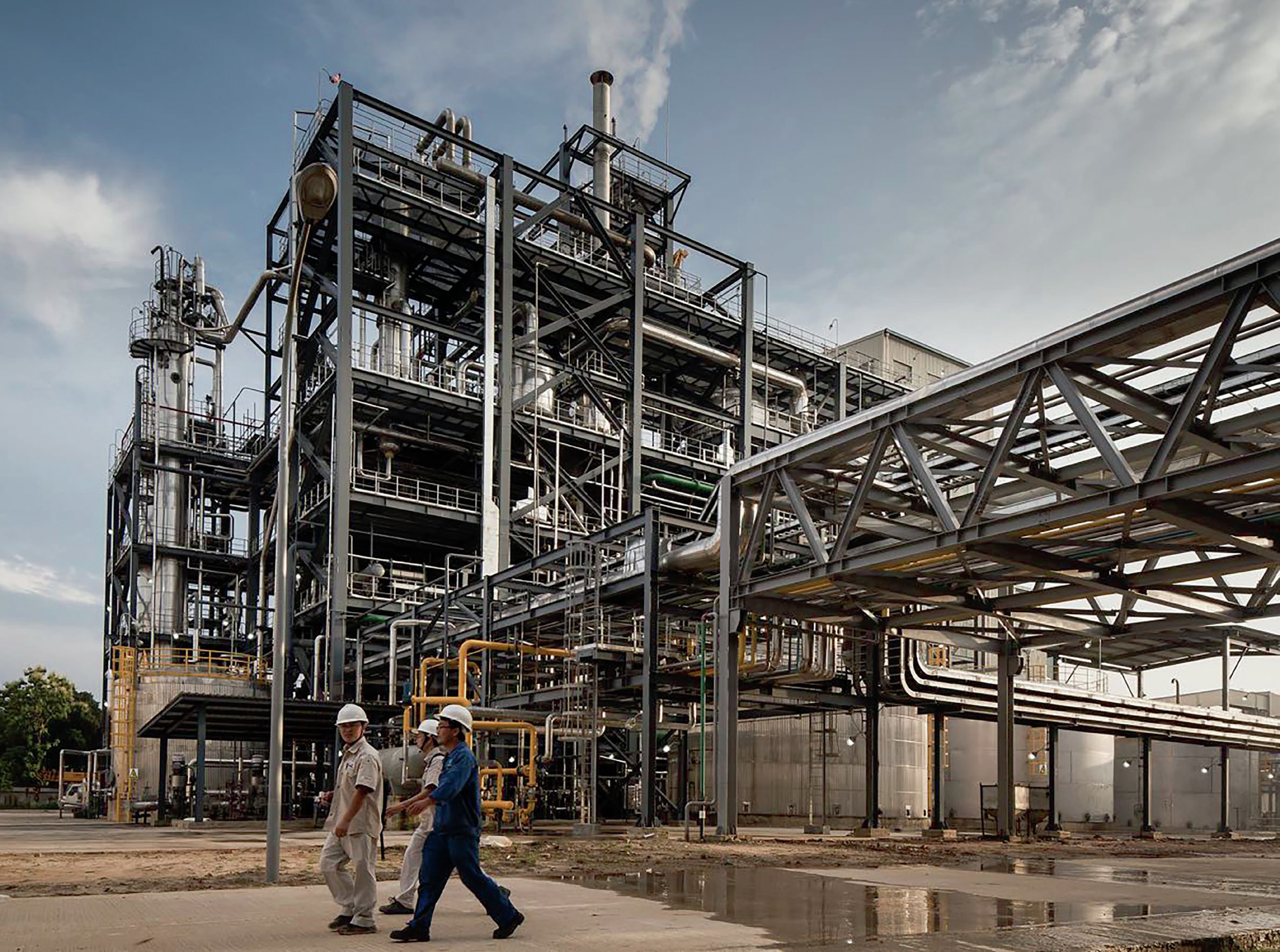
The first granulation plant based on the new LAUNCH FINISH™ optimised design was the 1,760 t/d capacity plant commissioned for Shahjalal in Bangladesh in 2015 (see main photo). The plant started up very easily and still operates extremely reliably and smoothly with minimal operator attention required. The power consumption met expectations, being 20 percent lower than the conventional design, and plant maintenance costs have also been significantly reduced. Product specification exceeds standard commercial quality requirements for urea, even at formaldehyde levels lower than 0.30 percent in very humid ambient conditions.
“Investigations into scaling-up granulation plant design capacity to more than 5,000 t/d have concluded that there are no actual showstoppers.”
Further experience of the optimised design was gained from the construction and commissioning of the 13 plants that followed subsequently.
Although granulation plants with higher capacities are currently on the drawing board at the design stage, a plant with a nameplate capacity of 2,676 t/d is the highest capacity optimised design plant currently operating. This granulation plant, originally contracted in 2012 and subsequently started up in 2018, finishes urea produced by a Stamicarbon-designed pool reactor plant. As well as overall plant design, Stamicarbon also provided all the necessary equipment, including the granulator and the MicroMist™ venturi scrubber. The plant is currently operating above nameplate capacity although it can also operate at a turndown capacity of around half this output level.
Scaling-up to really large capacities
Stamicarbon has seen a rapid increase in the design capacity of urea plants over the last 10 years. Nowadays, urea granulation plants with a capacity close to or higher than 3,000 t/d are in operation. But the biggest challenge is scaling-up beyond this level to even larger capacities.
Recent experience from starting-up a 3,250 t/d granulation plant with Stamicarbon’s original granulation design have been highly positive, with client expectations being met. Such large capacity plants can easily meet their performance guarantees, despite having different product requirements, different ambient conditions and different configurations.
Moreover, investigations into the possibility of scaling-up granulation plant design capacity to more than 5,000 t/d have concluded that there are no actual showstoppers – provided that extra measures to anticipate the risks of scaling-up are implemented. Furthermore, it’s estimated that a single train 5,000 t/d plant requires around 30 percent less CAPEX (total investment) versus a plant design based on two trains of 2,500 t/d each. Consequently, Stamicarbon is now fully prepared and ready to offer and build its first single train 5,000 t/d LAUNCH FINISH™ granulation design.