Nitrogen+Syngas 369 Jan-Feb 2021
31 January 2021
Reducing CO2 emissions with AdWinMethanol CC®
BLUE METHANOL
Reducing CO2 emissions with AdWinMethanol CC®
In a carbon-constrained world, carbon capture and utilisation or storage (CCUS) installed on a methanol plant is a necessary and feasible solution. The new, patented AdWinMethanol CC® technology, jointly developed by thyssenkrupp Industrial Solutions AG and GasConTec GmbH, integrates carbon capture into large-scale, natural gas-fuelled methanol production to yield a drastically reduced carbon footprint. U. Koss and W. Balthasar of GasConTec and J. Wagner of thyssenkrupp Industrial Solutions discuss how it removes CO2 emissions in an efficient, cost effective, and environmentally friendly manner, taking advantage of the design features of AdWinMethanol®.
Global demand for methanol is growing continuously, with market volume and production capacities predicted to rise by around 4.3% p.a. over the next ten years 1 . Without mitigation measures in place, this will inevitably lead to a corresponding growth in associated CO 2 emissions. The CO2 emitted by the world’s methanol plants is already significant. In 2018 methanol production contributed 24% (211 million tonnes out of 875 million tonnes 2 ) of the total CO2 emissions from the production of primary chemicals, a contribution that is trending upwards. The reduction of emissions from methanol plants will be of paramount importance on any roadmap towards a carbon-neutral chemical and petrochemical sector which currently accounts for approximately 20% of total industrial CO2 emissions 2,3 . In view of the lively activity of the respective regulatory authorities, methanol producers can expect the imposition of emissions regulation which will, on one side, penalise high CO2 emissions and on the other side, yield a competitive edge for plants with a small carbon footprint. This will drive the need for new and innovative technologies that can deliver affordable methanol with a low or zero CO2 emissions footprint.
To achieve this goal, there are several technological pathways 4 : “Green” methanol can be produced from “green” hydrogen, produced from renewable power, and CO 2 from biogenic sources or direct air capture (DAC) by means of powerto-methanol (PtM) technology. Sourcing the CO 2 from industrial processes will lower production cost, but the product will be qualified as conventional “grey” methanol instead of “green”. Where it finds public and political acceptance and (post-Fukushima) costs are not prohibitive, the electricity could also be generated by a nuclear power plant, whereby “pink” methanol is obtained as a product. Although PtM technology is improving and prices are falling, the electricity-based production routes remain expensive. Methane pyrolysis, another future technology option, can separate natural gas into solid carbon black and hydrogen, whereby the latter can then be used to produce “turquoise” methanol. “Green” methanol can also be produced from biomass. However, availability of biomass resources is finite, and its green credentials can be undermined where its production conflicts with food supply and where associated indirect land use change (ILUC) leads to increased greenhouse gas emissions.
All of the above implies a quite substantial technological change, so the conversion of today’s fleet of methanol plants to a quantitatively decarbonised production fleet will take decades before taking effect. An alternative and immediately effective decarbonisation strategy consists in fitting conventional “grey” methanol production, using syngas generated from fossil-based feedstocks, with carbon capture and utilisation or storage (CCUS) to produce “blue” methanol. This article introduces the new and patented AdWinMethanol CC® process which enables the production of blue methanol from natural gas and has been developed to meet these challenges.
A revival of CCUS
The production of methanol from fossil-based feedstocks is a mature technology benefiting from several decades of development. As such the potential for any significant reductions in CO2 emissions through improved production efficiency is limited. Only by adding CCUS can a substantial reduction of CO2 emissions be achieved. Luckily, large-scale methanol plants represent easily accessible and large point sources of CO2 emissions, such that implementation of CCUS can be very cost effective.
Despite significant efforts during the first decade of the millennium, aimed primarily at the power generation sector, deployment of CCUS has remained sparce and sporadic. Nevertheless many technologies and solutions have been developed for each part of the CCUS process chain, from capture through transport to storage (or utilisation). With growing public pressure, attention is turning to decarbonisation of other sectors including industry. This has led to renewed interest in CCUS where in many cases, it is the only viable method for carbon emissions abatement at large scale. Recently the EIA reported that 30 large-scale integrated CCUS projects have been announced world-wide since 20173 .
The storage of CO2 in underground formations commenced in the early 1970s in the US where naturally occurring CO2 was transported by pipeline for enhanced oil recovery (EOR) in the Gulf region and the Permian Basin. Today there are many noteworthy CCUS projects in operation, including the Petra Nova power plant in Texas, US5 and the Boundary Dam power plant in Saskatchewan, Canada6 . Norway’s Sleipner West platform, which stores 900,000 t/a of CO2 in a saline aquifer formation below the co-located gas-bearing formation, has been in operation since 19967 . The Great Plains Synfuels plant in North Dakota, US, was equipped with carbon capture in 2000, and has delivered CO2 to the Weyburn oil field in Canada for more than two decades8 .
Developments in large scale CO2 transportation systems from sources to sinks are also developing rapidly. In North America extensive infrastructure already exists based on the enhanced oil recovery (EOR) business, including the Denbury pipelines and the Cortez pipeline in the US9 and the Alberta Trunk line in Canada. In the US alone over 7,600 km of pipeline infrastructure has been installed (2015) with more being planned. Significant CO2 transport and storage infrastructure is also being planned in Europe, including for example the Port-of-Rotterdam PORTHOS project in The Netherlands10,11 and the Humber CCUS trunkline project in Yorkshire, England12 , amongst others.
The objective
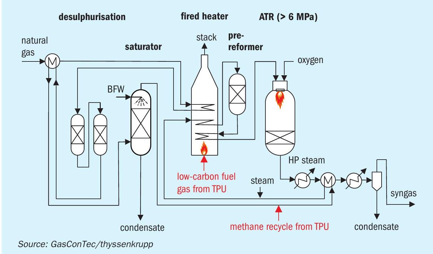
GasConTec and thyssenkrupp Industrial Solutions set out to jointly identify the optimum strategy and find the optimum solution for adding carbon capture to the AdWinMethanol® technology. AdWinMethanol® , like all members of the AdWin™ process family, includes a syngas generation island, the core of which is an oxygen-driven, high pressure catalytic partial oxidation reactor called “cPOX” or “ATR” (autothermal reformer). Fig. 1, shows the AdWin™ syngas generation process modified with the quite subtle changes required for carbon capture highlighted in red. The syngas produced is then converted into crude methanol in two sequential isothermal reactor stages, which is processed to product quality using a standard three column distillation system. AdWinMethanol® enables methanol production with considerable economic advantages, in particular at large capacities from 3,000 t/d up to 10,000 t/d, which can be single-train.
The key objectives for the new development were:
- capture 90% of the CO2 emitted from the methanol plant;
- minimise the penalty on plant efficiency;
- minimise the environmental impact;
- minimise the additional capex required;
- minimise the new technology risk (be innovative, but avoid unproven unit operations).
Three basic strategies to select from
The first, and perhaps most instinctive strategy to decarbonise methanol production, is to install a post combustion carbon capture (“PCC”) system in the flue gas path of the plant. Available PCC technologies include flue gas wash systems using solutions of MEA, advanced amines or cooled ammonia solution. Experience from various demonstration plants and in particular from the newer large-scale installations at Boundary Dam and Petra Nova has revealed the weaknesses of the PCC approach. In particular the use of MEA and advanced amines, when applied to pressure-less flue gases, has proven to be more challenging and less compelling than initially thought. The principal challenges include the following:
- Oxygen and oxidised components in the flue gas cause drastically increased amine degradation, which is at least one order of magnitude greater than that encountered with amine units used more conventionally in natural gas clean-up or refinery applications6,13 .
- Amine degradation products circulating in solution lead to the emission of critical volatile trace contaminants such as ammonia, piperazine, formaldehyde, nitrous amines and particularly undesired aerosol mists14,15 . To resolve these issues a sophisticated flue gas post-treatment system (water wash, acid wash) is required which inevitably adds complexity and cost. Any residual components that pass through the post-treatment system, will be emitted atmosphere. Moreover, degradation speeds up corrosion which in turn accelerates amine degradation13 .
- Operation of the amine plant has an impact on the overall efficiency of production. Modern amine plant designs result in a regeneration energy demand of 2.5-3.0 GJth/t CO2 . This translates to an estimated LP steam consumption of 125-150 t/h of LP for a plant cycling 1,800-2,000 m3 /h of amine solution to capture 2,500 t/d of CO2 from the flue gas of a 5,000 t/d methanol plant.
- Amine and amine plant effluent handling facilities increase the chemical and environmental footprint of the plant18.
- Amine make-up, contaminant removal, wastewater treatment and CO2 compression all add significantly to the operating cost19 .
In summary, adding a PCC system is technically possible, but has many drawbacks, in particular when looking at the environmental problems and risks associated with capturing CO2 from flue gases using amines and venting of the scrubbed gas to atmosphere. On this basis PCC was rejected as a strategy for integrating carbon capture to the AdWinMethanol® process.
A second alternative strategy is to install oxy-combustion technology on all of the plant furnaces. Oxy-combustion produces a flue gas rich in CO2 by combusting the carbon-containing fuels in a mixture of oxygen, from an air separation unit (ASU), and recycled CO2 . The idea seems compelling, as in modern methanol technology an ASU is readily available producing oxygen to feed the ATR. However, in order to keep combustion temperatures under control, as much as 80% of the CO2 captured has to be recycled and mixed with the oxygen to yield a moderated combustion atmosphere. As a result five times more CO2 is in circulation through the process than ultimately will be sent to battery limits impacting capex and opex. Moreover, the CO2 -rich stream contains excess oxygen, inert components, and other contaminants which have to be removed by means of a sophisticated oxy-fuel tail-gas treatment unit (TGTU), to meet the required purity specification for the export CO2 product stream21 . For these reasons the oxy-combustion option was also discarded.
The third strategy is to deploy CO2 removal in the pressurised syngas loop combined with ‘pre-combustion decarbonisation’ for the plant furnaces:
- The pressurised syngas loop of the AdWinMethanol® technology provides an attractive opportunity to remove the bulk of the CO2 with the least effort. Technology for the removal of CO2 from syngas is mature and widely available benefiting from more than 100 years of development with hundreds of references in operation at any scale.
- In pre-combustion decarbonisation, carbon-containing compounds are removed from the fuels prior to combustion. In essence, the plant furnaces in the methanol plant are fired with a hydrogen-rich stream, resulting in very low residual carbon emissions in the flue gas.
- The AdWinMethanol® process is ideally suited to the beneficial deployment of these techniques and as such has been selected as the basis for further development of a new and innovative methanol process with integrated carbon capture – AdWinMethanol CC® .
AdWinMethanol CC®
Within the two-staged methanol synthesis loops of AdWinMethanol® , CO2 is available at a high concentration and a high pressure. For the AdWinMethanol CC® process a tail gas processing unit (TPU) is added which replaces the PSA of the conventional AdWinMethanol® design (see Fig. 2).
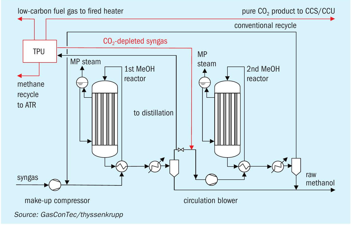
The TPU has the following functions:
- bulk removal of the CO2 from the syngas loop, whilst adjusting the stoichiometric ratio in the reactor feed to that required by the synthesis reaction;
- generation of a hydrogen-rich fuel gas for the fired heater;
- generation of a hydrocarbon-rich stream, recycled into the syngas generation feed stream;
- purification and compression of the CO2 to the required export quality and a pressure above 110 barg.
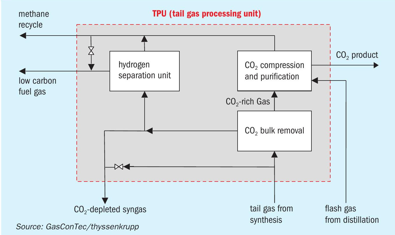
Fig. 3 shows the main components of the TPU. At the conditions prevailing in the syngas loop, CO2 can be efficiently absorbed by means of cold methanol, a liquid absorbent which is naturally and readily available on site. In the CO2 absorber, CO2 is physically absorbed by methanol and sent to the CO2 flash tower. Here, simple stepwise de-pressurisation releases the CO2 at descending pressure levels, simultaneously regenerating the absorbent, before it is cycled back to the absorber. No regeneration steam is needed. With the high CO2 loadings achieved, a solvent loop of only 850 m3 /h is required, which is 50-60% less than that of a comparable post combustion amine plant. The auto-refrigeration effect occurring during flash regeneration cools the methanol to the desired low absorption temperatures. Only a minor portion of the cooling duty has to be supplied by heat exchange against an evaporating refrigerant, which in this case can simply be liquid CO2 derived from the CO2 product stream. The resulting CO2 -rich gas stream is sent to the CO2 compression and purification unit, where co-absorbed gases are separated, traces of methanol removed, and the concentrated CO2 stream compressed to product pressure. Methanol-based CO2 capture systems as described here are not novel and have been used many times, for example, as part of Recti-sol® flow schemes. Indeed they are a common element of the technology toolbox of the AdWin™ process family.
The high pressure in the synthesis loop leads to compact equipment with sizes significantly smaller than those typical of an atmospheric amine absorber and regenerator loop. A small fraction of the CO2 -depleted syngas coming from the CO2 bulk removal is sent to a hydrogen separation unit (HSU), where it is split into a hydrogen-rich fraction and a hydrocarbon-rich fraction. The hydrogen-rich fraction is used as a fuel in the fired heater. The hydrocarbon-rich fraction is mixed with the stream of methane recovered from the CO2 compression and purification unit to form the methane recycle to the syngas island. As the hydrocarbon rich stream is the retentate from the HSU membrane system, it will have a pressure high enough to directly tie in to the synthesis gas generation feed. In the absence of any particularly stringent purity requirements, on both the hydrogen-rich stream and the hydrocarbon-rich stream, the separation can be done by a commercially available membrane system. For example, Air Product’s PRISM membrane systems are well-referenced for this kind of application. The hydrogen-rich fuel gas stream is the permeate from the membrane unit, with a low pressure, but still adequate for the burners of the fired heater. The balance of the CO2 -depleted syngas is fed to the second methanol reactor for further methanol production.
Production and consumption figures
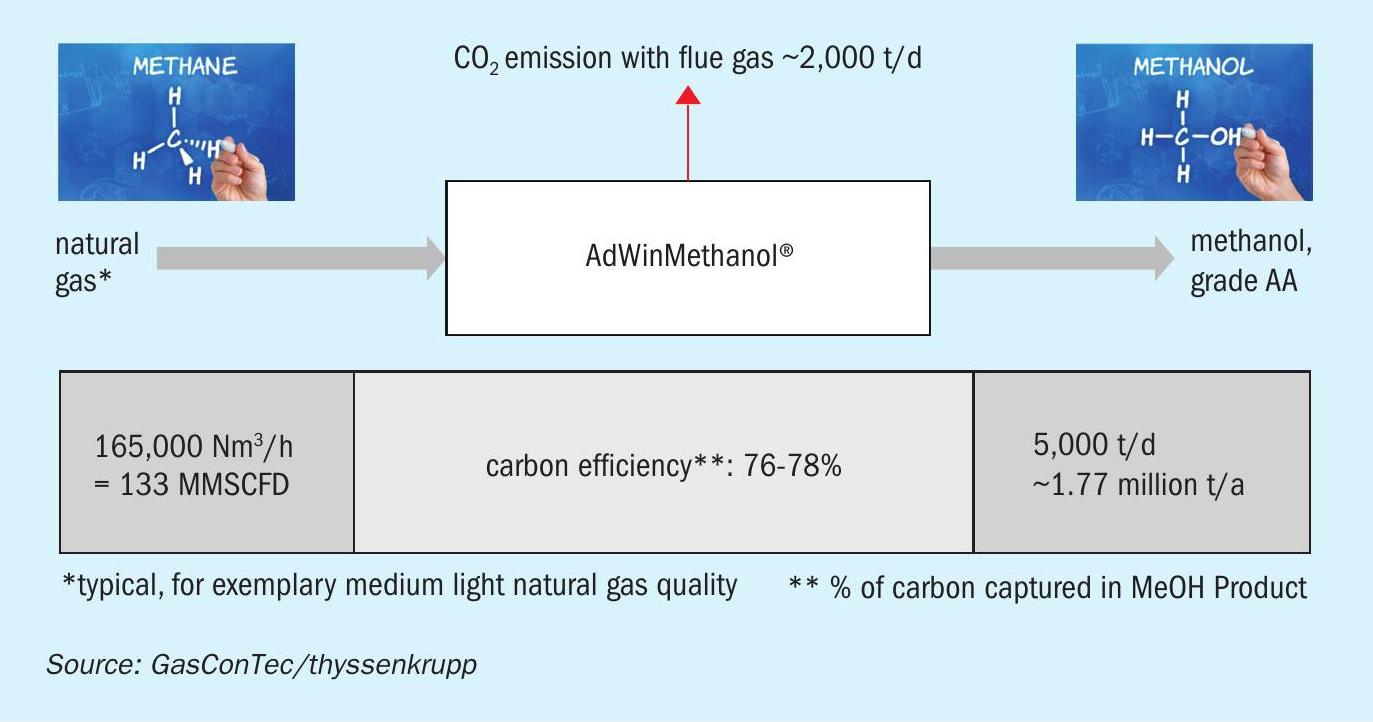
Fig. 4 shows the production figures of a 5,000 t/d high efficiency state-of-the-art AdWinMethanol® plant. Fig. 5 shows the same data for an AdWinMethanol CC® plant which has the same methanol production capacity, but delivers in addition a CO2 product ready for transport and utilisation or storage.
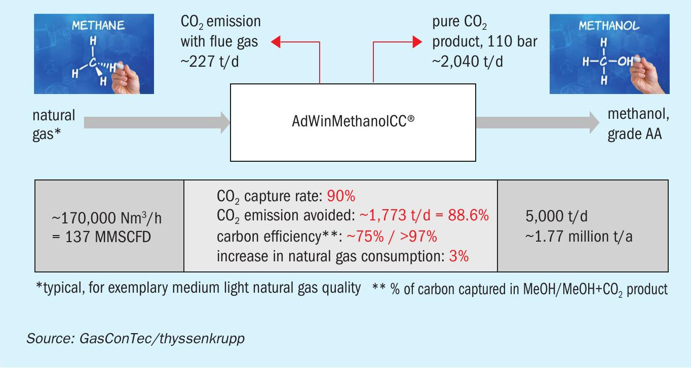
The CO2 stream sent to the battery limit of the AdWinMethanol CC® plant contains 90% of any carbon that does not end up in the product methanol. At the same time the plant has a slightly increased natural gas consumption, therefore the resulting overall reduction in CO2 emissions is 88.6%, if directly compared to the plant without carbon capture. All in all, 97.5% of the carbon in the natural gas fed to the plant is either captured in the methanol or in the CO2 product stream.
The AdWinMethanol CC® plant is equipped with an efficient, optimally integrated Rankine cycle using an off-the-shelf steam turbine/generator set and electric, frequency-controlled drives on all rotating machinery, including the ASU, syngas compressor and CO2 compressor. Consequently, the plant remains largely autonomous regarding electric power requirements meaning that import of electricity neither has to be considered in the energy efficiency nor in the carbon footprint of the plant. Due to the fact that readily available methanol is used as the solvent for carbon removal, no new chemicals have to be imported to operate the plant. Degradation of the methanol solvent does not occur removing the possibility of unwanted contaminants and emissions.
When it comes to comparing literature data on capture economics it is important to make sure that the battery limits are comparable, i.e. it is important to ensure that the capex and opex required to purify the CO2 and compress it to export conditions are included. AdWinMethanol CC® delivers the CO2 to battery limits as a pure stream, pressurised to 110 bar and ready for any utilisation or storage designation. This duty comes at a very low increase in natural gas consumption of 3%, compared to AdWinMethanol® which however, already boasts a 2-3% lower natural gas consumption compared to third party technology, such that the production efficiency of AdWinMethanol CC® is well within the ballpark of existing methanol synthesis technology without carbon capture. Because of the high pressure and small effective gas volumes, the TPU equipment arranged into the synthesis loop is compact and simple. The capex for the overall plant will increase with carbon capture, but mainly due to the cost of the CO2 compression and purification system, which is equally present in any CCUS installation, be it post- or oxy- or pre-combustion.
The resulting cost-of-emission-avoided will range well below $20/t of CO2 . Ultimately, economics will depend on the future CO2 emission certificate prices, however the resulting production cost will be highly competitive, once CO2 emissions come with a cost.
AdWinMethanol CC® also allows for a so-called capture-ready concept. Designing a futureproof plant to mitigate against future carbon emissions standards can be easily achieved by considering the minimum required design adaptions now, allowing for an easy conversion to AdWin-Methanol CC® later.
A complement to “green” methanol
“Blue” methanol does not compete against “green” methanol, but rather complements it. “Green” methanol from biomass will be markedly insufficient to satisfy global demand. In the long term, “green” PtM methanol, as available from thyssenkrupp Industrial Solutions AG, is more promising. However, as long as the availability of renewable power limits deployment, CCUS represents the most effective solution to drastically reduce the carbon footprint of methanol production.
Future PtM plants will create a demand for CO2 opening up the possibility of integrating an AdWinMethanol CC® plant with a PtM plant creating a winning combination, providing a zero-emission methanol production, whilst eliminating the need for CO2 transport and storage.
For example, the CO2 captured from a 5,000 t/d AdWinMethanol CC® plant could be used to produce an additional 1,490 t/d of methanol by means of a PtM plant consuming ca. 680 MW el of renewable electricity.
References