Fertilizer International 501 Mar- Apr 2021
31 March 2021
Cooling concepts for urea granules
FERTILIZER COOLING TECHNOLOGY
Cooling concepts for urea granules
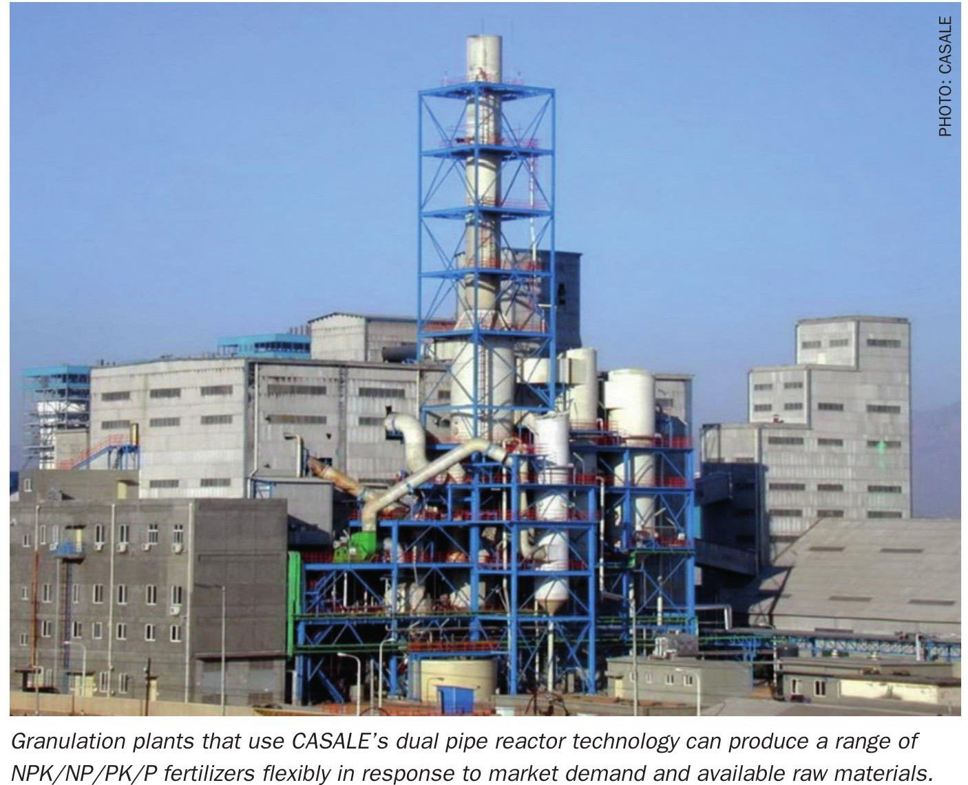
Globally, thyssenkrupp Industrial solution (tkIS) has engineered and built nine urea granulation plants during the last 10 years. Based on this experience, Benedict Jass, Marc Wieschalla and Ivo Mueller of tkIS describe two different cooling concepts for urea granules – fluid bed cooling and bulk flow cooling – and their contrasting advantages and disadvantages.
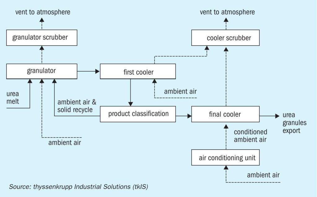
Urea granulation generally consists of four main process steps: granulation, cooling, product classification (screening) and off-gas scrubbing, as illustrated by the standard set-up in Figure 1.
The urea granules produced leave the granulator at temperatures slightly below 100°C. In the first cooling step, these are cooled down to an intermediate temperature to allow the granules to be properly handled – by bucket elevators or during screening, for example. As a next step, the granules are then classified, generating three size fractions: a fine fraction, the product fraction and a coarse fraction. The latter is crushed and recycled together with the fine fraction back to the granulator as seed material.
The product fraction contains those urea granules with the correct particle-size distribution. These are cooled down further in the final cooler to a temperature (e.g. 45-50°C) that allows stable and safe storage of the final product in a bulk hall.
The licensor thyssenkrupp Fertilizer Technologies (tkFT) offers the well-established and market leading UFT® fluid bed urea granulation process. Product cooling can be achieved as part of this process using different concepts, each having their own advantages and disadvantages. In standard set-ups, however, both cooling steps (Figure 1) are generally performed by fluid bed coolers, as described below.
Fluid bed coolers
Advantageously, for small- and medium-capacity plants, the first cooling step can be directly integrated into the granulator – delivering significant investment savings. Integration of the first cooler is not, however, recommended at higher production capacities, as this would lead to equipment transport difficulties and installation problems due to the granulator’s larger size. A separate first cooler is therefore still required in high-capacity urea plants.

The final fluid bed cooler has to be operated with dry air to avoid caking and lump formation in the cooler itself and during subsequent product handling and storage. Air drying is achieved using an air conditioning unit, with the evaporation of liquid ammonia within this unit providing the chilling necessary.
Bulk flow coolers
The bulk flow cooler (BFC) is an alternative cooling concept that can – in certain circumstances – replace the fluid bed as the final cooler. Essentially, the BFC is a plate heat exchanger, with cooling water on one side and free flowing urea granules on the other side. It functions as follows:
- The cooling water flows along enclosed channels in-between pairs of plates
- Evenly distributed urea granules are introduced at the top of the BFC.
- These flow vertically through gaps between the pairs of plates before being discharged at its base.
One of the main advantages of a BFC is that it operates by indirect cooling and, as a consequence, requires almost no maintenance and much less cleaning than a fluid bed cooler.
Operational experience
During the first five months operating a BFC at a urea granulation plant in Iowa in the United States, tkIS did not find it necessary to open the cooler for cleaning, despite several start-ups and shut-downs. Because of this, unlike other equipment (e.g. the urea granulator), washing is not foreseen as a regular procedure for this BFC installation. Nonetheless, if cleaning is eventually required, maintenance doors on the side of the BFC offer easy access. This enables heat exchanger plates to be pulled out for very simple cleaning or inspection during turnaround of the plant.
From a purely technical point of view, it should be possible to install BFCs widely at urea plants, as they are capable of providing sufficient cooling at all production capacities and scales. However, in practice, the successful installation and operation of this type of indirect cooling equipment will depend on various factors, as described below.
While BFCs require cooling water to operate – which is generally available at urea plants – they do not require a chiller unit to function, unlike fluid bed coolers (see Figure 1). The ability of BFCs to operate without an ammonia chiller is advantageous, as it eliminates the use of a potentially hazardous fluid at the urea granulation plant. Additionally, substituting a BFC for a fluid bed cooler, in the granulation plant’s final cooling step, eliminates other equipment items such as the final cooler fluidisation fan, as well as the air conditioning unit.
Advantages of BFCs for small- and medium-capacity plants
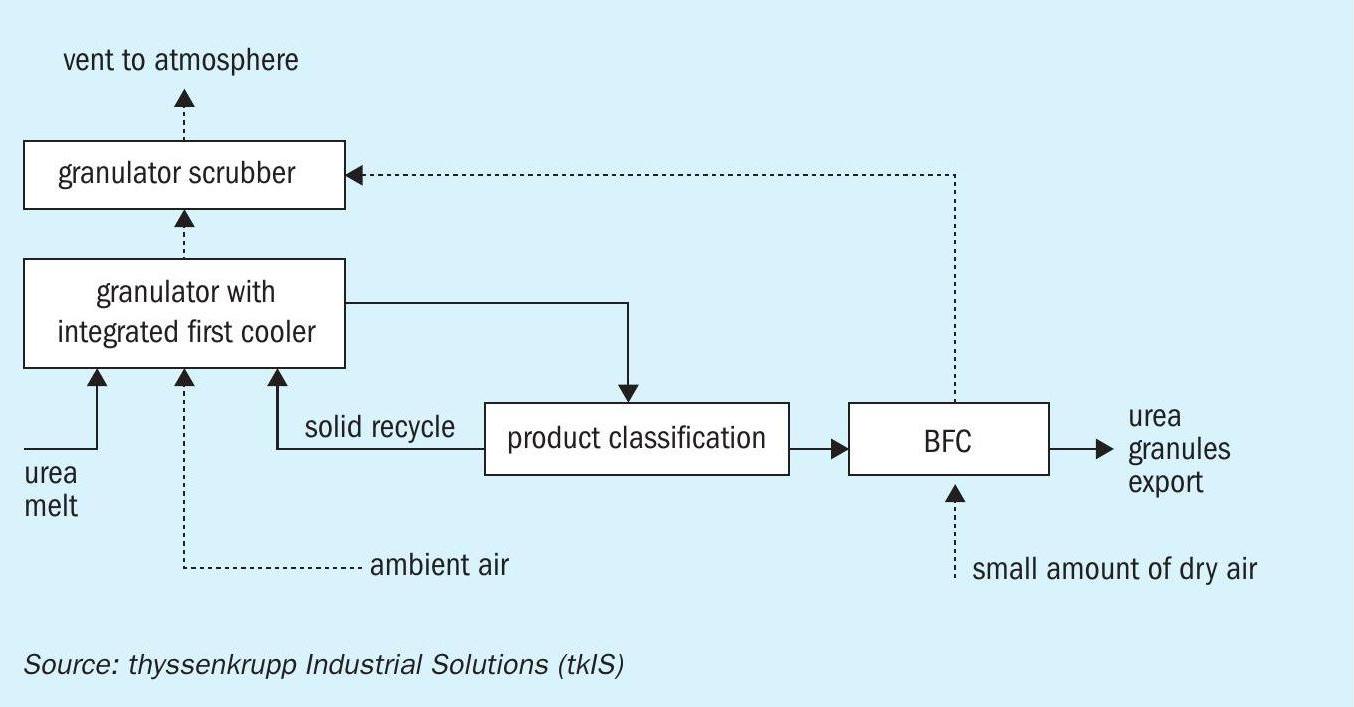
For the UFT® process, the greatest advantage of adopting bulk flow cooling can be achieved at small- and medium-capacity urea granulation plants (Figure 2).
In the process setup for plants of this size, the first cooler is incorporated into the urea granulator by extending the cooling area. This avoids the installation of the first fluid bed cooler and the corresponding fluidisation fan. Air used in this first cooling step is cleaned in the granulator scrubber alongside granulator off-gases.
In this configuration, replacing the second fluid bed cooler with a BFC eliminates the whole cooler scrubbing system – a cooler scrubber and a cooler scrubber exhaust fan – so reducing equipment and saving energy. The omission of the blowers alone cuts the electrical energy consumption of the granulation plant by around 3.5 percent. In addition, the absence of the air conditioning unit also reduces energy consumption by eliminating the power consumed in ammonia recompression.
Utilities: cooling water and purge air
The cooling water side of the BFC is operated as a circulating loop. Control of the cooling water inlet temperature is used to prevent the condensation of humidity on the surface of plates on the process side. Condensation can also be an issue during start-up and filling of the BFC. A heat exchanger is therefore used to bring the cooling water loop to the desired operating temperature before start-up of the BFC.
Although normally operated open, the cooling water loop is typically designed closed at high chloride concentrations. This is because the presence of chlorides in cooling water can lead to corrosion, particularly crevice corrosion and pitting, due to the elevated operating temperature on the cooling water side.
On the process side, purging is used to ensure the urea product flows freely though the inside of the cooler. The injection of purge air into the BFC helps prevent plugging and bridge building resulting from the adhesion of fine urea particles. As urea is a hygroscopic compound, it is important to prevent water, particularly humidity, from entering the BFC, as this can result in blockage of the cooler. This is achieved by controlling the dew point temperature of the purge air. This is effective at preventing both moisture condensation on the plates and moisture pick-up by the urea product.
In many regions, the ambient air is dry enough to be directly applied as purge air for much of the time. Where this is the case, the most economical option is to draw purge air directly from the existing granulator fluidisation fan. Because the ambient air was sufficiently dry, this was the solution chosen by tkIS for the BFC installed at the granulation plant in Iowa in the United States.
For time periods when – or geographic locations where – the moisture content of the ambient air is too high, the dew point can be lowered by mixing in an additional source of dried air, e.g. instrument or process air. Automatic mixing to control purge air dew point is even possible using ambient air temperature and humidity measurements to calculate the required flow rates.
The process air compressor of an ammonia plant can be used as a permanent supply of dry purge air in very humid or warm locations. Energy consumption can be kept to a minimum by taking air dry enough for use in the BFC at the lowest permissible discharge pressure. In contrast, using instrument air as a dry air source for the BFC will inevitably increase power consumption, as it generally needs to be dried to a much lower dew point.
Installation and layout requirements
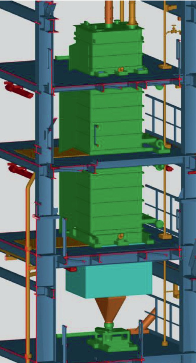
From an installation point of view, while the BFC occupies a smaller footprint area than a fluid bed cooler, it is both taller and significantly heavier (Figure 3). That can make the installation of a BFC cooler within the plant more challenging. On-site structural restrictions and operational requirements both need to be considered when assessing whether the dimensions of the cooler can be accommodated.
Cooler doors also need to be accessible so they can be opened to allow the exchange of cooler plates. The height of BFCs means elevated platforms are required to enable single modules to be reached. Should blocking of the BFC occur on the process side, the upper part of the cooler also needs to be accessible for flushing by water hose. A washing area at each plate bank (indicated in brown in Figure 3) is therefore needed for cleaning purposes.
In circumstances where only a small BFC design is necessary, e.g. for urea plant revamps, the cooling water can be actively cooled (chilled).
Effect on product characteristics
During the granulation process, both the classification of the product and transport under gravity result in the formation of dust which then adheres to urea granules. Fluid bed coolers, in addition to their cooling function, also have a valuable de-dusting effect on urea granules. Hence, products generated by a plant configured with a fluid bed as a final cooler will tend to be less ‘dusty’.
Using a BFC as the final cooler instead of a fluid bed type could, therefore, potentially lead to a change in product characteristics. But experience gained during commissioning has demonstrated that bulk flow cooling does not, in fact, have any measurable negative effects on product quality. Indeed, the perceived problem of higher dust adhesion to urea granules can be addressed by good ventilation and installing sufficient de-dusting spots during material handling.
Energy consumption case study
Which of the two cooling concepts, the fluid bed cooler or the BFC, is the most suitable type for the final cooling of urea granules is subject to much debate. The answer clearly depends on which parameters are used to measure their relative performance. Any assessment must also involve detailed monitoring. One comparison, for example, could be based on their relative operating costs, which is linked in turn to power consumption.
As already stated, the fluidising air for the fluid bed cooler must be dry so that the urea does not pick up humidity. Application of cooled dry air also ensures an economical design. The air conditioning (drying and cooling) is done using an air chiller unit supplied by ammonia sourced from the ammonia plant. But how much energy is consumed by a chiller unit during the course of a year? That depends on factors such as the production site’s temperature profile.
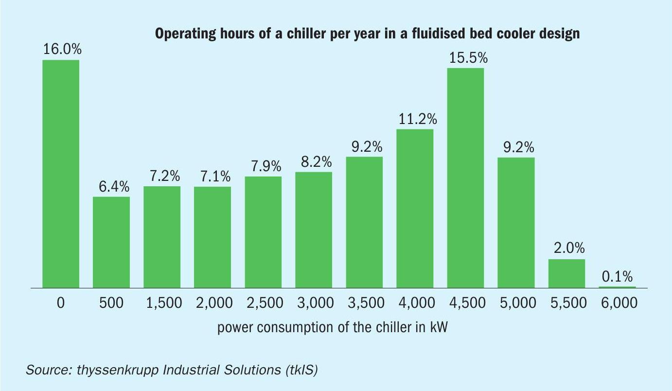
Figure 4 shows the annual operating hours of a fluid bed chiller in percent (y-axis) against power demand in kW (x-axis) for a fictitious US Gulf Coast site with a capacity of 3,500 t/d. This chart shows that the fluid bed chiller is only operated at full load (6,000 kW) on a few days, while for the majority of the year the chiller operates using only a fraction of its total cooling capacity.
Overall, we calculate that the fluid bed cooler concept requires approximately 950 kW, including the required chilling duty and fan power. In comparison, for an otherwise similar plant, using a BFC for cooling would result in an average energy consumption of approximately 140 kW, assuming the BFC is supplied purely with dry air. This calculation takes into consideration the production of dry purge air and cooling water pumping. Therefore, by comparing power consumption alone, the BFC clearly wins the race in this case study.
Conclusions
The use of a bulk flow cooler instead of a fluid bed cooler can provide a good alternative in the final cooling of urea granules. Nevertheless, many parameters require evaluation before deciding which solution best fits the client’s specific requirements.
In our view, implementing bulk flow cooling as part of the granulation process also requires an experienced engineering contractor. thyssenkrupp Industrial Solutions has valuable experience of using bulk flow coolers, at both new-build urea plants and during urea plant revamps. tkIS also has long-term experience in cooperating with the urea granulation licensor tkFT. Together, these capabilities ensure that, for each individual urea granulation plant, the best cooling concept is selected and implemented.