Nitrogen+Syngas 371 May-Jun 2021

31 May 2021
RectisolTM column design with structured packings
GAS CLEANING TECHNOLOGY
RectisolTM column design with structured packings
By using a Rectisol™ demonstration unit at one of Air Liquide’s industrial production sites, Air Liquide Engineering & Construction has gained unique know-how in Rectisol™ column design with structured packings. S. Schmidt, R. Szabo, M. Linicus and S. Corbet report on how the application of commercially available structured packings in the absorber columns of a Rectisol™ unit results in significant capex and opex savings.
Rectisol™ gas cleaning technology is the leading technology for providing high purity syngas for applications such as methanol, ammonia, Fischer-Tropsch fuels and synthetic natural gas (SNG), as well as hydrogen. The Rectisol™ process uses methanol as a solvent for the selective removal of CO2 , sulphur (H2 S, COS) and various trace components (NH3 , HCN, CS2 , mercaptans, BTX, metal carbonyls). Air Liquide has more than 110 references where Recti-sol™ units have been deployed worldwide, as well as operational experience from its own production plants1 .
In the Rectisol™ process, the absorption takes place under high pressure and low temperature, i.e. process conditions that are favourable for absorption. The temperature in the absorber can be as low as -75°C, the pressure is typically higher than 30 bar. At this pressure level, the hoop stress of the column is considerable and the required shell thickness is correspondingly high. If the diameter of the column is reduced, the hoop stress is decreased, which leads to reduced capital expenditure for the absorber. As the absorber represents up to 10% of the total equipment costs for a Rectisol™ unit, the benefit of size reduction is clear.
For most projects, the remote location of the plant site imposes a limit on the capacity to transport the sizeable equipment by road. This often results in a parallel absorber setup, instead of a setup with just one absorber above the transportation limit. Absorber diameters above this limit have to be avoided to prevent additional cost.
Traditionally, absorber columns have been designed with trays. However, structured packings in high pressure absorber columns offer considerable advantages over trays making them of interest within absorption applications. These advantages include lower pressure drop and a larger active area (no downcomer), enabling the processing of higher liquid loads. Illustrations of trays and structured packings are shown in Fig. 1.

Fig. 2 shows a simplified setup of a Rectisol™ unit. Raw syngas enters the absorber column and is processed subsequently in the different absorption sections for sulphur removal (H2 S, COS), CO2 bulk removal sections (CO2 cooling section and CO2 main wash section) and CO2 fine wash section. The laden solvents are then sent to the flash regeneration sections, in which high purity CO2 ready for use or storage is produced. Afterwards, the solvent enters the reabsorber column. In the reabsorber, the remaining CO2 is stripped out with nitrogen under low pressure (stripping sections) and flashed-out sulphur components are “re-absorbed” again (hence the name) and routed to the hot regeneration section, where the solvent is cleaned of any remaining sulphur components and an H2 S rich stream is generated.


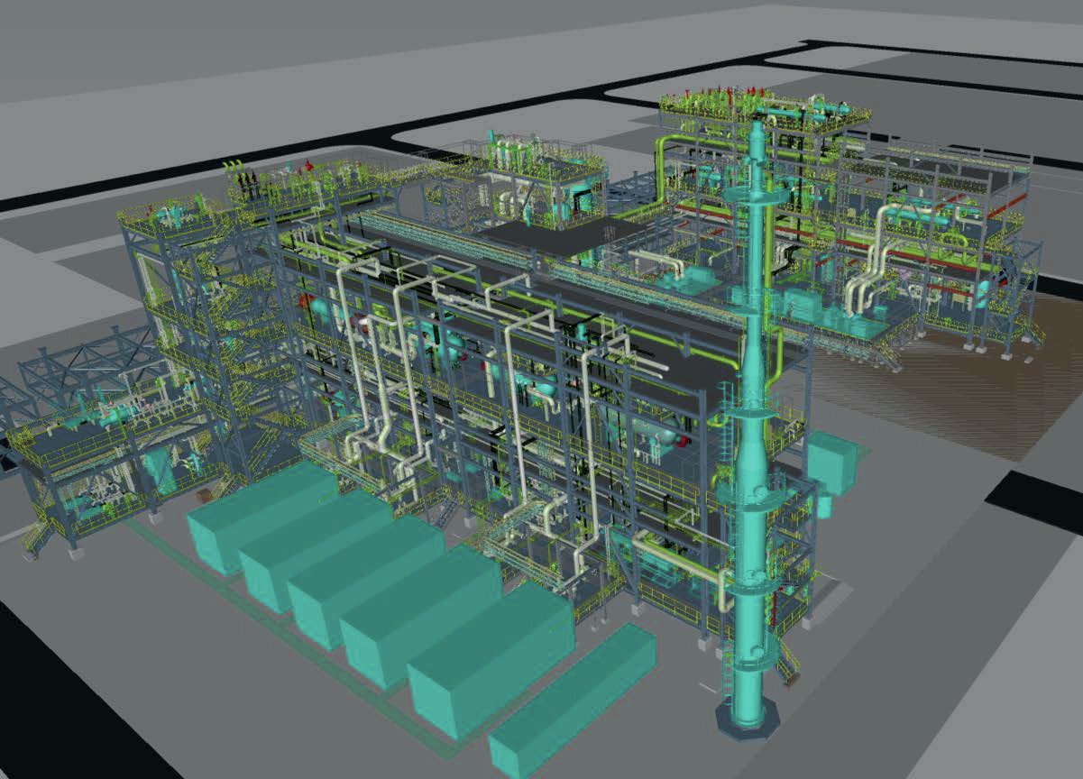
The lean solvent is then recycled back to the absorber after cooling and re-used for absorption. To investigate the performance of structured packings within Rectisol™ technology, Air Liquide designed and installed a demonstration unit at one of its industrial production sites (Fig. 2 lower section and Fig. 3). The Rectisol™ Demonstration Unit (RDU) is operated in bypass to an industrial Rectisol™ unit and is thereby able to operate under real process conditions.
Liquid and gas streams from the absorber and reabsorber of the industrial production unit can be withdrawn at different locations via 25 different tie-in lines, processed and tested at the RDU and finally routed back to the production unit2 . During the test campaigns at the RDU, performance data for different structured packing types in the absorber and reabsorber sections have been gathered and column design rules developed.
Fig. 4 gives an overview over the tested Rectisol™ sections with their typical flow regimes. The ranges for liquid and gas loads for the different operation sections differ widely. While the three CO2 absorption sections feature high liquid loads with flow parameters between 1 and 3, the reabsorption sections show lower liquid loads with lower flow parameters of 0.05-0.7. To show the exceptionally wide operating range of the columns within a Rectisol™ unit, the flow parameters for high-pressure distillation are in the range of 0.1-0.33 . As a reference for structured packing performance, the capacity data for typical structured packings4 are also shown in the diagram. It can be observed that the loadings of the different sections have to be addressed by packings with high capacities.

In this article, the impact of the application of structured packings within a Rectisol™ unit is evaluated in relation to two different aspects: first, the diameter reduction potential of the absorber is evaluated.
Second, the application of structured packings within the absorber and reabsorber is simulated for an industrial as-built plant. The operational and capital expenditures (opex, capex) are then compared to the actual as-built plant.
Results: diameter reduction
To evaluate the diameter reduction for Rectisol™ absorbers with structured packing design, two designs were prepared for 16 different feed gases from actual projects. One design featured a standard tray design, the other a structured packing design based on the know-how generated by the RDU. The gas capacity ranged from 180 kNm³/h-900 kNm³/h, pressure ranged from 35-55 bara and CO2 content in the feed gas ranged from 25-35 mol-%. For a fair comparison, both designs have been conducted using widely commercially available mass transfer internals.


Fig. 5 shows a normalised absorber diameter against the feed gas capacity for trayed and structured packing design. Most importantly, the diameter reduction by using a structured packing design compared to a tray design is around 25%.
Additionally, Fig. 6 indicates the typical downstream applications of a Rectisol™ unit for the respective gas capacities, such as hydrogen production (for blue hydrogen with carbon capture and storage, ammonia production, power block or refinery applications), methanol synthesis, Fischer-Tropsch fuels, waste-to-fuel/biomass-to-fuel applications or synthetic natural gas (SNG).
Results: optimisation of the Rectisol™ unit (opex & capex)
To investigate the overall savings in opex and capex, a Rectisol™ unit with a gas capacity of 200 kNm³/h was simulated assuming structured packings as mass transfer internals for the absorber and reabsorber. In comparison to using trays in these columns, the structured packing design has the advantage of reduced pressure drop, higher separation efficiency (lower HETP) and the aforementioned higher liquid loads. The increased separation efficiency leads to reduced liquid flows requiring smaller equipment as well as decreased pump duties and steam consumption for solvent recovery. At the same time, the smaller pressure drops enable the operation of the regeneration part at lower pressures which leads to higher cold recovery and less refrigeration consumption.
As a reference, this setup was compared to an industrial as-built plant with tray design for both the absorber and reabsorber. The opex was evaluated using utility costs for a Chinese location. The capex for both cases were also evaluated on a high level basis.
The outcome for the absorber with dedicated sections for CO2 , H2 S and COS and trace component removal is summarised in Fig. 6.
The diameter of the structured packing absorber is 73% compared to the trayed absorber column (100%). At the same time, the volume of the column is decreased. It should be noted that the height of the column is also slightly decreased as a result of the reduced height required for structured packing and also because of the slightly reduced solvent flows leading to less height being required for the liquid levels in the column.
Fig. 6 also shows the capital cost savings if a structured packing design for an absorber is used instead of a conventional tray design. The absorber capital cost for the structured packing design is given as a fractional cost of the trayed design. It can be observed that the cost for the internals are almost the same for both options (8% vs. 7%). However, the cost for the high-pressure service shell reduces drastically for the absorber with the smaller diameter. In total, compared to the trayed design absorber, the capital costs for the structured packing absorber is 61%.
In terms of opex reduction, the application of structured packings in the reabsorber leads to reduced pressure drop and higher separation efficiency. The lower pressure drop is beneficial for the operation of the solvent regeneration, as it allows it to operate under lower pressure and leads to higher cold recovery by flashing of CO2 and less steam consumption for solvent recovery. Additionally, less electricity is required for pumps due to the lower operating pressures in the regeneration section. All in all, the application of structured packings within the Rectisol™ unit results in 17% opex savings, including savings for refrigeration duty of 19%, electricity 16% and steam of 18% compared to the case with the tray design. Taking account of the indirect CO2 emissions arising from steam and electricity, 16% less CO2 is emitted.
Due to the reduced solvent flow rates and the smaller absorber, the size of other equipment is also reduced, resulting in an overall capex reduction on the Rectisol™ equipment of 7%.
Air Liquide Engineering & Construction is able to tailor Rectisol™ column design to the needs of its clients. It should be noted that the benefits as evaluated and presented above can be obtained by implementation of state-of-the-art, widely available structured packing as mass transfer internals. Air Liquide Engineering & Construction is also able to apply sophisticated high capacity internals which will give an even more competitive design.
Summary
With their Rectisol™ demonstration unit, Air Liquide Engineering & Construction has unique know-how in Rectisol™ column design with structured packings. The application of commercially available structured packings in the absorber column leads to a capital expenditure reduction of 39%, following an absorber diameter reduction of 27%. Further application of structured packing within the reabsorber column results in operational expenditure savings of 17% due to the decreased operating pressure of the regeneration system. Owing to the reduced solvent flow rates and the decreased equipment sizes, a total capital expenditure reduction of 7% for the whole Rectisol™ unit equipment is accomplished.
References