Fertilizer International 506 Jan-Feb 2022
31 January 2022
Optimising phosphate production
PROCESS TECHNOLOGY
Optimising phosphate production
Phosphate manufacturing is being enhanced thanks to process integration, digitalisation and other advances.
JESA TECHNOLOGIES, WORLEY
Integrating benefication and phosphoric acid plant designs
As the world population grows, so does the need to produce more food. Phosphate and other fertilizers help feed the world by making farms more productive by boosting per hectare crop yields. As a consequence, fertilizer demand continues to rise driven upwards by population growth.
While production plants can typically operate decades beyond their original end-of-life, there will always be an ongoing need for new phosphate plants to satisfy current and future fertilizer demand. This applies to both brownfield projects – which improve the efficiency and output of existing production plants – and greenfield projects able to benefit from modern techniques and technologies.
All projects are subject to economic pressures. And, in a mature industry, even small improvements to plant design can deliver large results and economic dividends. This is especially true of modern, large-scale, world-class plants.
When it comes to investment costs, merging the design of both the beneficiation and phosphoric acid plants into one project – with a single design firm taking responsibility for both – presents a major opportunity. As we discuss here, this allows designers to work together in synergy, pool efforts and use a feedback loop to optimise project economics.
Taking account of variability
What often makes phosphate production so interesting for those within the industry is the simple fact that phosphate ore bodies around the world are vastly different. This means that individual phosphate rock types behave very differently in beneficiation and phosphoric acid plants. Out of necessity, different plant designs are therefore required to accommodate these wide ranging ore characteristics.
Also, there is always some inherent variability within a single phosphate ore body. The degree of variability can also differ between projects, making the installation of additional unit operations necessary in some cases. Consequently, a generic design, unless it is able to adapt to the specific ore and the local constraints encountered, will be doomed to fail on project economics for a variety of reasons. Furthermore, the fallback option (debottlenecking) can take years of trial and error, if carried out in the field after mechanical completion. Ensuring that the correct approach to phosphate plant design is taken at the outset is therefore critical for meeting the owner’s goals.
Phosphate rock concentrates
The design of a phosphate production plant requires a dual test programme – for the beneficiation plant and phosphoric acid plant, respectively. Typically, the phosphate rock is analysed and bench-scale beneficiation tests are carried out. The results obtained are then used to develop a pilot plant flow sheet to validate the original bench tests. Following on from this, phosphate rock concentrate from the beneficiation pilot plant is used as feed for the phosphoric acid pilot plant. Results of these pilot tests are then used to design the phosphoric acid plant.
This is a high-level view of what in practice is a detailed process. Nevertheless, the main point here is that the dual test programmes complement each other. Normally, these tests are done individually to meet set goals provided by the owner.Yet, if done jointly, these goals may be iterated to help optimise the whole project – not just one area of the plant. In other words, what if the concentrate generated by the beneficiation plant was a variable for the designers rather than being a fixed point?
Beneficiation plant design
Many factors will influence flowsheet development for a phosphate beneficiation plant. Of overriding importance are both the owner’s objectives and local site-specific constraints – as these form the basis of the design. Yet it is the – seemingly endless! – equipment combinations that will ultimately define the flowsheet. Configuring the equipment correctly is an essential consideration due to differences in the ore bodies encountered. Especially as the techniques used to cater to respective ores around the world differ too.
In beneficiation plant design, owners will set four primary objectives:
- Throughput
- Grade
- Recovery
- Cost.
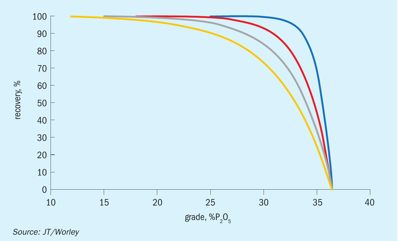
These potential variables are routinely shared with the phosphoric acid plant designer for feedback. Yet the room for manoeuvre is limited, given that the owner will normally specify the grade and/ or recovery. These two variables are not mutually exclusive either. Instead, there is typically a trade-off between grade and recovery, as shown generically by the family of curves in Figure 1.
Many factors can affect the shape of these grade-recovery curves, e.g., ore grade, mineralogy and particle size, to name a few. The shape of the curve for a particular ore is initially determined from bench testing and later confirmed by pilot testing. After the completion of the beneficiation tests and design work, there is normally an evaluation of the trade-off between grade and recovery versus capex and opex.
The preliminary flowsheet for bench-scale beneficiation is then drawn up based on this information, alongside site information and knowledge of similar ores. Adjustments are made to this flowsheet as test data becomes available and unit operations are defined. Targeted techniques for the removal of gangue minerals are largely identified based on the chemistry of the rock. The grade-recovery curve is then established by combining all the test data obtained from the process flowsheet.
Because the concentrate grade is normally specified by the owner, recovery is the main output of bench- and pilot-scale beneficiation tests. The design of the beneficiation pilot plant is modular and can therefore be arranged according to the original bench-scale flowsheet. In this way, the pilot plant can test and confirm the hypotheses generated during bench-scale testing.
For the designer, one advantage of doing testwork is that it allows modifications to be made during the pilot plant run, i.e., the pilot plant is not necessarily fixed. Since the plant is modular, modifications can be made during the test if a parameter is not being met, allowing additional data points to be evaluated. This eliminates the necessity for additional test runs that would occur in a lab operating without designers making real time assessments.
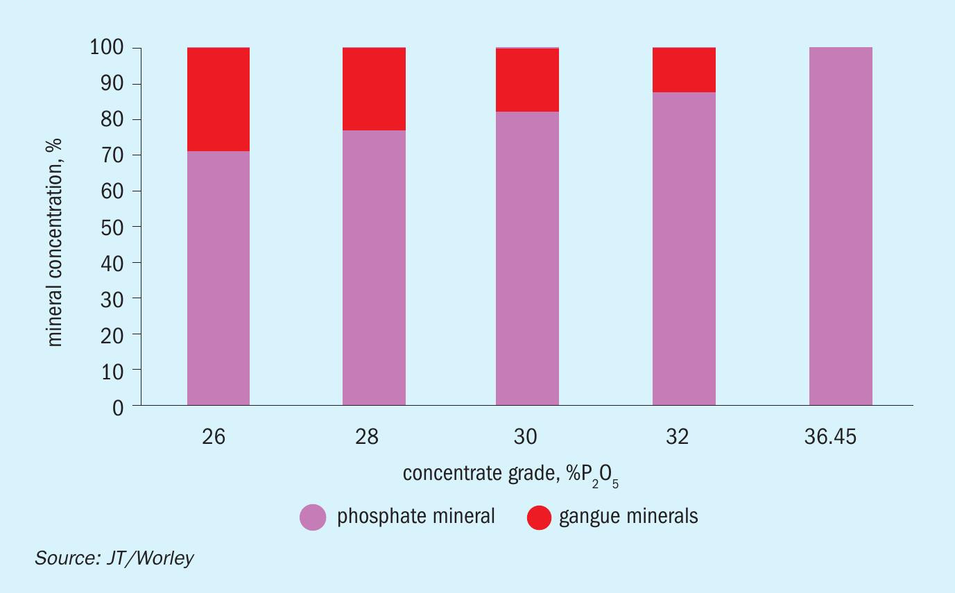
Making grade a variable
The concentrations of phosphate minerals and gangue minerals are a function of concentrate grade, as shown in the generic chart in Figure 2. This chart illustrates the opportunity that exists for an integrated approach to optimising beneficiation and phosphoric acid plant design. This can be achieved by evaluating the impacts of accepting greater concentrations of gangue mineral in the rock concentrate feed to the phosphoric acid reactor – i.e., by making grade a variable.
The impacts of varying concentrate grade can be evaluated through integrated beneficiation and phosphoric acid testing and design. If the designers are working in the same testing facility, they can communicate directly with one another in real time, instead of via intermediaries, so avoiding the risk of miscommunication and the loss of intentions and subtleties.
Phosphoric acid plant design
The key drivers for a phosphoric acid plant project are client objectives, local constraints and ultimately economics. Client objectives include:
- Throughput: Production capacity is the obvious and foremost design point – being the basis for which equipment is sized and arranged.
- Yield: This is a function of the rock but can be influenced by the design of the plant, especially when considering global recovery.
- Flexibility vs operability: These tend to be at odds due to the relative merits of a simpler design versus a more complicated design. While the latter requires operations to be more precise, it does allow more opportunities to make changes without loss of production.
- Environmental concerns: These are becoming more and more of a design driver.
- Robustness of the design: This relies on materials of construction, a sparing philosophy, and other means of ensuring the plant has a high operating factor.
- Synergies: There are potential synergies in a production complex. The phosphoric acid reactor, in particular, is often seen as a place where everything can be recycled, although there is an equal need to ensure the chemistry of the process is not altered and compromised.
- Capex/opex: Both are highly visible drivers.
All of the above points need to be discussed and then cleared for compatibility with the owner’s direction to the design team. Local site-specific constraints include:
- Water: This is arguably the single most important constraint as it defines recycles, potential discharges and plant efficiencies.
- Plot plan: This should not be underestimated and can cost the owner considerable capital if not defined by an experienced engineer. A well laid out plot plan can enhance operations and maintenance activities as well as saving capex and opex.
- Environment: Is winterisation needed, is it a zero-discharge design, will the water balance be positive or negative?
- Process route: Different process routes for phosphoric acid deserve consideration as each one has a place. What is the goal for production, is the facility vertically integrated or will merchant-grade acid be the product?
- Product quality and rock feed: Last but not least, the concentrate feed will define a large part of the process.While the concentrate feed from the beneficiation plant is normally a given, the key point of this article is that treating it as a variable instead can lead to the betterment of the whole project.
The importance of concentrate feed
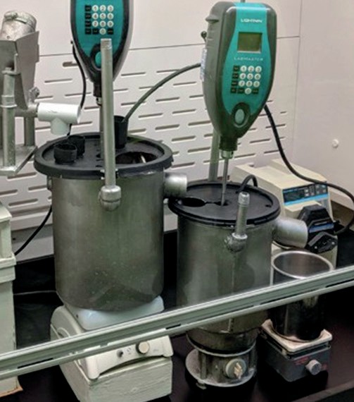
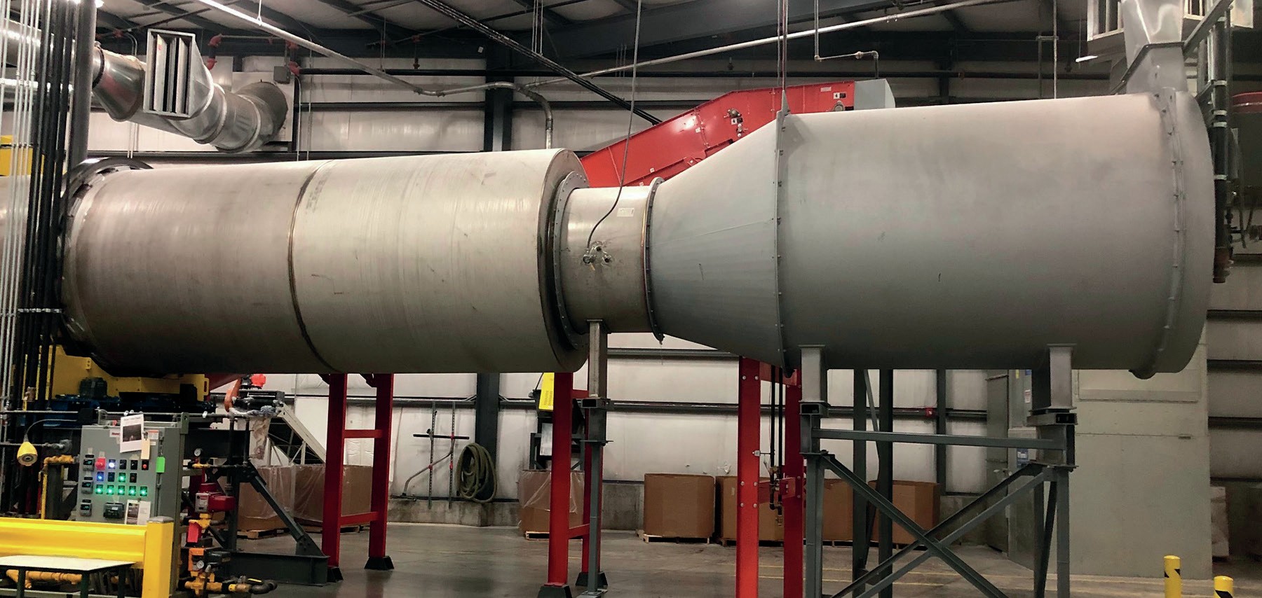
The concentrate is fed into the phosphoric acid pilot plant (see photo) to determine equipment sizing parameters such as:
- Reactor volume
- Filter size
- Specific gravities
- Viscosities
- Vapour pressures
- Consumptions
- Chemical splits
- Gypsum properties
- Particle size distributions
- Specific heat
- Bulk density.
Size distribution also affects the crystal habit in the reactor. Our main premise is that – if the feed is allowed to be variable – these parameters can be adjusted to the benefit of the project.
An experienced designer will be aware of how the following changes in the chemical content can affect the process:
- Aluminium deficiency can result in low filtration rates
- High iron affects global recovery
- Magnesium affects scale rates
- Calcium affects sulphuric acid consumption.
Other minor impurities can also play a major role, as the chemistry throughout the process is quite complex. Again, our point here is that the phosphoric acid plant designer is well equipped to ‘negotiate’ these impurity levels – if allowed to go back and liaise with the beneficiation plant designer.
Synergies and integrated working
By making the phosphate rock concentrate a variable, and enabling beneficiation and phosphoric acid plant designers to work together closely, a valuable feedback loop between the design teams is created. Although it might may take a few iterations, real savings could well be realised, in our view, if the concentrate were able to be adjusted as a matter of course.
For example, if the phosphoric acid plant can meet its performance goals with a lower grade concentrate than the target set in beneficiation, then the capex on the beneficiation plant is probably excessive. Conversely, if the phosphoric acid plant is experiencing severe problems due to the presence of an impurity, then higher capex on the beneficiation plant may well have been justified to lower the capex on the phosphoric acid plant.
Put simply, the investment cost required in the beneficiation plant rises as the investment cost of the phosphoric acid plant decreases, and vice versa. Finding the lowest overall capex should therefore be the overall project goal. This can be achieved through pilot-scale iterations to discover the inflection point between the respective plant investment costs.
There are some obvious opportunities for synergies. The particle size fed to the phosphoric acid reactor is one notable area. Milling is almost always required in the beneficiation plant. So, sizing their milling operations to accommodate milling requirements of the phosphoric acid plant could either eliminate the downstream need for milling or greatly reduce the loading. Increasing the grade of the concentrate, meanwhile, or taking advantage of the ore’s reactivity, could reduce the reaction volume required in phosphoric acid production. Also, if an ore does not filter well, there are beneficiation techniques available to improve these rates – enabling the active filtration area to be reduced.
Additionally, reducing calcium in the phosphoric acid plant feed will lower sulphuric acid consumption, as well as the heat load in the system. This is advantageous as it results in smaller equipment and lower water flows. Heavy metal removal, by reducing viscosity, also aids filtration as well as clarification. Benefits would almost certainly accrue if the beneficiation and phosphoric acid plants both shared a water balance. While the two plants do not necessarily need to be proximate for synergies to take place, more opportunities will exist if this is the case.
Certainly, when it comes to synergies, chemistry is at the crux of the matter. Additionally, there are many other site-specific constraints that could be targeted depending on the circumstance.
Conclusions
In our view, by having both plant design teams working together under the same roof, the above points can be addressed routinely and without interruption. This can also save time during project schedules that rarely allow the synergies between the beneficiation and phosphoric acid plants to be examined in the way described here.
The design philosophy set out in this article offers real opportunities, in our view, especially in a mature market where minor improvements can result in large returns. These opportunities are, however, not always obvious. Only test work is likely to reveal them, making it difficult to quantify or predict the synergies at the outset of a project. Despite this, synergies can be pursued as part of a value-added exercise during projects.
Indeed, an experienced and adept design team will always look to add value for the owner. In fact, this concept is at the core of how Jesa Technologies (JT) executes projects. With pilot plant facilities for both beneficiation and phosphoric acid – and licensed technology for each of these plants – JT offers exactly the unified approach needed. Our integrated project approach allows us to delve deep into value-added opportunities across these plants. Furthermore, since phosphate fertilizer plants will typically be operating for 20-50 years or more, getting the design right, up front, will deliver benefits to the owner for years to come.
PRAYON TECHNOLOGIES
Improving phosphogypsum quality using a soft sensor
The Prayon case study
Data generated by any phosphoric acid plant will contain worthwhile and actionable information. Indeed, by managing and analysing such data, a decision support system can be established by introducing new variables know as ‘soft sensors’. These can provide real-time information on the performance of the phosphoric acid plant, its maintenance status, and even the quality of the products generated.
Prayon has implemented a specific programme on data management to get the best from one of its own phosphoric acid production plants. The overall objective was to develop a new decision support tool. This was based on the collection and analysis of data and the identification of links between this information.
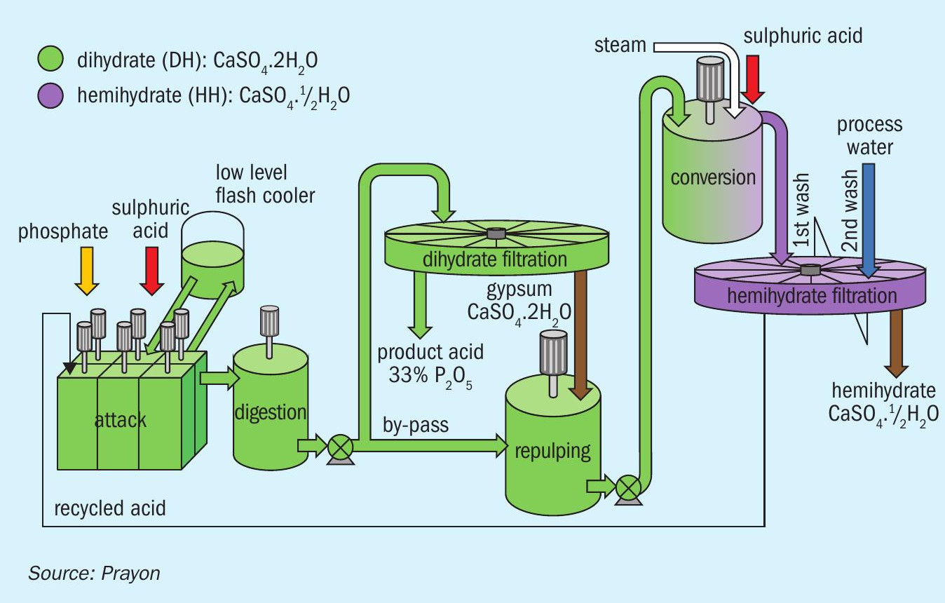
The Central Prayon Process and calcium sulphate quality
Prayon’s phosphoric acid plant in Engis, Belgium, operates using the highly efficient Central-Prayon Process (CPP, Figure 1). This combines a double crystallisation process with a double filtration step to produce phosphoric acid at high P2 O5 recovery as well as a pure calcium sulphate co-product.
The main advantages of CPP, versus other phosphoric acid technologies available on the market, are as follows:
- It offers the highest level of P2 O5 recovery (> 98%) from the phosphate rock raw material
- It generates phosphogypsum with the lowest P2 O5 content
- This phosphogypsum is self-drying – achieving a final moisture content as low as 10 percent, without the use of a dryer.
Due to environmental legislation, the stacking space for gypsum at Engis is both limited and strictly regulated. To comply with these constraints, and due to its high purity, most of the phosphogypsum produced at Prayon’s Engis plant is turned into a valuable co-product (‘valorised’) and re-used for applications such as plaster, cement and agriculture.
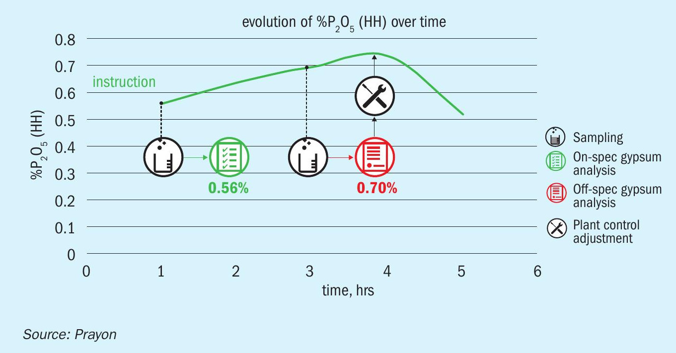
The quality and purity characteristics of phosphogypsum needs to be maintained at a high level if it is to be valorised in the plaster or cement industry. In particular, the P2 O5 content in the calcium sulphate hemihydrate cake needs to be continuously monitored and kept below 0.6 percent. Additionally, while the on-specification (‘green’) gypsum can be transferred to the plaster company, off-specification (‘red’) phosphogypsum must be diverted before being conveyed to the gypsum stack.
Operators flying blind
Prior to the implementation of the data management programme, it was not possible to monitor the quality (% P2 O5 ) of the hemihydrate cake generated by the CPP process in real time. This was due to the interval between gypsum sampling and the added delay in receiving results from the analytical laboratory.
At Engis, gypsum samples are generally collected and sent for analysis every two hours, with the results from the laboratory then available one hour after sampling. Because of this time lapse, operators are effectively ‘flying blind’ for much of the time and, due to this lack of data, are unable to correct the process for hours. This can lead to a shortfall in process performance, potentially resulting in the production of off-spec gypsum (>0.6% P2 O5 ) for around three hours (see Figure 2).
The answer – a ‘soft sensor’
The answer to this problem was to identify and create a ‘soft sensor’ The aim was to predict the P2 O5 content in the cake from a set of data in real time (see methodology in Figure 3). This would then allow the plant operator to take corrective action earlier, based on the soft sensor prediction, instead of waiting for the laboratory results.
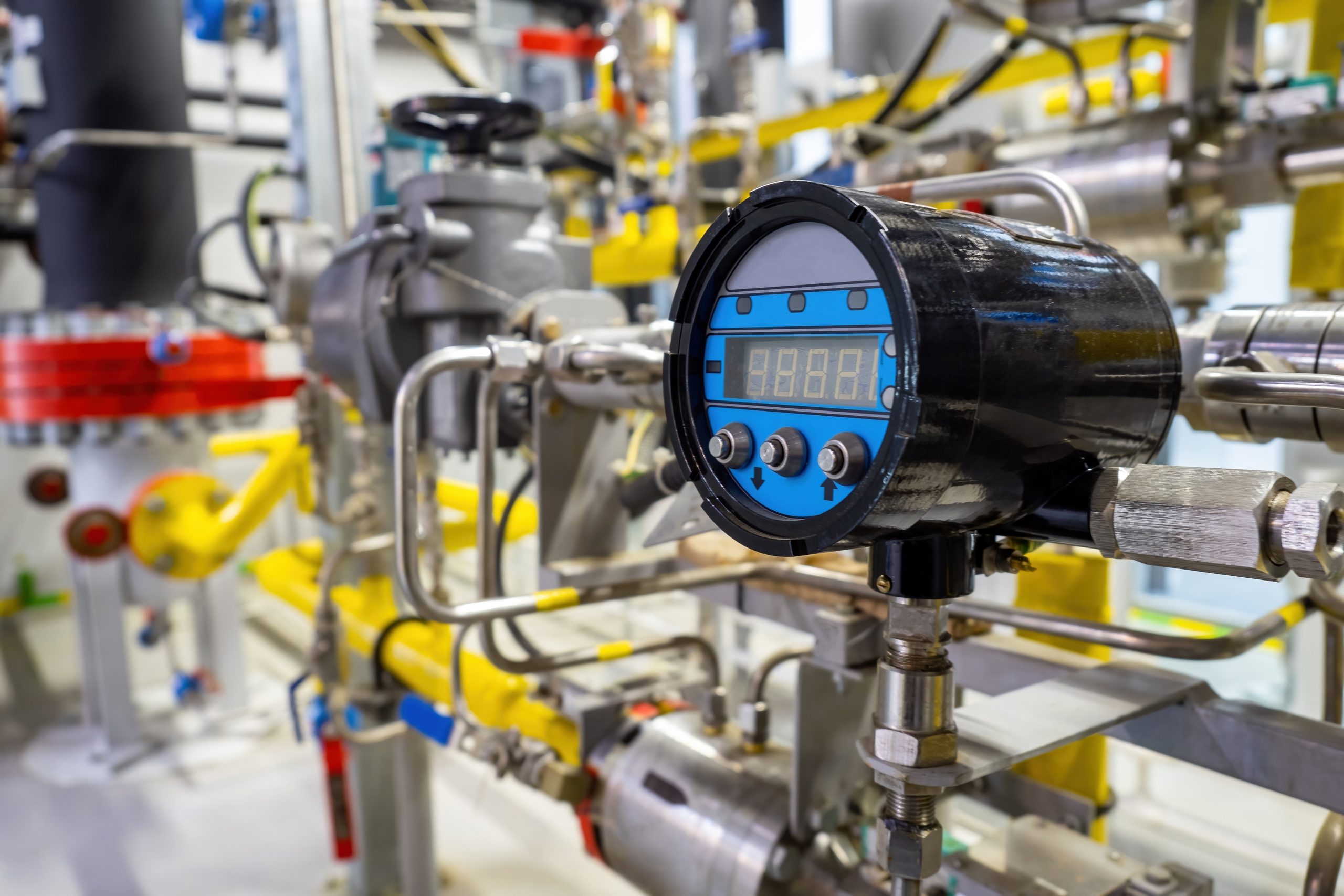
In developing the soft sensor, the first step was to identify – based on Prayon’s expertise – all the process parameters that needed to be selected for inclusion in the model of the system. These process parameters are determined from both in-line sensors (for flow, temperature, pressure and density) and the analysis of samples collected at defined plant locations.
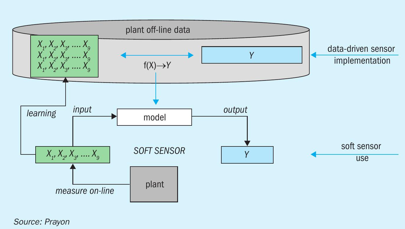
The second step involved acquiring all of the necessary data in a reliable and continuous manner. This step was particularly critical as the analytical modelling results would completely depend on the quality of the input data.
It is no secret that every phosphoric acid plant faces issues such as scaling, corrosion, erosion and plugging – due to the nature of the raw materials and products handled. That makes obtaining reliable in-line data from these plants a challenge. Critical sensors were therefore identified and upgraded to ensure that subsequent data analysis and processing would be successful.
At the same time, data from two sources, laboratory analysis and the distributed control system (DCS), were collected and centralised in a common storage space – called a datalake – and aligned on a common time basis. This collection-centralisation routine was then automated to ensure reliable and continuous analysis of the data.
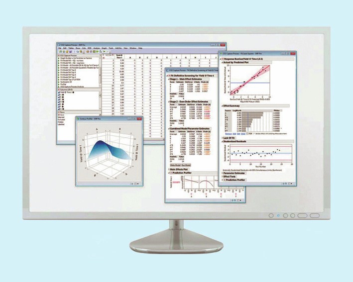
Finally, once this was achieved, data scientists were able to work on the analysis itself, using an algorithm platform that adapts to the type of data collected (Figure 4). Several analytical tools (windowed distribution, decision tree, violin plot, PCA) are used to process the data and to highlight correlations between these.
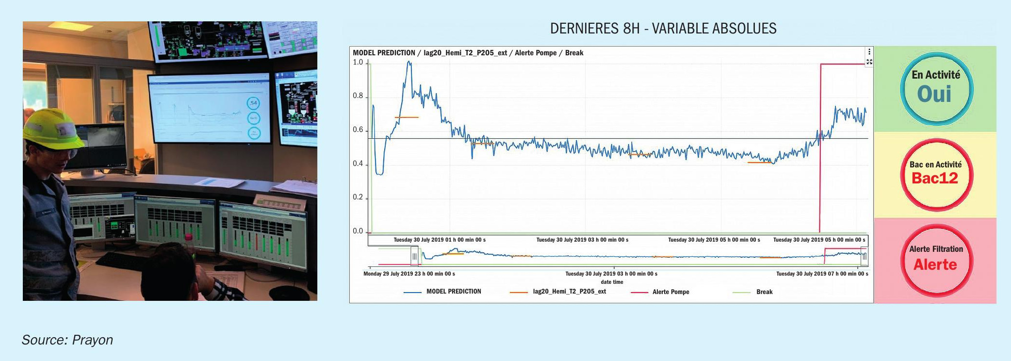
In this way, data analysis enabled a soft sensor to be created. This provides a real-time estimate of the P2 O content in the hemihydrate cake, by combining continuous measurements from real sensor measurements with quick sample analyses (i.e. pump speed, filtrate density). The soft sensor is displayed in the control room of the Engis plant as a dashboard next to the DCS screen (Figure 5).
A success story
Prayon was able to successfully develop a soft sensor for its Engis phosphoric plant. This predicts the P2 O5 content of gypsum cake more quickly than was possible using the previous sampling and laboratory analysis approach. As a result, the plant’s operators are now able to react faster to correct deviations in process performance and, as a consequence, have reduced the quantity of off-spec gypsum (that cannot be sold) by 25 percent. This represents a huge saving for Prayon in terms of gypsum disposal and simultaneously improves valorisation.
Development of the soft sensor firstly required enhancements to the DCS and laboratory data gathering (collection and concatenation) and then the use of data analytics. This concept can be adapted to the specific needs of any phosphoric acid producer.
Based on the experience gained from the successful implementation of a soft sensor at its Engis phosphoric acid plant, Prayon Technologies has decided to offer this service to the industry as part of its long-term collaboration with clients.
FEECO INTERNATIONAL
Tips for optimising phosphate fertilizer granulation
As many plant managers and fertilizer producers know, small inefficiencies – although they may seem inconsequential – can quickly add up, especially when working with the large tonnage throughputs typical of the fertilizer industry.
The production of phosphate fertilizers such as diammonium phosphate (DAP) and monoammonium phosphate (MAP) is certainly no exception.
Fortunately, there are a number of opportunities for plant managers to optimise their process for both maximum efficiency and product quality. These are highlighted here.
Select equipment suited for duty
Process optimisation should start well before the installation of the production line: it actually needs to begin during the equipment design process. From the outset, choosing the right equipment able to meet the demands of phosphate processing is crucial, as selecting inferior and inadequate equipment will inevitably result in frequent shutdowns and repairs.
Phosphate-based materials are hard on equipment. That makes the selection of proper construction materials, the reinforcement of high-wear areas, and appropriate fabrication techniques essential. This not only ensures equipment longevity, but will also avoid frequent process upsets and repairs.
Save energy with a pipe reactor
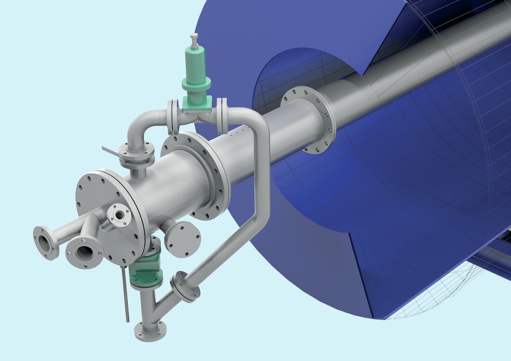
For MAP production, producers should evaluate whether to incorporate a pipe reactor into their granulator (Figure 1). Pipe reactors – although not necessarily an appropriate fit in all settings – do have the potential to recover significant value where installation is appropriate.
Incorporating a pipe reactor into the process enables the beneficial capture of reaction energy. By using this captured heat to dry product in the granulator, significant energy savings can be garnered later on by reducing the burden on the rotary dryer. The tanks previously used for pre-neutralisation can also be repurposed to feed the operation.
Conduct a process audit
When plant managers are confronted by unexplained production inefficiencies, or products of inferior quality are being generated, then calling in the OEM (original equipment manufacturer) or an external consultant to conduct a process audit usually offers the best pathway for expediting matters and resolving these issues.
Process audits – while they can differ depending on the provider and the issue at hand – generally focus on revealing discrepancies between the original design parameters and current operating conditions. Audits can also offer valuable insights into the inner workings of a process and provide benchmark data.
Process audits are not just for troubleshooting headline issues either: they also offer an excellent way of identifying underlying inefficiencies that might not be readily apparent. Plant managers can typically expect one or more of the following benefits from a process audit:
- Reduced energy costs
- Improved product quality
- Increased production
- Minimised downtime
- Better equipment longevity
- Lower maintenance costs
- Greater operator understanding and performance.
Keep equipment maintained
It might sound obvious, but poorly maintained equipment is one of the quickest – and most common – ways that plant inefficiencies and costs can start stacking up.
Poorly maintained equipment cause a host of problems. These include lost product, inflated energy costs, increased wear on equipment and, eventually, premature equipment failure.
Housekeeping is also an important part of maintenance efforts, as fugitive dust and improperly managed materials can degrade equipment and cause mechanical problems.
Maintain a consistent feedstock
Ensuring feedstock consistency is important at every step in the granulation process. As a rule, the more consistent the feedstock entering the equipment is, the more consistent the product that emerges will be.
Look for inefficiencies in the drying step
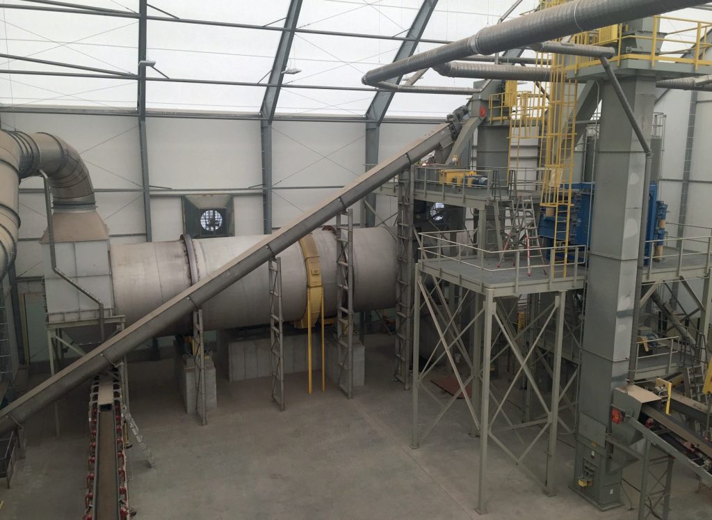
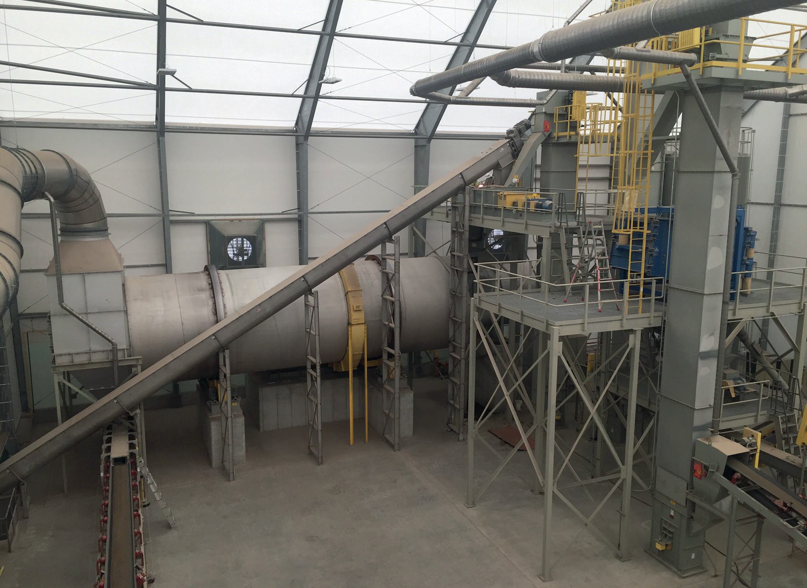
Drying – being the most energy-intensive step in the fertilizer granulation process – also offers the most opportunity for maximising efficiency. Several aspects of the rotary dryer can be assessed and modified to improve efficiency. In examining a dryer, plant managers should:
- Check for air in-leakage: Inadequate dryer seals are a common culprit responsible for inconsistent product quality and high energy costs. Seals should therefore be carefully selected and properly maintained. Sub-par, worn, or damaged seals allow ambient air to leak into the dryer causing a reduction in operating temperature. This, in turn, can reduce capacity, increase fuel costs, and result in inconsistent product quality. Leakage through seals at the discharge end, by adding extra air volume, can also reduce the efficiency of the exhaust gas handling system, potentially causing it to become non-compliant in emissions.
- Assess flight design/pattern: The design and pattern of flights can also have a significant influence on the operating efficiency of rotary dryers, with ramifications for both energy efficiency and product quality. The standardised flight design implemented by many rotary dryer manufacturers will not necessarily match up with the characteristics of individual materials. Consequently, to enable the dryer to function with maximum heat transfer and efficiency, its flight design and pattern should always take the unique characteristics of the material being processed into account.
- Use a combustion chamber: While not every dryer incorporates a combustion chamber, these can offer a number of process improvements to the drying step. Such chambers, by housing the combustion reaction and keeping the flame away from the product, allow producers to maintain product integrity and minimise potential attrition. The use of a combustion chamber also provides more control of the temperature of process gas as it enters the dryer. This allows operators to optimise drying temperature and promotes more uniform heating. Another advantage of combustion chambers is that they provide plant managers with an effective option to utilise recovered waste heat by incorporating it as dilution air. This boosts efficiency by improving fuel combustion and reducing the overall energy demand of the process.
Proper operator training
Ensuring operators receive proper training on the granulation process is vital. A well-trained operator, for example, can often identify potential issues before they escalate, as well as identify and rectify any inefficiencies. Equipment controlled and maintained by properly trained operators will also experience greater longevity.
Minimise build-up
Phosphate-based materials can cause build-up due to their tendency to clump together. Build-up is a concern in any process, as it will result in inefficiencies such as under-dried product, clogged equipment and inaccurate feeding. Build-up is especially problematic during the granulation of phosphate fertilizers because of their corrosive nature. Consequently, the accumulation of materials in crevices and other areas needs to be avoided as it will promote faster and more corrosive wear.
Such build-up can be minimised, whenever possible, through regular equipment cleaning and by employing ‘knockers’ on granulators and rotary dryers to dislodge material. Additionally, the use of belt cleaners at the head and tail pulleys on belt conveyors can reduce undesirable build-up by preventing the migration of material left stuck on the belt onto idlers and other components.
Test changes externally
Producers are under increasing pressure to increase capacity, improve their product, or change their formulation. Particularly as – with specialty fertilizers becoming the norm and fertilizer demand continuing to rise – there is a growing need to develop new formulations and exploit new phosphorus sources. Accommodating these new demands, while continuing to meet existing production schedules, can be a challenge.
Fortunately, producers can take advantage of test facilities such as the FEECO Innovation Center. By simulating commercial-scale conditions, experts at the Center can independently test different formulations and evaluate changes in the production line, without affecting the ‘live’ production environment.
Take advantage of automation
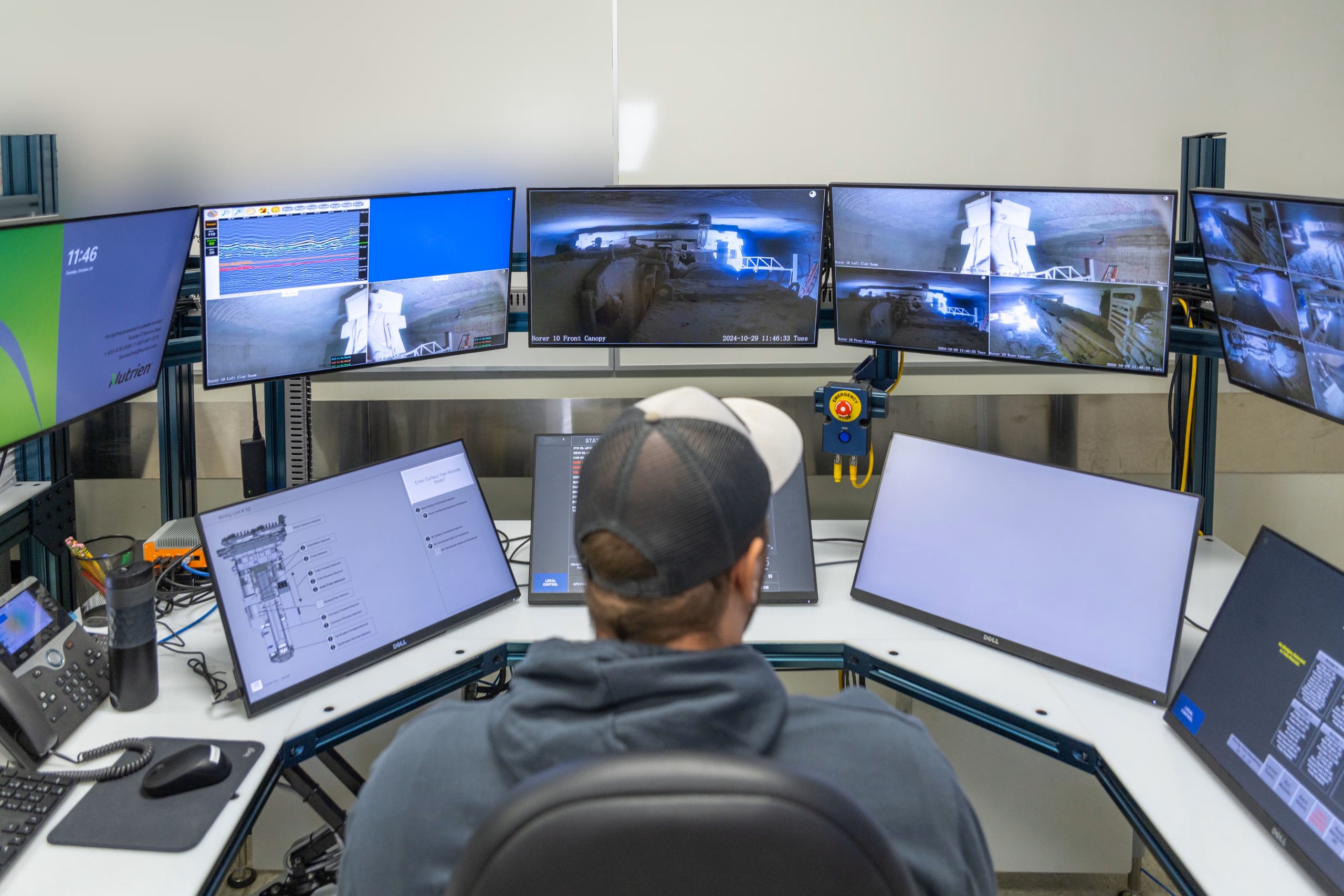
Automation and control systems offer operators tremendous benefits. Although once a luxury, these systems are becoming a necessity, especially as the industrial internet of things (IIoT) starts to become the norm.
As well as being valuable during startup and shutdown, automation and control systems can take day-to-day operations to a new level through data collection, analysis of trends, predictive maintenance, and even proactive alerts. They can also enable operators to monitor process data and plant performance remotely from any location using a tablet or other mobile device.
Systems can even be programmed to alert operators if key parameters start to fall out of specification. This has the advantage of allowing the process to be adjusted before a problem occurs. To provide everyone with the data they need to make decisions, scheduled reports can also be sent out to the appropriate individuals at pre-set intervals.
“In an age where inefficiency has become public enemy number one, a range of options is available to help phosphate fertilizer producers improve their operations.”
Concluding remarks
In an age where inefficiency has become public enemy number one, a range of options is available to help phosphate fertilizer producers improve their operations. Efficiency improvements start by selecting robust equipment designed to withstand the rigours of phosphate production, and end with the advantages and new capabilities offered by automation and control technology. Along the way, producers can optimise their process via a process audit, by keeping equipment properly maintained, and considering the use of a pipe reactor.