Nitrogen+Syngas 375 Jan-Feb 2022

31 January 2022
Scrubbing systems prove their value
SCRUBBING TECHNOLOGY
Scrubbing systems prove their value
Stamicarbon offers advanced scrubbing technologies for fertilizer granulation plants and prilling towers. This article describes the technology and experience with the second operational MMV scrubber, which is installed at the Dakota Gasification Company’s (DGC) urea granulation plant, and highlights the successful pilot test with its JV scrubbing technology.
As countries are moving towards a carbon-free, sustainable future, the fertilizer industry has to contribute to reducing emissions and accelerating the transition to a green economy. Worldwide, emissions regulations and specifically fine particulate emission regulations are becoming increasingly strict. While older scrubbing technology easily collects larger particles, a high degree of sub-micron dust capture required a new approach.
Stamicarbon, the innovation and license company of Maire Tecnimont Group, and EnviroCare International have, in response to this, co-developed the high-efficiency Micro-Mist™ Venturi (MMV) scrubbing technology for granulation plants and the Jet Venturi (JV) scrubber for prilling towers. It removes sub-micron filterable particulate, condensable particulate, and soluble gases at very high efficiencies with low energy input, while reducing liquid effluent waste streams.
Stamicarbon currently has two advanced technology wet scrubbers in operation on the outlet of urea granulation plants and three more MMV scrubbers in the construction and start-up phase. These MMV scrubbers are multi-staged and have a modular box concept design for easy transportation and assembly.
The DGC granulation plant
Stamicarbon and Dakota Gasification Company signed a license agreement for the construction of a brownfield urea melt, granulation, and DEF plant in Beulah, North Dakota, in the United States. This urea plant utilises Stamicarbon’s state-of-the-art LAUNCH MELT™ Pool Reactor technology and the latest optimised LAUNCH FINISH™ Fluid Bed Granulation technology. Both plants have a capacity of 1,000 t/d, each.
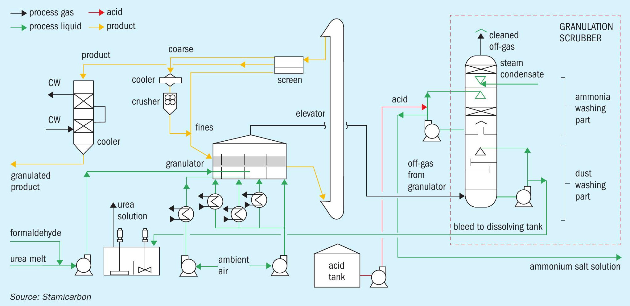
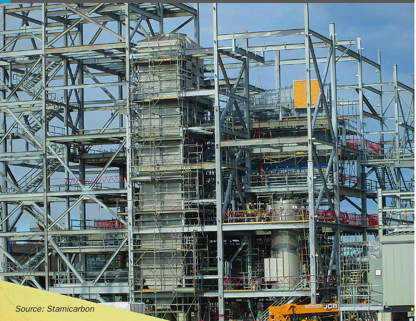
The installed granulation plant (see Fig. 1) is characterised by minimising the number of equipment items, while keeping its original high performance.
Granulation plant output
- The complete solid product flows via gravity through the main screens.
- The coarse product is fed to the crusher after cooling to a temperature of 70°C.
-
The crushed product and the fine recycle flow are combined and recycled back into the granulator as so-called seeds.
-
The on-spec product in the outlet of the main screen is cooled to a storage temperature in a Solex product cooler, which makes use of cooling water instead of cooling air. After the product is cooled down, the final product is directed to the storage.
-
The dust-loaded fluidisation and cooling air from the granulator and all the dedusting points are collected and fed to a single MMV scrubber.
-
The clean air is thereafter exhausted through the off-gas fan into the atmosphere.
To reduce the required amount of fluidisation and cooling air, a water injection system can be provided into the discharge of the fluidisation air fan. This is only operated on exceptionally hot days, to increase the relative humidity and to reduce the total air consumption.
The modular MMV scrubber box concept
The DGC MMV scrubber is designed to produce two separate concentrated blowdown streams: one with concentrated urea solution and the other one with concentrated ammonium sulphate (AS) solution.
The scrubber is fabricated from 316L Stainless Steel plate, and its size is 12 ft x 20 ft x 75 ft (3.7 m x 6.3 m x 22.9 m). It is fabricated in a shop in eight sections that are delivered and assembled onsite. Because each box is 12 ft wide and approximately 9 ft tall, the boxes can be easily shipped on a common carrier to site and be offloaded and stacked. This MMV scrubber system consists of the following equipment: a quench scrubber vessel, a cross over duct, a MMV scrubber vessel, several pump stations, an acid recycle tank, and associated field instrumentation.
MMV process description
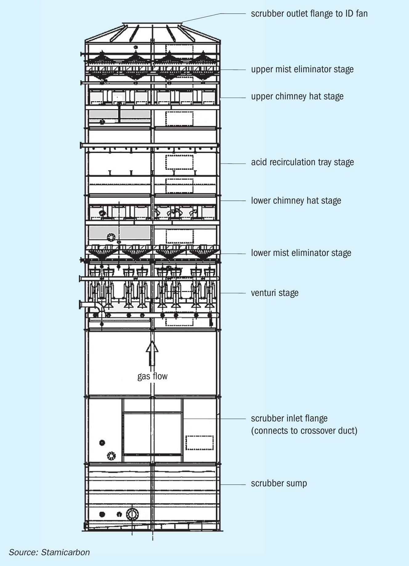
A side view of the DGC box scrubber can be seen in Fig. 2. Exhaust gases exit the urea granulator and flow downwardly into the quench vessel. The quench cools, saturates and removes large particulate from the exhaust gases prior to entering the MMV scrubber vessel. The main components of the MMV scrubber vessel include the venturi stage, lower mist eliminator stage, lower chimney hat stage, acid recirculation impingement tray stage, upper chimney hat stage and upper mist eliminator stage. The venturi stage utilises finely atomised water droplets combined with high differential velocity to scrub gas-entrained aerosols and fine particulate from the gas stream not captured in the preceding stages. Two mist eliminator stages remove remaining water droplets from the gas stream. Two chimney hat stages inhibit scrubber water injected in upper stages from draining into lower stages. The acid recirculation impingement tray stage captures water-soluble volatile compounds. The treated gas stream then proceeds through the ID fan to the stack. Due to the placement of the ID fan, the pressure inside the scrubber is below atmospheric pressure.
During the crystallisation process of urea melt in a granulator, urea dust is generated and some ammonia present in the urea melt is released and both components are emitted into the air. At the DGC plant both components (urea dust and NH3 ) were collected simultaneously in a single MMV vessel.
The majority of the urea dust is collected and separated from the air flow in the quench. The urea scrubbing solution is partly re-circulated as scrubbing solution to the quench and partly pumped to urea dissolving vessel. The remaining sub-micron urea dust is additionally collected at the multi venturi stage section and this dilute urea solution is also send to the quench (make up) and the dissolving vessel, and finally recycled back into the melt plant.
Downstream of the MMV stage, ammonia abatement takes place. To efficiently capture ammonia, it is required to apply acidic scrubbing with sulphuric acid. The ammonium sulphate (AS) solution generated after the reaction between the ammonia present in the off gas and the sulphuric acid scrubbing is concentrated by circulation, stored in the AS tank, and finally sent to OSBL. Because of this single MMV scrubber set-up it is important to keep both liquid streams (urea- and AS solution) separated.
The MMV operation
The quench vessel, installed downstream of the urea granulator (see Fig. 3), is designed to remove large particulate while saturating the incoming process gases.
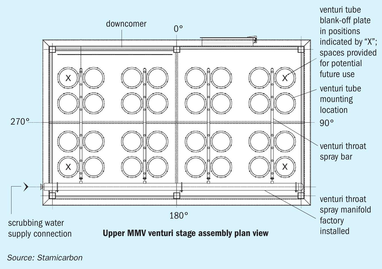
The first stage that the granulator exhaust gasses encounter as they exit the cross over duct and enter the MMV scrubber vessel is the venturi stage section. The primary function of the venturi stage is to capture any residual fine, sub-micron particulate including condensable constituents and aerosols that have carried over from the quench stage. The venturi stage consists of a solid diaphragm with mounting locations for 32 venturi tube assemblies (28 venturi tubes initially installed at DGC, see Fig. 4), eight factory installed venturi inlet spray bars, and four venturi throat spray bars. Venturi tubes, mounted in parallel, produce extremely high particulate collection efficiencies by creating of an elevated relative velocity differential between the water (being injected by sprays) and particulate laden gas stream. The exit of the venturi tube is designed to recover the velocity pressure, minimising the fan energy requirement for the system.
Each venturi tube assembly consists of a mounting plate, inlet cone, throat, low energy loss outlet diffusion cone assembly, throat spray nozzle connection, and outlet deflector plate. Factory installed venturi throat spray bars distribute water via flex hoses to the throat spray water feed connections on each of the venturi tubes. Throat spray supply water is modulated via the throat spray pump, which is variable frequency driven (VFD), to control pressure drop across the venturi stage for differing operating conditions. As gas flow decreases, the corresponding pressure drop across the venturi stage falls unless more water is added. To maintain the venturi stage differential pressure when gas flow decreases, the VFD increases the throat spray water flow, which also maintains the high scrubbing efficiency. Each throat spray is centred in the venturi tube throat to spray counter to the gas flow.
A chevron mist eliminator (ME) array is installed above the venturi stage. The equipment installed in this stage functions to keep the water in the venturi stage and minimise carryover to the downstream stages. The ME irrigator sprays continually rinse the bottom (upstream) side of the chevrons to reduce the possibility of urea build-up on the ME.
The lower chimney hat stage is installed above the lower ME stage. The chimney hat stage prevents recirculated acidic solution in the upper stages from draining into the recirculated venturi dilute urea solution in the lower stages.
The acidic recirculation tray stage is installed above the lower chimney hat stage. This stage consists of two levels of dual orifice impingement trays. Scrubbing water dosed with sulphuric acid is continually recirculated over the top of the trays via the ammonium sulphate (AS) solution vessel. Process gasses are forced to pass through recirculated AS solution via small perforations in the trays. Gas phase ammonia, not captured in the previous stages is scrubbed in this stage and converted to AS using the sulphuric acid solution. The AS solution is concentrated and bled off to storage where it is collected for resale value by an AS crystallisation unit.
The upper chimney hat stage is installed above the acid recirculation tray stage. The equipment installed on this stage prevents AS droplets to enter the next stage and a small portion of the recirculated demister water (ME spray water) in the upper stages from draining into the recirculated AS solution in the lower stage.
An upper chevron mist eliminator (ME) array is installed above the upper chimney hat stage. The equipment installed in this stage functions to keep water from the acid recycle scrubbing stage entrained in the gas stream from carrying over to the ID fan and stack. The ME irrigator sprays rinse the bottom (upstream) side of the chevrons to reduce the possibility of build-up. An on/off block valve, mounted in the field piping upstream of the sprays allows for them to be sprayed as required. The chevrons are intermittently backwashed from above via the ME backwash spray bars. Washing of the mist eliminator prevents particle build up by ensuring proper drainage of captured particulate laden droplets under all operating conditions. The backwash nozzles provide intermittent cleaning using large droplets that do not carry over to the stack.
The MicroMist scrubber system utilises six pump stations to circulate the various scrubber water sources, providing the corresponding design nozzle injection pressures. All six of the pump stations are similar in design. Each station consists of two water pumps although only one pump is required to operate to provide design pressure and flow to the corresponding spray nozzles.
The remaining pump is a standby pump. The pumps are installed in parallel with common inlet and discharge piping. Each pump train consists of an inlet simplex strainer, discharge check valve and pressure gauge, and inlet/outlet isolation valves to facilitate equipment maintenance.
Test results
After the plant was successfully commissioned and the scrubber had been running stable for several weeks, the official stack test was performed. DGC hired an independent company to conduct particulate matter emission compliance test program on the urea granulation stack. This test programme was completed in accordance with the North Dakota Department of Health, Air Quality Division. Emission testing was conducted following the methods specified in 40 CFR, Part 60, Appendix A; and 40CFR51, Appendix M.
The performed stack test measurements were: filterable particulate matter (FPM), condensable particulate matter (CPM), total particulate matter (TPM), and opacity. FPM was measured using EPA Method 5. CPM was measured using EPA Method 202. TPM is simply the addition of CPM and FPM. The opacity was measured using EPA Method 9.
The purpose of the emission testing programme was to demonstrate the particulate matter emission rates during the normal operating condition. The achieved results of the test program, without any additional fine tuning of the scrubber showed that the total particulate matter was <10 mg/Nm3 and visible emissions were determined in accordance with EPA Method 9. The opacity measured by using EPA Method 9 was zero (0%).
In-operation observations
Throughout the first year of operation, the DGC plant employees steadily improved and optimised the equipment tuning, resulting in smoother operating conditions with no upsets. At times, the unit produced above the original capacity factor, reaching 115% production capacity factor briefly, and 105% for a sustained period.
Although from routine lab tests, DGC noticed more than expected AS values measured in the quench urea water. The ammonium sulphate solution data is the sulphuric acid and ammonium sulphate solution circulating in the middle/top part of the MMV scrubber (ammonia abatement) and the quench urea water data is the solution in the quench scrubber upstream of the MMV. Quench loop sulphates values have remained minimal but constant and did not lead to any product quality issues.
The most logical explanation why AS can appear in the quench loop is that some AS solution was leaking through the chimney hat and flowing upstream to the lower MMV stages. Stamicarbon and EnviroCare were comfortable with the designed chimney hat stage, but there were some flow dynamics that caused splashing to allow AS solution to migrate downward through the chimney hat openings and into the upstream stages.
After some tests, it was decided to modify the lower chimney hat diaphragm during the first scheduled maintenance for the DGC plant between 5 October 2019 and 10 November 2019. During this shutdown the lower chimney hats in the MMV scrubber were modified to prohibit splashing, and 4 additional venturi tubes were installed to lower the venturi stage pressure drop.
During this scheduled shutdown, DGC thoroughly inspected the quench and MMV scrubber internals for anything out of the ordinary, like shifted or displaced equipment (mist eliminator sections, DOI trays, venturi tubes). The spray nozzle plumes were confirmed to be uniform and all spray nozzles each specific area or stage operated similarly. The nozzle bodies were visually checked for excessive wear that could compromise function. All flex hoses, gaskets and nozzles appeared to be in good condition, and none needed to be replaced.
As mentioned earlier, four additional venturi tubes were added (to 32 in total) to provide a larger operating range for the venturi throat spray pumps. With the addition of four additional venturi tubes, the plant has much better control since the throat pump is operating mid-range instead of at the bottom of its range and still meeting their earlier achieved emission guarantees (same pressure drop setting).
After the shutdown, there was a significant decrease in AS concentration (from 0.28% to 0.002%) in the quench urea solution after the chimney hat was modified.
Jet Venturi scrubber for prilling towers
The exhaust gas from a prilling tower has a very fine dust, with an extremely large surface area and with the share of sub-micron particles ranging up to 70 wt-% of the total dust load. Such a fine dust creates a highly visible, persistent plume that doesn’t dissipates easily. Because of this, environmental regulations for prilling tower emissions are becoming stricter. Allowed emission levels are currently maximum 50 mg/Nm3 for dust within Europe. The limits are even more stringent in some other regions. In that regard, Stamicarbon and EnviroCare International have been working on developing a Jet Venturi (JV) Scrubber for prilling towers with a significant high content of sub-micron particles. This scrubbing technology makes it possible to reach very low emission levels.
JV scrubber design
The technology is suitable for both natural and forced draft prilling towers. The scrubbing unit can be placed on the ground (at grade level) or on top of the prilling tower. The latter is preferred since less ducting is required, which has benefits in terms of capex and leads to no additional pressure drop.
Moreover, by utilising their jet effect, the applied venturis move the off gas through the dust scrubber themselves. The result is that operation of a Jet Venturi scrubber itself does not require any additional fan capacity.
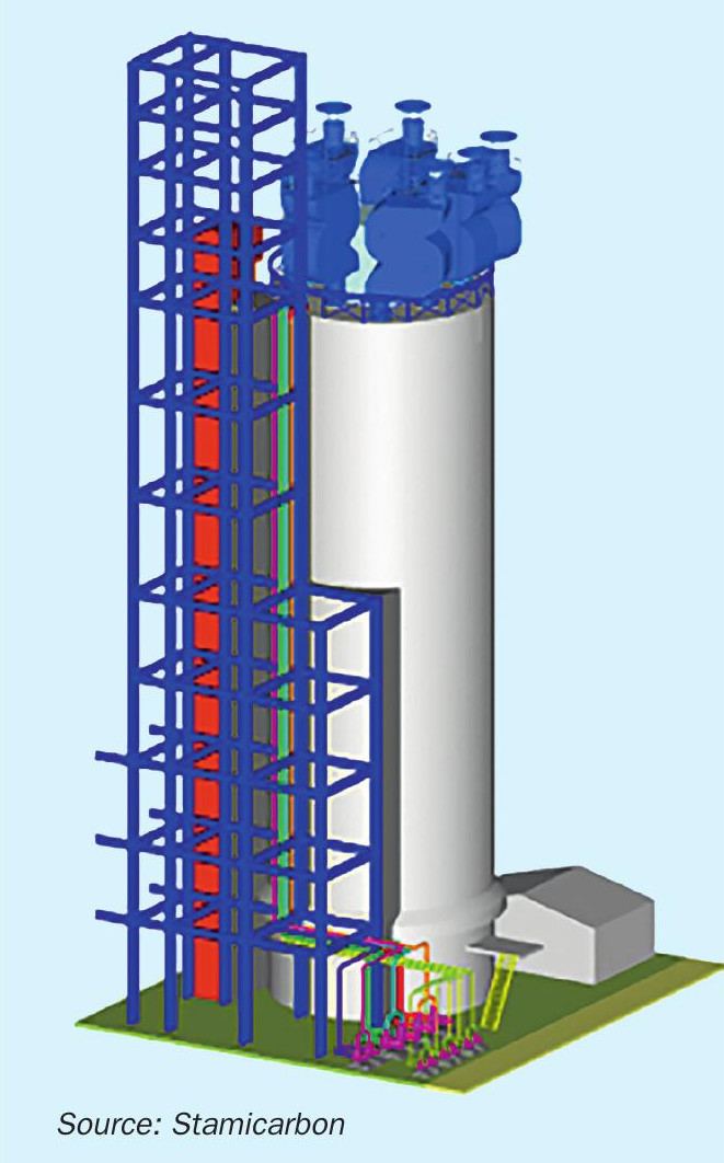
For a forced draft prilling tower, the JV scrubbing units are preferably mounted directly on the air exhaust stacks, with each stack having a dedicated scrubbing unit (Fig. 5). The scrubbing units comprise a few compact stages that progressively treat and clean the off gas from dust and ammonia contamination:
- quench scrubbing stage in which coarse urea particulate is removed from the gas stream by spraying recirculating urea solution;
- primary JV stage with multiple venturi elements installed in parallel for removing fine particulate by recirculating concentrated urea solution;
- secondary JV scrubbing stage with multiple venturi elements installed in parallel for removing remaining fine particulate by recirculating diluted urea solution;
- optional acidic scrubbing stage to reduce the ammonia emission.
“Jet Venturi scrubber plant owners can rest assured that the most stringent environmental regulations are being met.”
Pilot
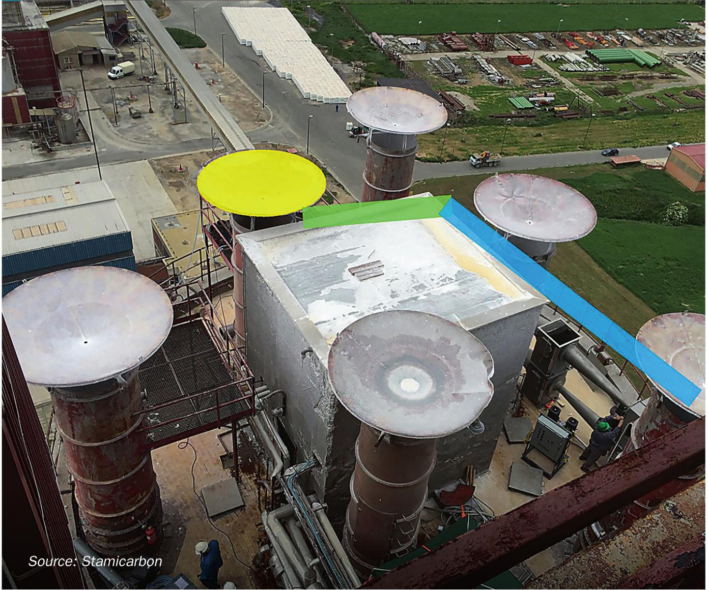
A pilot unit was set up in cooperation with a Stamicarbon client. The idea was to prove the concept by using a single Jet Venturi lay-out, thus to have two Jet Venturi elements in series representing primary and secondary scrubbing stages.
The treated gas was extracted from one of the prilling tower stacks (highlighted in yellow in Fig. 6) and via connecting pipe (highlighted in green) fed to the pilot unit (highlighted in blue).
Conducted tests demonstrated that the expected dust emission from the prilling tower with implemented Jet Venturi scrubber is less than 15 mg/Nm3 , way below the current European emission limit of 50 mg/Nm3 . This technology is also suitable in combination with debottlenecking of existing prilling towers.
Conclusions
The operational results and the small modifications to the DGC scrubber installation have been included into the latest MMV scrubber design. The final emission performance of the MMV scrubber for dust of less than 10 mg/Nm3 (dry basis) and an opacity of zero percent prove that this technology is very efficient and valuable for a granulation plant meeting the given air permit or environmental regulations.
Based on the real-plant experience with the MicroMist™ Venturi scrubber and the on-site tests conducted with the Jet Venturi scrubber plant owners can rest assured that the most stringent environmental regulations are being met, while decreasing its investment cost.