Sulphur 399 Mar-Apr 2022

31 March 2022
Pathway to an emission-free fertilizer complex
EMISSIONS REDUCTION
Pathway to an emission-free fertilizer complex
With climate change looming there is an increased focus on reducing the environmental footprint of the production of fertilizers. The use of renewable energy/green hydrogen is one way to make the fertilizer industry more environmentally sustainable. In this article, Rene Dijkstra of Chemetics introduces the Green Fertilizer Complex. This practical solution integrates an oxygen-based sulphuric acid plant using the Chemetics’ patented CORE-SO2™ process with a green hydrogen and ammonia facility to deliver low cost, low emission, and carbon-free phosphate (MAP/DAP) and/or sulphate (AMS) based ammonia fertilizers.
Large scale production of fertilizers containing phosphate and nitrogen is imperative to be able to produce sufficient food for the world’s population. As a result, the fertilizer industry has become a significant contributor to worldwide CO2 emissions especially if the process involves the use of ammonia in the production chain. As ammonia is not only used in fertilizer but is also increasingly seen as a potential energy carrier, it is to be expected that worldwide production of ammonia will continue to increase. As a result, there will be increasing pressure to replace the steam methane reforming process to produce ammonia due to its large CO2 emissions.
The Chemetics CORE-SO2™ process offers a cost-effective method to produce sulphuric acid from sulphur with extremely low emissions while taking full advantage of by-products from other process units in the fertilizer complex and is particularly well suited for integration with a green ammonia facility.
The CORE-SO2™ process
The CORE-SO2™ process produces sulphuric acid from molten sulphur and pure oxygen utilising the proprietary Chemetics CORE™ reactor. The use of pure oxygen reduces the size, complexity, and the cost of sulphuric acid production as the CORE reactor can operate at SO2 concentrations up to ~60 vol-%. As a result, the gas flow through the CORE-SO2 plant is reduced by more than 70% compared to the gas flow in a conventional sulphur burning acid plant using DCDA technology operating at 11.5 vol-% SO2 to the converter. Advantages in capex are obvious, but the reduction in equipment size and count also allows much larger sulphuric acid plants to be designed, especially for plants supplied in modules which have inherent lower site erection time and cost.
The CORE-SO2 process consists of four main sections:
- SO2 generation;
- SO2 conversion system;
- absorption system;
- purge gas system.
SO2 generation system
The first generation of the CORE-SO2 plant introduced at the 2018 Sulphur Conference utilised a submerged combustion system to ensure low temperatures in the SO2 generator. Even though submerged combustion systems for sulphur have been in operation since 1989 to generate concentrated SO2 gas, Chemetics discovered that it was not required to achieve its goals. Therefore, the CORE-SO2 process was further optimised, resulting in a reduction in the equipment count and a simplification of the overall design.
The new SO2 generation system was developed to provide a familiar, yet highly efficient, combustion of sulphur and oxygen. The process is carried out using a standard combustion chamber with an integrated gas recycle. The easy to operate recycle system allows control of the combustion chamber temperature independently from the SO2 concentration. Controlling this temperature is important to prevent refractory brick damage and the formation of nitrogen oxides which can form at high temperature from trace nitrogen contained in the oxygen feed. The gas from the SO2 generator is cooled in a boiler/superheater combination before it enters the conversion system (see Fig. 1).
The SO2 generator design is highly flexible, easy to control and allows a gas stream with any SO2 concentration to be generated. Depending on the oxygen source, the SO2 concentration leaving the SO2 generation system will be controlled between 40 to 60 vol-%.
SO2 conversion system
In the conversion system the SO2 is further oxidised to SO3 using a CORE-S™ reactor. The CORE-S reactor is a tubular reactor where the catalyst is located inside the tubes and a liquid coolant outside the tube (see Fig. 2). With this arrangement the gas is cooled as the heat of reaction for the SO2 oxidation is released, allowing the reactor to operate with very high SO2 concentrations compared to the traditional adiabatic converters used in the DCDA process. The CORE-S reactor is designed to process gas with up to 60 vol-% SO2 . This process gas enters the CORE-S system where most of the SO2 is converted to SO3 . The coolant maintains the process gas temperature below 630°C to prevent catalyst damage. A specially developed catalyst mixture with high heat transfer capability is used to prevent hot spots in the centre of the catalyst. In the reactor more than 90% of the reaction energy is transferred to the coolant.
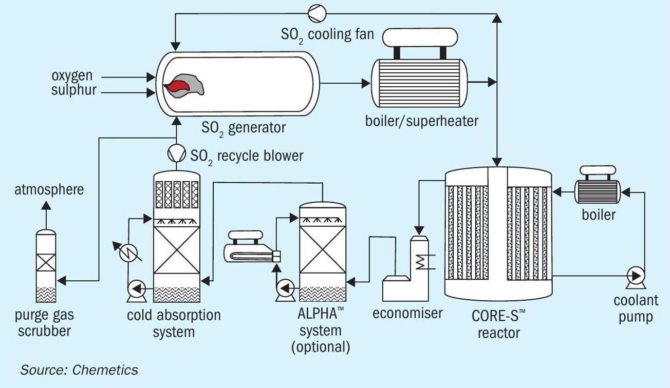
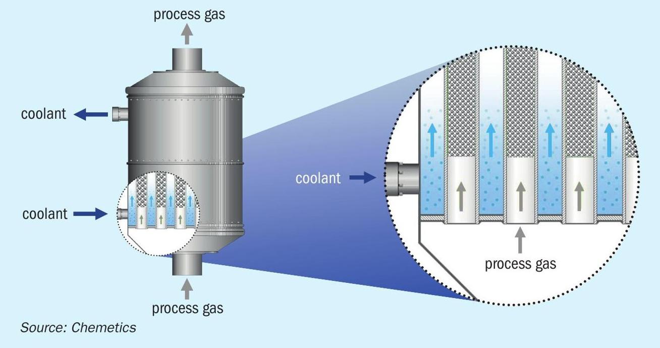
The cooling system maintains the optimum temperature to keep the catalyst active. It therefore operates at moderate temperatures, close to the catalyst activation temperature, and hence no special materials of construction are required in the CORE-S reactor system. The coolant temperature is controlled using a boiler producing saturated high-pressure steam. This configuration provides precise control of the temperature in the CORE-S reactor independently from other parts of the process. During start-up and periods when the plant is not operating the coolant temperature is maintained with a small electric heater and a hydrocarbon fired preheat system is not required.
After leaving the CORE-S reactor the process gas is cooled using an economiser. The cooled gas from the economiser flows to the absorption system where the SO3 is converted to sulphuric acid.
Because of the compact design with small gas volumes more energy can be recovered. As a result, up to 10% more steam can be produced, depending on the selected steam pressure and temperature. Typical high-pressure steam export conditions are 60 bar(g) and 500°C, but these can be fully adjusted to meet client requirements. In most cases the HP steam is optimised for power generation in a turbine-generator.
Absorption system
The SO3 formed in the CORE-S reactor is absorbed in the absorption system. This can be a conventional low temperature (cold) absorption system or a more energy efficient CES-ALPHA™ System to utilise the hot concentrated acid to produce medium pressure steam. Due to the much higher inlet SO3 concentration in the CORE-SO2 process a higher percentage (>99%) of the SO3 can be absorbed in the ALPHA tower resulting in more steam production than is possible for a conventional DCDA plant. Because the incoming oxygen contains no moisture (in contrast to ambient air) this MP steam production level can be maintained regardless of the plant location and the MP steam production is not reduced during times of increased humidity as experienced in a conventional acid plant using ambient air in many locations.
As a lower cost alternative to the MP steam generation, hot water can be provided which can be used to produce desalinated water or as heating medium in the complex. Producing a combination of steam and hot water is possible, allowing use of this valuable (green) energy to be tailored to the requirements of the fertilizer complex.
Most of the process gas leaving the absorption system is recycled to the SO2 generation system using a small blower. This provides full utilisation and conversion of the SO2 and O2 .
The acid from the absorption system is passed through a product stripper to remove dissolved SO2 from the acid. The product stripper utilises a small flow of oxygen as the stripping medium. When the oxygen is received from an electrolysis unit, this product stripper is used to dry all the incoming oxygen before it is used preventing corrosion in the plant.
Plant emissions
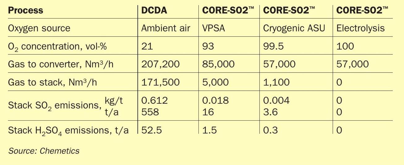
The CORE-SO2 process results in very low emissions as only inert gases contained in the oxygen source need to be removed from the gas circulation. The significant impact this has on the stack volume and emissions is illustrated in Table 1. As can be seen, a CORE-SO2 plant operating with cryogenic oxygen can achieve an impressive 99% reduction in total annual stack emissions.
It is further important to note that a CORE-SO2 plant using only oxygen from an electrolysis system produces no effluents during normal operation and a stack with associated environmental permits may not be required.
Plants using oxygen from other sources require a purge stream from the recycle blower to remove inert gases (mainly nitrogen and argon) from the system which prevents accumulation. This purge flow is treated in the purge gas scrubber. Typically, depending on the plant size and location, a simple scrubber is sufficient. This fully integrated scrubber offers low operating cost and is designed to generate no effluent.
Sulphuric acid mist emissions are directly related to stack gas volume and as shown in Table 1, due to the low stack gas flow in the CORE-SO2 process become almost insignificantly small.
Oxygen supply
The CORE-SO2 will require a supply of high purity oxygen in an amount equal to almost 50% of the acid plant capacity. Thus, a 2,500 t/d sulphuric acid plant requires a 1,230 t/d oxygen supply source. Site locations with no existing oxygen supply will require a new dedicated or shared oxygen plant. There are two common options to supply the oxygen:
For smaller capacities a vacuum/pressure swing absorption (VPSA) system is the most cost effective. VPSA plants utilise adsorbent beds to separate the oxygen from the ambient air and produce an oxygen stream with a concentration up to ~93 vol-%. Capacities of individual units are limited to approximately 250 t/d oxygen, but the use of multiple units is not unusual to deliver higher capacities.
For oxygen capacities larger than approximately 500 t/d, cryogenic air separation units (ASU) are more cost effective and single train cryogenic units with more than 2,500 t/d oxygen capacity are currently operating. In the cryogenic ASU the oxygen is separated from the nitrogen using distillation at very low temperature where they are in the liquid state. The oxygen purity from the ASU is much higher than can be achieved in a VPSA systems with standard purity oxygen production defined as 99.5 vol-% or better. As previously shown in Table 1, this higher oxygen purity further reduces the stack emissions from the CORE-SO2 Process compared with VPSA oxygen.
An additional benefit of the cryogenic air separation is that it allows high purity nitrogen to be co-produced at virtually no additional cost. This is very useful in a fertilizer complex where ammonia is also produced as the ASU can produce both the nitrogen for the ammonia plant and the oxygen for the sulphuric acid plant. The ratio of nitrogen to oxygen produced can be selected at the design stage to match the ammonia and sulphuric acid production capacities required.
The integrated fertilizer complex
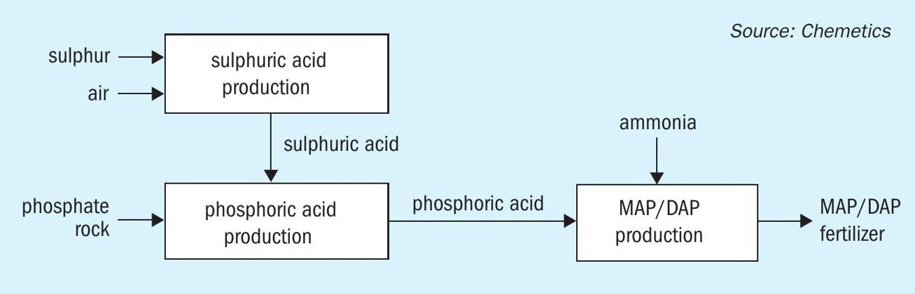
A simplified fertilizer complex for production of MAP/DAP fertilizer is shown in Fig. 3. Sulphur and ambient air are used to produce sulphuric acid, which in turn is reacted with phosphate rock to produce phosphoric acid. The phosphoric acid then reacts with ammonia to produce the MAP/DAP (or NPK/TSP) products. Energy released in the production of sulphuric acid is recovered as HP steam and used to produce power. This power is used to operate the other units in the complex and in most cases excess power is available which can be sold. To avoid CO2 emissions in the MAP/DAP granulation plant it will be necessary to install indirect drying of the product (e.g., steam drying) rather than the direct fired dryers that are currently more commonly used.
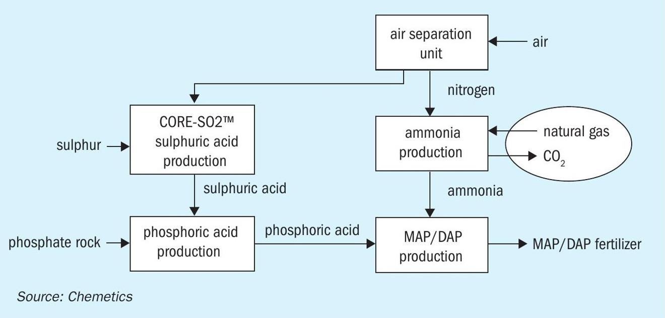
When ammonia production is added to the complex then further integration is possible. Ammonia is produced using the Haber-Bosch process from a mixture of nitrogen and hydrogen. The hydrogen is typically produced from natural gas using a steam methane reformer (SMR). Depending on the SMR design, nitrogen is either supplied by adding air into the reformer or by supplying it from an air separation unit. The latter process has the advantage that the amount of process gas leaving the SMR, which must be purified before the ammonia loop, is significantly reduced, and further allows other hydrogen sources to be easily incorporated.
The process using an ASU is depicted in Fig. 4. It is obvious that this line-up has additional benefits as the by-product oxygen from the ASU can now be used in a CORE-SO2 sulphuric acid plant.
Sufficient power can be produced from the energy released in the sulphuric acid and ammonia production units for the entire complex and no electrical power import is required. It is however obvious that the conventional ammonia process is a significant producer of CO2 due to the hydrocarbon feedstock.
Green fertilizer complex
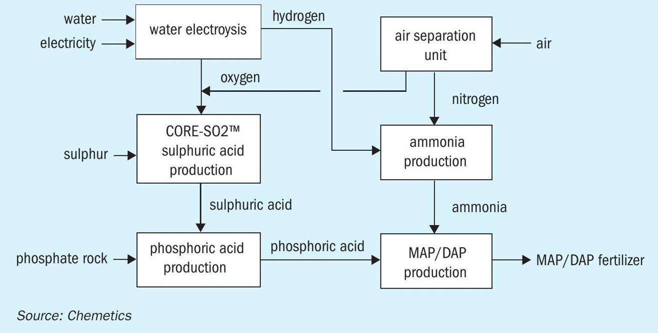
To make the fertilizer complex carbon free it is necessary to eliminate the CO2 emissions from the production of ammonia and hence a different source of hydrogen is required. This carbon-free hydrogen is often referred to as green hydrogen when the hydrogen is produced by electrolysis of water using renewable energy. Several options exist to produce green hydrogen. Both PEM and alkaline water electrolysis are already in use at industrial scale, and solid oxide electrolysis operating at higher temperature also holds promise for the future. In all cases, water is split into hydrogen and oxygen. The hydrogen is used for the ammonia production, but just as with the ASU unit, the by-product oxygen can now also be used to produce sulphuric acid. This additional oxygen source can either be used to produce more sulphuric acid or it can be used to reduce the size of the ASU. This process is shown in Fig. 5.
At the heart of this fully integrated complex is the CORE-SO2 Process to produce sulphuric acid from sulphur and pure oxygen. It not only takes full advantage of the ‘free’ by-product oxygen, but it also provides the power to run all unit operations except the electrolysis.
For locations with limited fresh water supply, excess energy from the CORE-SO2 plant can also be used to produce high quality desalinated sea water or brackish water for use in the electrolysis unit and steam boilers. The fully integrated process, now only using air, water, sulphur, and phosphate rock as raw materials produces fertilizer without any CO2 or SO2 emissions.
Noteworthy is that the integrated fertilizer complex as shown in Fig. 4 could be incrementally switched over to green hydrogen without any changes required for the other process units. This allows on-site green hydrogen capacity to gradually replace carbon-based hydrogen production as additional renewable energy sources become available. As a further benefit, when green hydrogen production is increased, the sulphur emissions from the sulphuric acid plant are reduced as less inert gases enter the process with the oxygen from the ASU.
Energy integration
The integration of the complex is not complete without optimising the energy integration. Both the sulphuric acid and ammonia processes produce excess energy. Most of this energy can be captured from high-temperature sources and is used to produce superheated high-pressure steam. For a complex producing only DAP this combined steam production at 60 bar(g) and 500°C works out to approximately 1.40 to 1.45 kg steam/kg sulphuric acid.
Low-pressure steam (at 5-7 bar(g)) is required for the deaerators, sulphur melting, phosphoric acid evaporators and the MAP/DAP granulation plants. This steam is generally provided using a combination of extraction from the turbine-generator and the steam generated in the ALPHA™ system in the sulphuric acid plant.
An important factor in the amount of LP steam required is the process selection for the phosphoric acid plant. The di-hydrate (DH), hemi-hydrate (HH), hemi-dihydrate (HDH) and others produce phosphoric acid from the main reactor at different concentrations ranging from 28% to 44%. Higher phosphoric acid concentrations require far less steam to reach the final merchant grade acid concentration in the subsequent phosphoric acid evaporators. With less LP steam required in the phosphoric acid evaporators, less or no steam will need to be extracted from the steam turbine and more electrical power can be generated. This will allow the complex to provide some stabilising baseload power to the water electrolysis.
Further opportunities for energy integration can be found by recovering and using low grade heat in the various units (e.g. using a hot water network). These are outside the scope of this article but should be reviewed early in any new project.
Conclusion
The Chemetics CORE-SO2 process sets new benchmarks for sulphur emissions, allowing a step change in reducing sulphur dioxide and sulphuric acid mist emissions compared to the traditional DCDA process. At the same time, it provides compelling economics with lower capex and opex. When integrated into a fertilizer complex these economics are further improved when taking advantage of ‘free’ by-product oxygen available from other units. Fully integrated with a green ammonia plant, the CORE-SO2™ process enables the production of low cost, CO2 , and sulphur emission-free fertilizer.