Nitrogen+Syngas 381 Jan-Feb 2023
31 January 2023
Advanced Methanol Amsterdam
GREEN METHANOL
Advanced Methanol Amsterdam
Advanced Methanol Amsterdam (AMA) is a production facility, that will be realised in the Port of Amsterdam’s Biopark, which is destined to produce advanced methanol that meets the European renewable energy directive (RED) requirements. Once completed, AMA will be the flagship production site for GIDynamics and GIDARA Energy and for its High Temperature Winkler (HTW ® ) gasification technology. AMA will also be the first of its kind green methanol unit designed by Casale.
Casale has been active for several years in the development and optimisation of sustainable technologies to be applied in the production of both ammonia and methanol, which are two of the most energy intensive chemical products, responsible for the emission of large quantities of CO 2 .
There are essentially two routes to reduce the carbon footprint: the first is to capture and sequestrate the CO 2 after its generation, resulting in so-called “blue” products; the second is to totally avoid the CO 2 generation and emissions by the use of renewable energy and feedstocks which results in “green” products.
These routes have led to the development of Casale Flexiblue and Flexigreen baskets which include schemes for the eco-friendly production of ammonia, hydrogen and methanol.
Although the biomass gasification route leads to a plant which is similar to a coal gasification plant, of which Casale has almost 20 references in China, the Flexigreen methanol scheme has been developed to meet to the challenges of the renewable methanol market.
“Green” methanol can be produced using renewable energy and renewable feedstocks via two routes:
- Bio-methanol is produced from sustainable biomass which includes forestry and agricultural waste and byproducts, biogas from landfill, sewage, municipal solid waste (MSW) and black liquor from the pulp and paper industry.
- E-methanol is obtained by using CO 2 captured from flue gases or direct air capture and green hydrogen, i.e., hydrogen produced with renewable electricity.
Methanol is a key product in chemical industry: it is one of the four bulk chemicals (alongside ethylene, propylene and ammonia) used for producing all other chemical products and it is used as fuel (either by itself or as a blend with gasoline, or for the production of biodiesel, or in the form of MTBE as well as DME).
Nowadays, more than 99% of methanol is produced from fossil fuels and its production is responsible for 10% of the CO 2 emissions from the whole of the chemical and petrochemical industries.
Based on current forecasts, the production of methanol will increase by 20% by 2025/2030. It is in this scenario, with these environmental constraints, that the green methanol market will become increasingly popular.
The production of renewable methanol is being boosted by the recent COP26 inputs to mitigate climate change by substantially reducing or eliminating CO 2 emiss ions: green methanol could be a key item in decarbonisation strategy, particularly as a feedstock in the chemical industry or as a fuel in road or marine transport.
The main obstacle to green methanol uptake is its higher cost compared to fossil fuel-based production, and that cost differential will persist in the recent future. The implementation of several policy interventions could reduce costs mainly addressing process differences and facilitating the scale-up of production and use. With the right support mechanisms, and with the best production conditions, renewable methanol could approach the current cost and price of methanol from fossil fuels.
Currently, in the Netherlands, around 20% of the waste is not recycled. The HTW gasification technology has been modified and employed to utilise this waste to produce syngas and thereafter biomethanol with the use of Casale’s Flexigreen methanol scheme.
GIDARA Energy B.V. is focused on converting non-recyclable waste into advanced biofuels by using the patented High Temperature Winkler (HTW ® ) technology, acquired by GIDARA Energy B.V in 2019. The technology can be utilised to produce valuable products such as advanced biofuels for use in the road transport, marine and aviation sectors, helping these sectors to reduce their carbon emissions and become more sustainable.
The flagship Advanced Methanol Amsterdam facility will produce approximately 90,000 tonnes of advanced methanol per year by converting local non-recyclable waste equivalent to that of 290,000 households annually, which would otherwise be landfilled or incinerated. The advanced methanol meets governmental objectives to achieve CO 2 emission reductions as defined in the European and national frameworks. The produced renewable fuel will replace fossil fuels, creating significant carbon savings. The objective is to meet the demand for cleaner fuels, reduce global carbon emissions and create a more circular economy, with more advanced biofuel and biochemical facilities to come.
Gasification and gas treatment
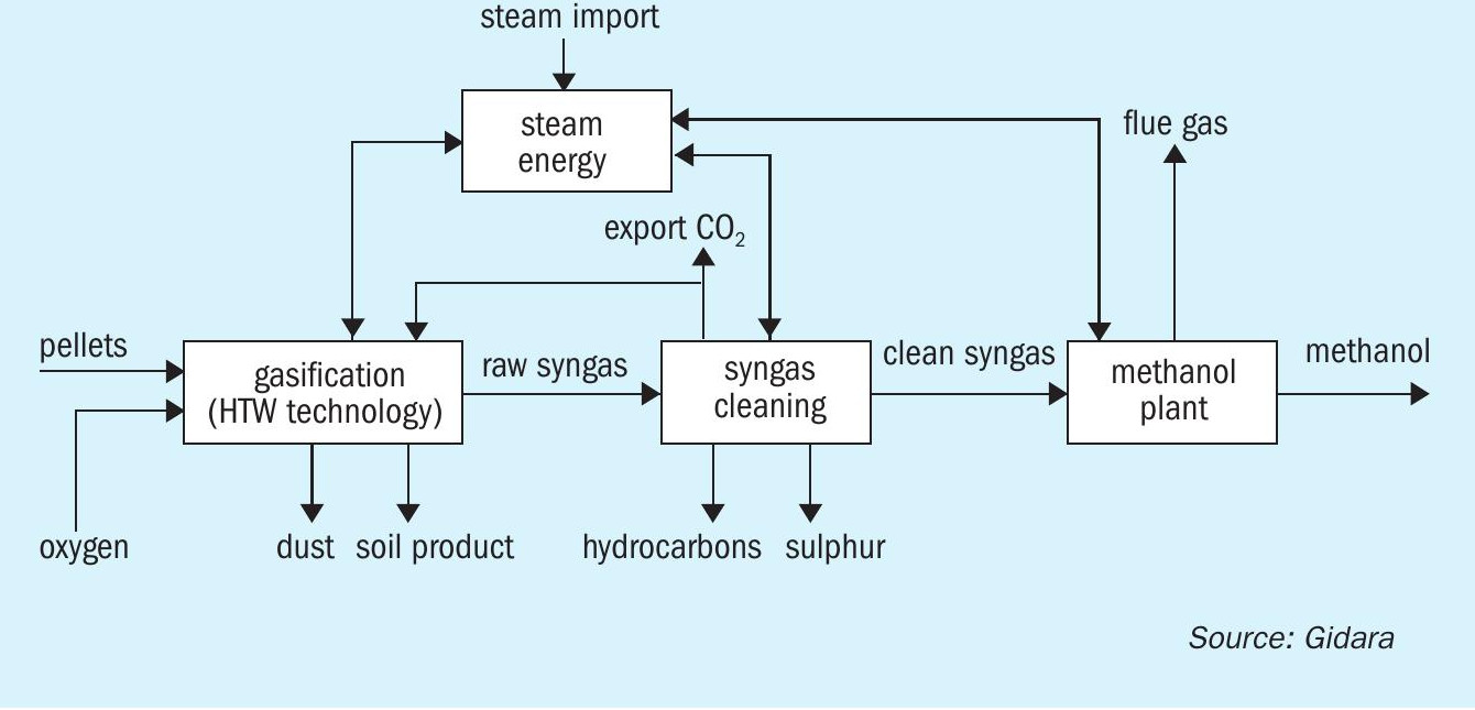
The methanol produced in the Advanced Methanol Amsterdam facility is based on the thermochemical conversion of carbonaceous feedstock, more specifically RDF and biomass waste material. The whole process can divided into three main process blocks. The first step is thermochemical biomass conversion using the High Temperature Winkler (HTW ® ) gasification technology to produce raw synthesis gas. In the second step the raw syngas is subjected to gas treatment, whereby the raw syngas is adjusted and cleaned, and the capture of CO 2 takes place. The clean syngas is then introduced to the methanol production unit where it is converted to methanol (Fig. 1).
State-of-the-art HTW® gasification technology
The HTW technology was originally developed for lignite feedstock in the 1920s by Rheinbraun AG in Germany. It was further developed in the 1970s by thyssenKrupp Industrial Solutions, together with Rheinbraun AG (now RWE AG) into a pressurised version of the Winkler gasifier which resulted in improvements that led to an increase in the carbon conversion efficiency thereby enhancing the quality of the produced syngas. In the 1990s the application of this technology towards bio-application began to be investigated. In 2010, the technology was acquired by thyssenKrupp Uhde and thereafter, by GIDARA Energy B.V., in 2019. Technology developments continued resulting in today’s state-of-the-art HTW ® gasification technology employed in the Advanced Methanol project which has the following key improved features:
- multi-media injecting nozzles along the height of the gasifier to provide subzonal-reaction spaces, targeting different reaction mechanisms;
- spiral flow pattern in the freeboard zone which results in achieving optimum reforming and tar-cracking reaction rates, thereby producing a tar-free brand of raw syngas;
- handling a wide variety of feedstocks comprising lignite, coal, peat, biomass, MSW, RDF, SRF, high plastic content waste, sewage sludge, etc.;
- provision of a quench system at the top of the gasifier which allows the exploration of higher temperature in the freeboard zone, assisting the production of the tar-free brand of raw syngas;
- smoothens the thermal stress effect on different location of gasifier pressure vessels while operating at different temperature ranges in the fluidised bed and free board zones.
AMA gasification unit
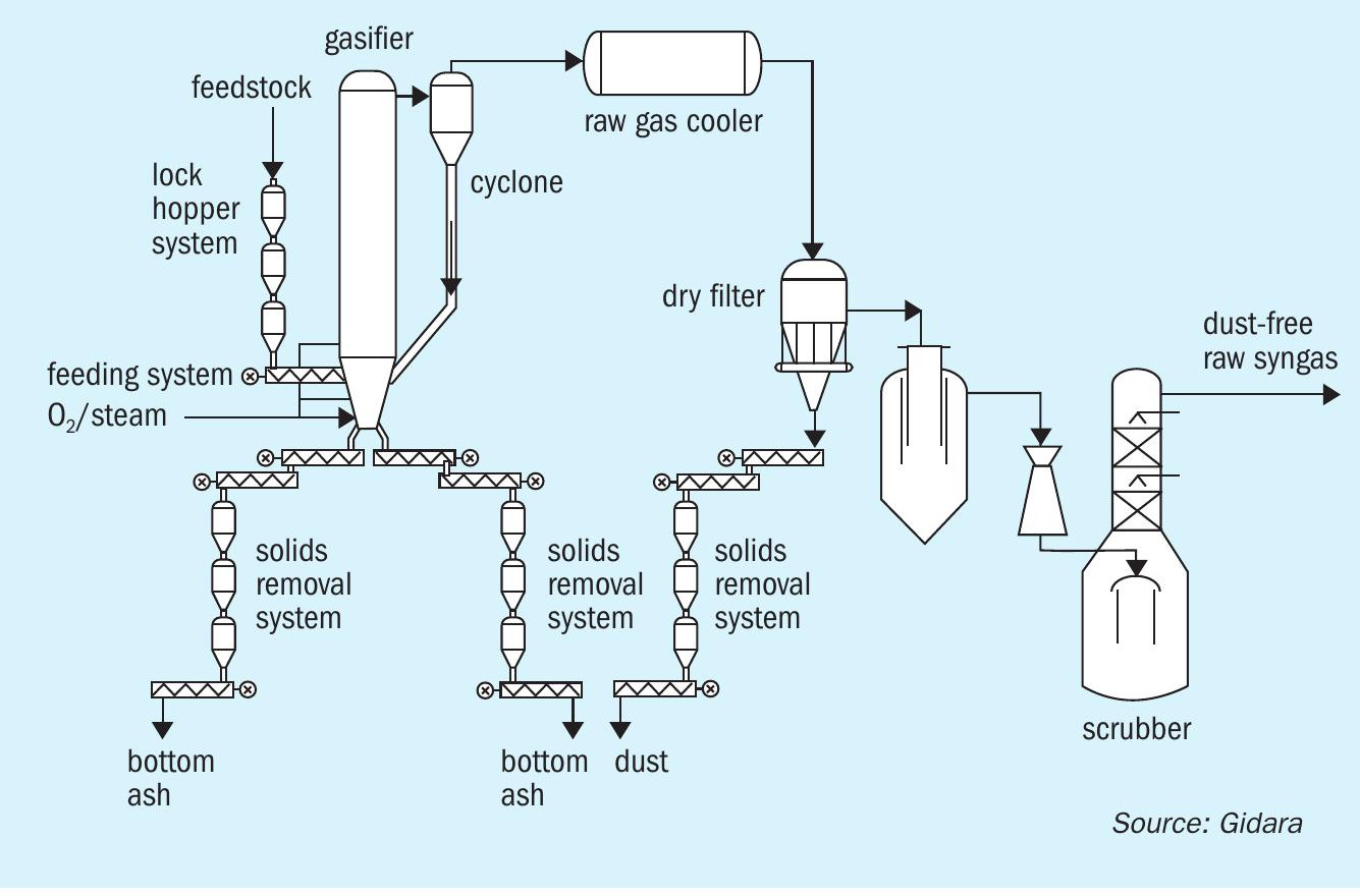
The gasification unit (Fig. 2) converts pelletised feed material (PFM) by means of thermochemical conversion (gasification) under pressurised conditions with the aid of oxygen, steam and CO 2 into raw syngas. The raw syngas is dedusted and chlorine components removed.
Pellet storage
The feed material (PFM) enters the facility at the pellet storage/handling area. The area provides a storage buffer for the PFM. From here, the PFM is distributed and transported to the feeding system at the top of the gasification unit where it is fed into two feeding trains of the gasifier.
Feeding system
The feeding system includes two identical feeding trains, each able to handle 60% of the gasifier capacity. In the feeding system the pressure of the PFM fed to the gasifier is increased from ambient pressure to gasification pressure. This pressurisation is achieved using CO 2 in a lock hopper system, leading to a charge bin again at pressurised conditions. This ensures leak-tight feeding of the PFM at the required pressure, to the gasifier. The feedstock is fed to the gasifier by means of cooled feeding screws.
HTW gasifier and raw gas cooling
In the gasifier, gasification takes place in a fluidised bed at a pressure of 15 bara, converting the feedstock material into syngas, bottom product, and dust. The conversion takes place by non-catalytic gasification reactions.
Overall, this set of reactions is endothermic and receives its heat from the partial oxidation of the feedstock and syngas by pure oxygen which is fed to the gasifier. Steam and CO 2 are added to control the equilibrium and produce the required syngas composition.
The gasifier comprises two main zones, the gasification and post gasification zones. Oxygen, steam, and CO 2 are supplied as gasification agents to the gasifier at a controlled flowrate through single or specialised multilayered nozzles. The gasification zone of the gasifier is a fluidised bed located in the conical part of the reactor. The fluidised bed is made up of solid remnants of the gasified PFM, also referred to as the bed material. This zone is operated under controlled conditions wherein temperature and the concentration of gasification agents are adjusted to enhance the conversion of the feedstock material towards gas components and fly-char. The converted material from the gasification zone enters the post-gasification zone, where the temperature is adjusted through a controlled supply of oxygen and steam. Here, the carbon content in the fly-char (entrained dust) is further converted in the presence of steam to produce carbon monoxide and hydrogen. In parallel, the intermediate hydrocarbon content of the raw gas undergoes steam cracking, thereby achieving a high carbon conversion efficiency. The high temperature condition in the post-gasification zone provides even further decomposition of intermediate hydrocarbons and tars.
The individual conversion reactions between the reagents are very complex. In simplified form, the reactions taking place in the gasifier can be summarised by the following basic equations:
C + O 2 → CO 2 ∆HR = -393.6 kJ/mol
C + ½O 2 → CO ∆HR = -123.1 kJ/mol
C + H 2 O → CO + H 2 ∆HR = +118.5 kJ/mol
C + CO 2 → 2CO ∆HR = +159.9 kJ/mol
C + 2H 2 → CH 4 ∆HR = -79.4 kJ/mol
CO + H 2 O → CO 2 + H 2 ∆HR = -41.1 kJ/mol
The raw syngas which leaves the gasifier at the top contains a considerable amount of entrained particles. The major portion of these particles is separated from raw syngas in the raw gas cyclone and returned into the fluidised bed zone of the gasifier through recirculation line.
The raw syngas leaving the HTW gasifier has at a high temperature and thus needs to be cooled to a temperature that it is more suitable for the subsequent process steps. This is done in a raw gas cooler, generating saturated high-pressure steam and cooled raw syngas.
Bottom product removal
Most of the carbon present in the feedstock material is converted together with oxygen and steam into raw syngas during the gasification in the fluidised bed, leaving the gasifier at the top to be further processed. The remaining nonconverted carbon material along with other inorganic solid components accumulate as ash at the bottom of the gasifier as the bottom product. This is withdrawn using cooled screw conveyors and guarantees the stable state of the fluidised bed. The screw conveyors cool and transport the bottom product to lock hoppers wherein the bottom product is depressurised with the help of CO 2 to ensure no syngas can escape with the bottom product. The bottom product is then pneumatically conveyed to storage silos where it is stored under inert gas conditions until it can be collected for transport.
Dry dust removal
The fine dust particles passing with the raw syngas through the gasifier cyclone must be removed in the dry dust filter to avoid plugging of the downstream processing equipment. To remove the dust a ceramic filter is used that gives a very high removal efficiency of the dust from the raw syngas. The dust is removed from the filters by pulses of CO 2 and collected at the bottom of the filter, from where it is removed in the same way as the bottom product, using cooled screw conveyors and a lock hopper system to depressurise the dust. After depressurisation dust is pneumatically conveyed to storage silos where it is stored under inert gas conditions until it can be collected for transport.
Quench and scrubbing The purpose of the syngas quench and scrubbing is to remove the corrosive component hydrogen chloride, and partly wash out ammonia, HCN and any residual dust by wet scrubbing and to saturate the raw syngas with water. To achieve this, the raw syngas is washed with water. The raw syngas, already de-dusted in the upstream hot gas filter unit is quenched with water and thus saturated in the immersion cooler. Subsequently, the quenched gas enters the raw gas scrubber. Surplus water is separated in the lower part of the scrubber. Packing elements and clean water on the top of the scrubber support the removal of the above-mentioned substances. The acidity of the process water system is adjusted by feeding caustic soda. The raw syngas leaves the raw gas scrubber at the top of the scrubber and is passed to the downstream gas treatment unit. Surplus water from the system is released as wastewater by level control from the immersion cooler to the wastewater treatment area.
AMA gas treatment
In the gas treatment section, the raw syngas is adjusted to the required compositions and cleaned to remove impurities producing clean syngas, before it is introduced to the methanol production unit. It is critical for the methanol production to receive the syngas at the right composition. Also, the removal of the impurities is important as they can poison the catalyst used in the methanol synthesis The gas treatment unit consists of four process areas, namely, raw syngas adjustment, acid gas removal, sulphur removal and CO 2 polishing.
Raw syngas adjustment
The objective here is to process the raw syngas from the gasification unit and to produce adjusted syngas. The raw syngas adjustment area consists of the following process sections:
- CO shift conversion over a catalyst to adjust the CO and H 2 ratio achieving one required for the downstream methanol unit;
- HCN and COS hydrolysis to convert the HCN and COS to NH 3 and H 2 S, respectively, over a catalyst bed;
- heat recovery;
- compression.
Raw syngas adjustment produces:
- adjusted syngas, the outlet stream from the compressor, which will be further processed in the downstream acid gas removal;
- process condensate by-product is sent to wastewater treatment.
Acid gas removal
The technology used for acid gas removal is Linde’s Rectisol wash unit (RWU) for treatment of a partly shifted gas. Here, a physical wash agent is utilised to remove contaminants such as H 2 S, COS, HCN, and higher hydrocarbons as well as bulk CO 2 removal from the adjusted syngas feed down to the required specifications for methanol unit. The lean wash agent facilitates simultaneous “washing out” and absorption of the above-mentioned impurities. Loaded wash agent is then regenerated and recycled back with any losses being compensated via make-up.
Acid gas removal produces:
- purified syngas, free of H 2 S/COS and with a minimal concentration of CO 2 , suitable for methanol synthesis;
- acid gas by-product, consisting mainly of CO 2 and H 2 S, which will be further treated to produce clean CO 2 product.
- hydrocarbon by-product, consisting of benzene and naphthalene.
Casale methanol process
Casale has implemented the most appropriate customisation of the Flexigreen methanol standard scheme to design the methanol generation sections for AMA project.
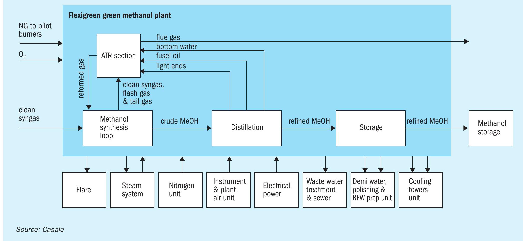
Units involved in Casale scope are: the synthesis loop, the autothermal reformer (ATR) section, the distillation section and the crude and refined methanol daily storage section.
Fig. 3 shows a block flow diagram of the green methanol plant.
Casale methanol process main sections
Methanol synthesis loop
The aim of the methanol synthesis loop section is to convert synthesis gas into methanol.
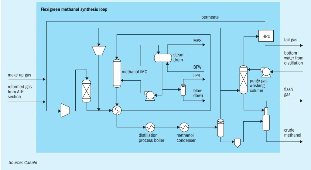
Overall, the synthesis loop (Fig. 4) is very simple notwithstanding it is very efficient and the heat integration with the distillation section plays a key role: there are only eight main items of equipment.
The make-up gas from upstream units mixed with the hydrogen-rich streams from the hydrogen recovery unit (HRU) and the ATR section, after compression in a dedicated compressor, is sent to a catalyst guard bed where sulphur compounds, still present in the make-up gas from upstream units, are removed. The aim of the guard bed is to reduce the total sulphur concentration in the gas after desulphurisation catalyst adsorption below 0.02 ppm vol.
The compressed stream is mixed with the recycle gases at the discharge of the circulator and routed to the gas-gas heat exchanger where it is heated up to converter inlet temperature using the heat of synthesis converter effluent product.
The feed gas enters the converter (an Isothermal Methanol Converter, IMC) and directly flows to the catalyst isothermal zone, where the methanol synthesis reaction takes place. As the gas crosses the isothermal zone, the reaction proceeds while the temperature is kept almost constant by releasing the reaction heat to the plates, wherein medium pressure steam is raised. The plates inside the converter act as a boiler with forced circulation.
The converter outlet gas is first routed to the gas/gas heat exchanger, then to the topping column gas heated reboiler and finally to the trim condensers where the final condensing temperature is reached.
Crude methanol is separated in the high-pressure separator, then let down to low pressure in the low-pressure separator where dissolved vapours are washed counter currently by a mixture of water and methanol from the purge gas washing column. Gases from the low-pressure separator (flash gas) are sent, as fuel, to the ATR section, while the crude methanol is sent directly to the distillation section.
From the top of high-pressure separator, the vapours containing non-converted reactants are mainly recycled back to the synthesis loop through the syngas compressor circulator. A stream of purge gas is removed from the recycle gas in order to control synloop inerts level and is routed to the purge gas washing column, where it is washed by a portion of bottom water from the distillation section to recover the produced methanol. Washed purge gas from the top of the column is sent to the HRU unit to recover as much hydrogen as possible. Recovered hydrogen is recycled back to the synthesis gas compressor suction while the tail gas from HRU unit is sent, as feed, to the ATR section.

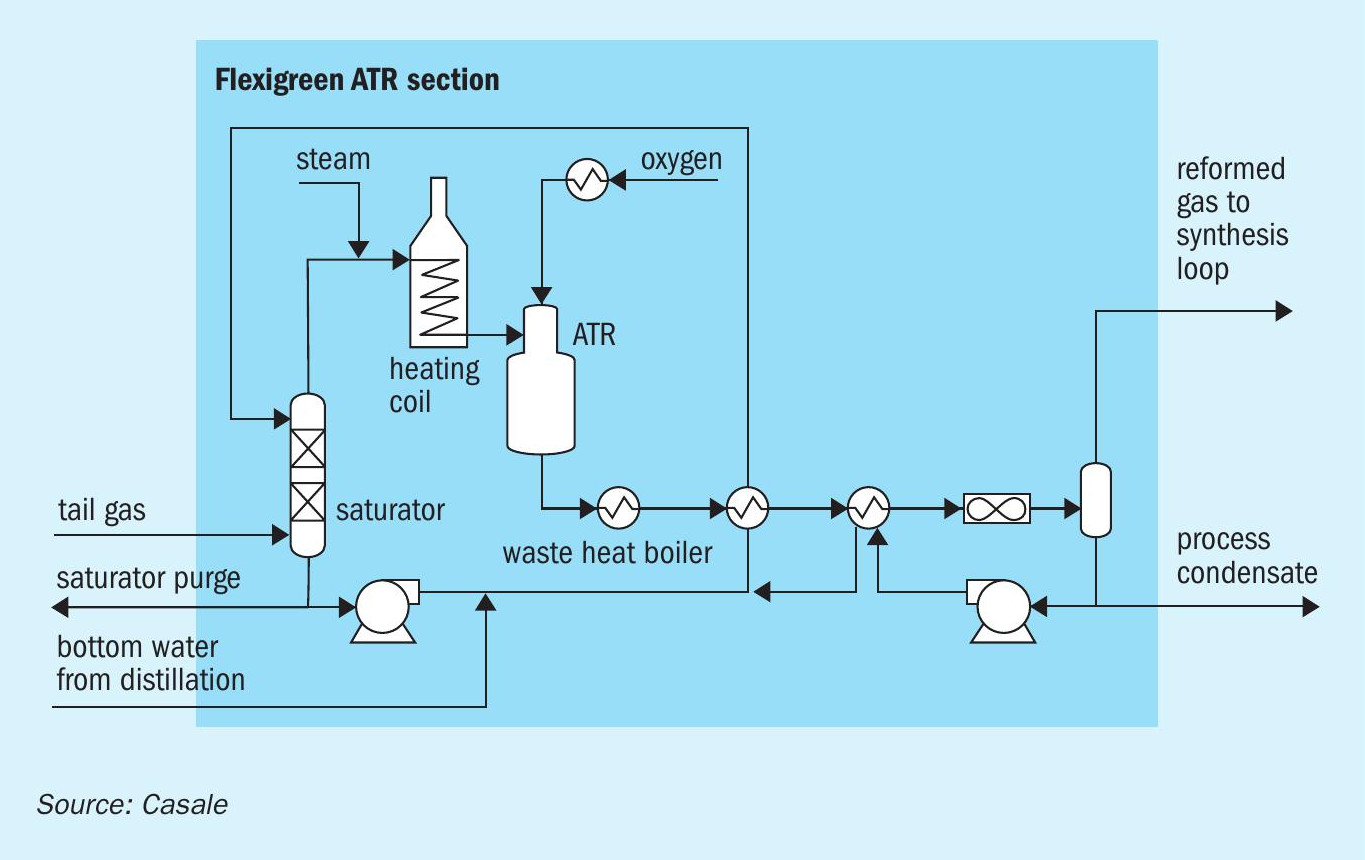
ATR section
The purpose of the ATR section (Fig. 5) is to convert the methane present in the tail gas from the HRU into synthesis gas via steam reforming.
The major portion of the tail gas is sent to the ATR feed gas saturator. Make-up water to this column is the complementary part of the bottom water from the distillation section and a portion of the process condensates from the condensate separator installed at the end of ATR train. The saturated gas is mixed with a suitable steam flowrate and heated up to a suitable ATR inlet temperature in a furnace in the dedicated ATR feed preheater coil. This stream is routed to the Casale patented ATR burner where it is properly mixed with a preheated pure oxygen stream. The burned mixture reacts on a catalytic bed where syngas is generated via steam reforming. The reformed gas is cooled down in a waste heat boiler (generating high-pressure steam), then in the saturator circulation heaters and finally in an air cooler. The gaseous stream, rich in hydrogen and carbon oxides, can be recycled back to the suction of the synthesis compressor as additional make-up gas to the methanol synthesis loop. The process condensates from the condensate separator are partially pumped and recycled back as make-up water to the saturator tower while the other portion is diverted from the methanol unit to other complex sections.
Continuous cooling of the ATR burner is assured by circulating boiling feed water flowing in the burner itself.
Installation of a fired heater is necessary for two main reasons:
- reaching the suitable ATR inlet temperature;
- burning all the waste streams produced in the methanol plant. Waste streams are produced in the methanol purification process (i.e.: flash gas, light ends and fusel oil). Additionally, it is necessary to divert from the system a quote of purge gas (more specifically a quote of tail gas from HRU) to keep at an optimised level the inert gases concentration such as nitrogen and argon in the methanol synthesis section.
In addition to the main process service (ATR feed pre-heating), the fired heater has been designed in order to maximise the heat recovery through BFW preheating and high-pressure steam superheating.
The fired heater is equipped with a selective catalytic reduction (SCR) system to minimise flue gas composition environmental impact.
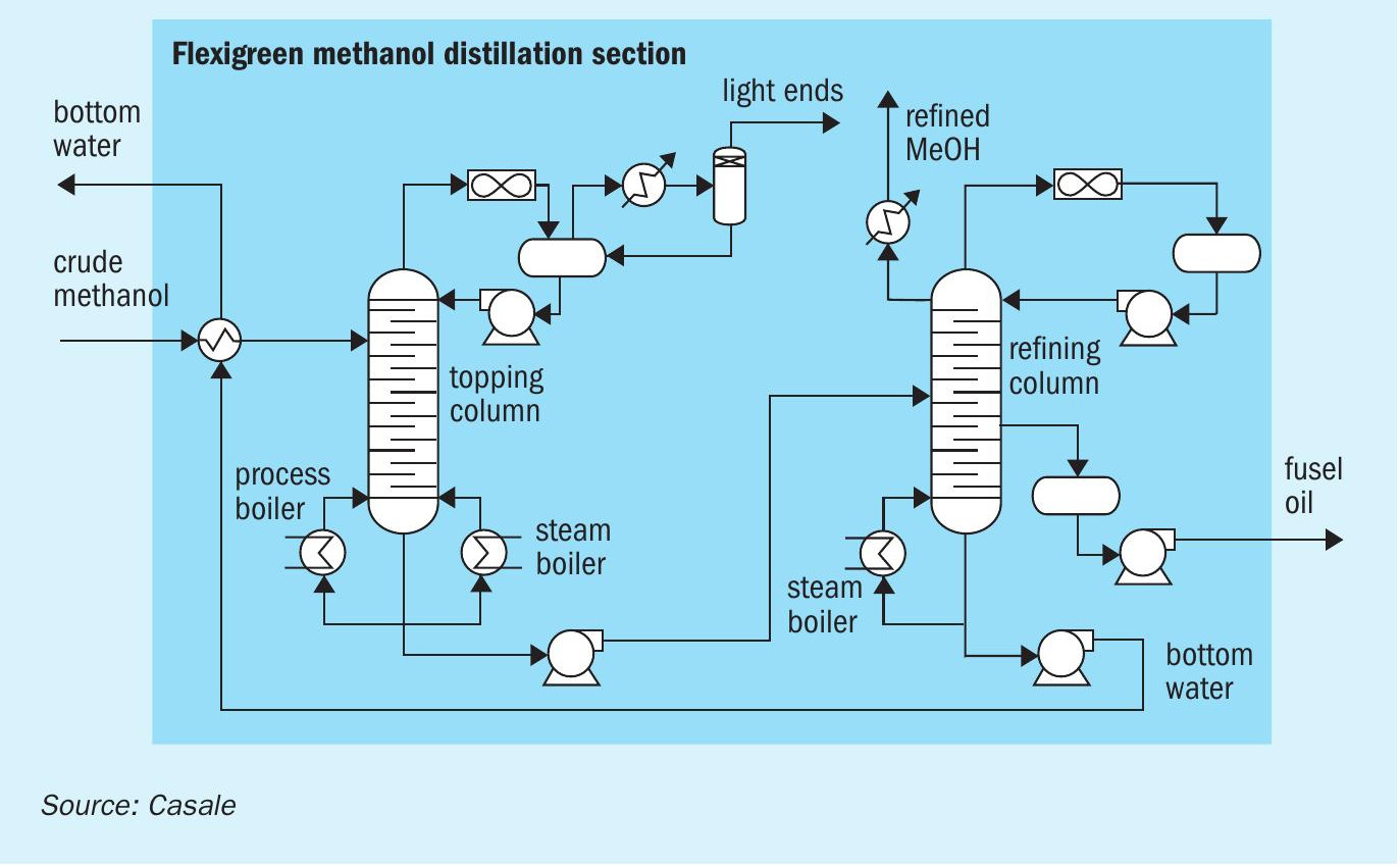
Distillation section
Purification of the crude methanol generated in the synthesis section occurs in the distillation section (Fig. 6). Only two distillation columns are typically foreseen in the Casale Flexigreen methanol distillation section: one topping column and one refining column.
The components which are more volatile than methanol (namely the light ends) are separated in the topping column fed with the crude methanol directly from synthesis loop.
The conventional distillation tower top operating pressure is 0.6 barg.
The light ends components leave the column from the condensing section at the top of it while the reboiling duty is supplied thanks to a process reboiler installed in the synthesis loop and a LP steam reboiler.
The topped crude is pumped to the refining column where the components, which are less volatile than methanol, are removed.
The conventional distillation tower operates at a pressure slightly above atmospheric. It is provided with a full condenser and an LP steam reboiler. In this column, water and heavier impurities are removed from methanol product.
Refined methanol is extracted from the top portion of the column while the bottom water is taken off at the base of the column and pumped to methanol synthesis and ATR sections.
A few trays from the bottom of the tower there is a sufficient concentration of heavier components (namely fusel oils) to allow them to be purged from the system and routed, as fuel, to the ATR section.
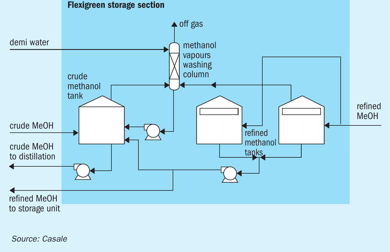
Storage section
The storage section consists of a crude methanol tank and two refined methanol tanks and their pumps (Fig. 7).
The crude methanol tank is a conical fixed roof while the refined methanol tanks are floating roof tanks. All tanks are sealed with nitrogen to avoid air contamination which can cause product deterioration and inflammable mixture. To minimise methanol emissions to the atmosphere a washing column washes all vapours from all the tanks with water.
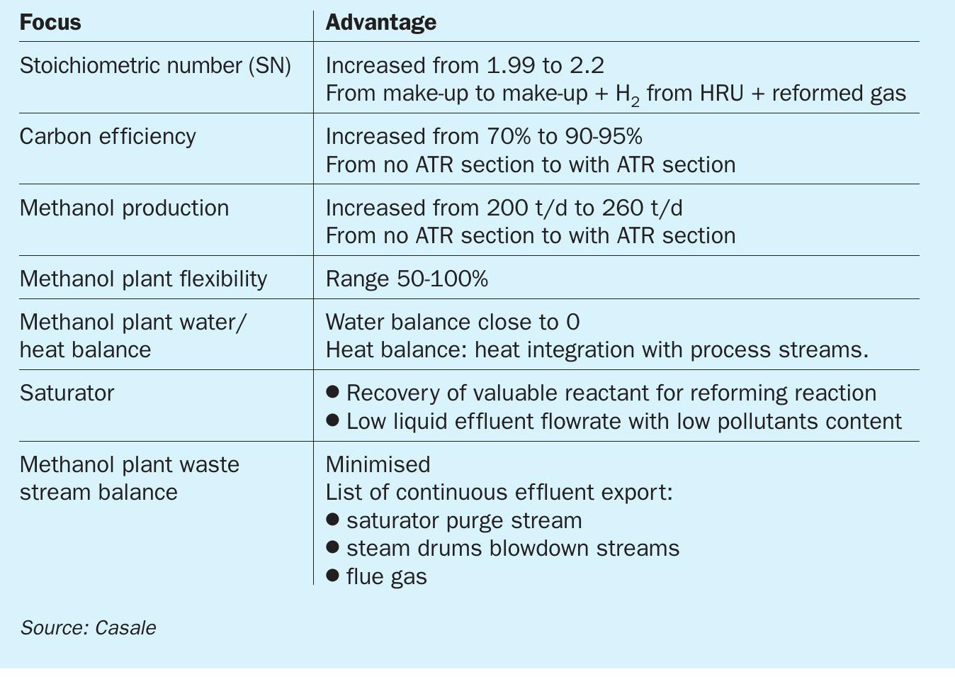
Advantages of Casale process scheme
Table 1 shows the advantages of the Casale process scheme.
SN, carbon efficiency and methanol production
A peculiarity of methanol generation from biomass used as the carbon source is the composition of the feedstock of the methanol synthesis loop, namely the composition of the synthesis or make-up gas, which is rich in carbon oxides and methane, but poor in hydrogen.
For optimised generation conditions (optimum stoichiometric number) and a high yield in methanol production (high carbon efficiency and production), the Casale approach foresees:
- optimisation of the methanol plant make-up gas composition through the upstream shift and acid gas removal sections;
- recovery of the hydrogen present in the synthesis loop purge gas via the HRU unit;
- the highest exploitation of the carbon content of the make-up stream through a dedicated tail gas from synthesis loop conversion section: the so-calledATR section. In the ATR section the tail gas from HRU unit, rich in methane, is converted via steam reforming reaction in synthesis gas.
Methanol plant water/heat balance
The total water balance of the methanol section generation is closed to zero. The plant imports boiling feed water, demiwater and LP steam, and exports a corresponding flow of boiling feed water, MP steam, superheated HP steam, LP steam condensate and process condensates, thanks to process and bottom distillation water reuse in methanol plant battery limit as well as deep heat integration. The ATR section is characterised by HPS generation in the waste heat boiler and saturator circulation heaters downstream of the ATR reactor, while boiling feed water pre-heating and HP steam superheating occur in the fired heater. This heat recovery, together with the medium-pressure steam generation in the IMC reactor and with the exploitation of the condensing synthesis loop gas downstream of the IMC which is able to supply heat to the distillation section (via process gas heated topping column reboiler), provide an almost self-sustaining unit in terms of heat/water demand: only low-pressure steam import for methanol distillation is expected while the overall steam export (medium-pressure steam export + high-pressure steam export) during normal run is slightly higher than the low-pressure steam import.
Saturator
In the ATR section, the tail gas is saturated in the saturator tower. The steam gained in the tower depends on the quantity of heat recovered downstream of the ATR reactor by the saturator circulating water. In this way, a decrease of import of valuable HP steam is achieved.
Since a portion of the process condensate and bottom water from the distillation section are used as make-up streams for saturator circulating water, two additional advantages are achieved:
- pollutants contained in these two make-up streams (such as traces of methanol synthesis by-products and syngas) are stripped out and recovered as reactants for the reforming reaction;
- a lower liquid effluent flowrate with a lower quantity of pollutants to be disposed of.
The methanol plant waste stream balance from the Flexigreen methanol solution envisages the minimum export of waste streams.
Common waste stream such as tail gas from the HRU, flash gas, light ends stream, fusel oil and bottom water from the distillation section are all recycled in the methanol plant BL. The actual continuous waste emissions which are exported from the methanol unit are: the saturator purge stream, the steam drums blowdown stream and the flue gas from the fired heater stack.
Key Casale proprietary items for green methanol
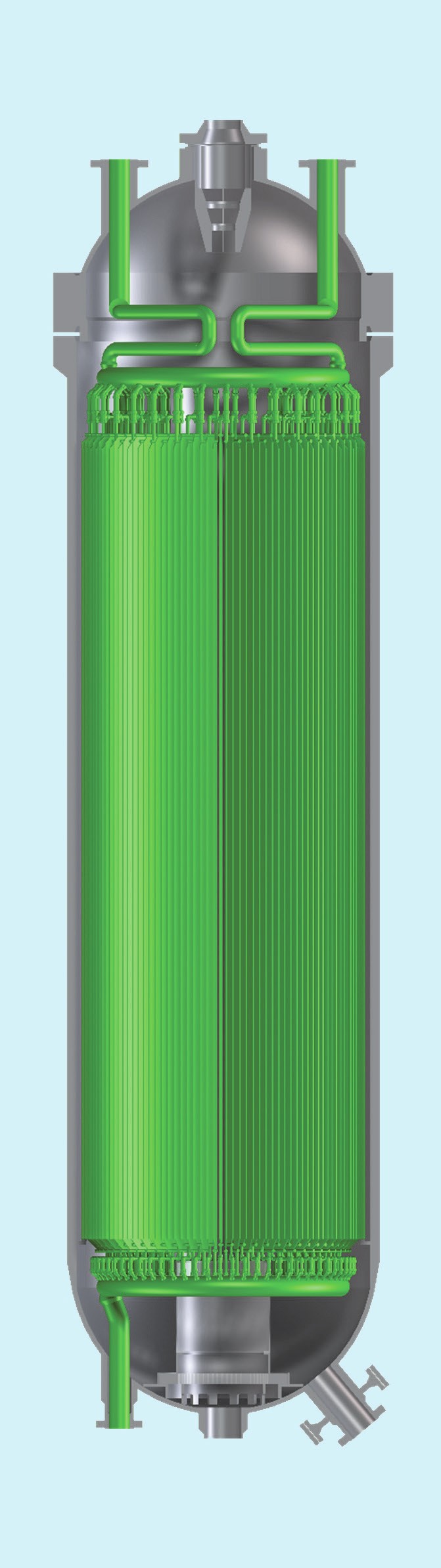
Isothermal methanol converter
The methanol converter (Fig. 8) The methanol synthesis converter is the key piece of equipment for the methanol synthesis: its design influences the stability of the total system as well as the maximum obtainable synthesis make-up gas conversion into valuable product.
Over the last decades, Casale has developed and optimised its methanol converter to address all possible constraints including new eco-friendly requirements, resulting it in the isothermal methanol converter.
The distinguishing feature of this layout is that the heat released by the methanol generation reactions in the catalytic bed is absorbed by a cooling medium flowing in plates. The cooling medium can be either synthesis gas or boiling water whose selection is based on the quantity of generated heat and heat and material balance of the complex.
Plates give the flexibility needed by a fruitful technology to cover different demands. They can be designed in radial configuration and, therefore, they can overcome the common tube layout design constraint: the tubesheet. With this design, the distribution of both water and gas in the plates is guaranteed by dedicated collectors installed in the pressure vessel.
The most significant features of the Casale IMC design are:
- presence of only one continuous layer of catalyst;
- no catalyst by-pass: the reacting gas flows through the entirety of the catalyst volume;
- better performance, resulting from the advanced design, ensuring the best catalyst temperature profile with l the highest uniformity;
- suitable design of the heat exchange elements for this particular service and the critical environment in which they have to operate (catalyst loading and unloading, thermal expansion, mechanical stress, corrosion stress);
- easier mechanical construction;
- highest reliability thanks to the industrialised and automated production process of the reactor’s internal components;
- easier catalyst replacement and maintenance of the internals;
- flexibility to use any first-class commercially available catalyst;
- Casale experience in designing synthesis converters.
At present, 26 Casale isothermal plate cooled methanol converters are on stream and others are under construction/engineering, with capacities ranging from 260 t/d to 8,000 t/d, the latter in a single vessel. The total worldwide installed capacity using Casale Converters (of several different types: adiabatic quench cooled, adiabatic interchanger cooled, isothermal plate cooled) is about 30% of the current total world capacity.
ATR reformer design and ATR burner
The ATR is a bottle-shaped reactor in which the methane steam reforming reaction to generate synthesis gas occurs. It is characterised by a catalytic bed installed in a refractory-lined pressure vessel. The Casale ATR design is conceptually very simple. The bottle-shaped reactor can be divided into two parts: the top cylindrical part and the bottom cylindrical part. The burner is installed in the top, and the catalyst bed is in the bottom.
The methane-rich gas is introduced from one side at the top of the low-diameter cylindrical chamber (top cylindrical part), before the burner tip, perpendicular to the burner. The oxygen stream is introduced at high velocity axially at the top of the bottle-shaped reactor inside the burner. The high velocity of the oxygen causes mixing between the two streams and the combustion reaction takes place instantaneously after mixing. A circular distributor with a small pressure drop is provided upstream of the burner tip to obtain a uniform flow of methane-rich gas before it is mixed with the oxygen. The combustion chamber length is chosen in order to avoid impingement of the burner flame over the reforming catalyst while achieving an almost uniform distribution of temperature and gas composition at the chamber outlet before the catalyst bed. The impingement of the flame on the catalytic bed would damage its superficial layer resulting in performance losses (higher methane slip) and increased pressure drop.
The fluid-dynamic flow field inside the combustion chamber is designed to protect the refractory lining from the high temperature core of the flame, preventing hot spots on the lining surface. The burner tip is provided with a forced convection cooling water system to protect the burner from the high combustion temperature. The water path inside the burner tip ensures uniform cooling of all the burner walls. In particular, the heat transfer coefficient of the water flow has been enhanced according to the tip that is near the flame.
Besides the solutions implemented by Casale in the design of the reactor itself, the ATR burner is also a proprietary item, designed and supplied by Casale. The design of the Casale ATR burner relies on CFD tools used to simulate the flow and temperature fields inside the combustion chamber and within the burner body, taking into account the strong correlation between turbulence and chemical kinetics. The CFD results are also coupled with thermal and FEM analysis of the burner’s solid surfaces, which are essential to understand and optimise the burner design. These calculations are confirmed by industrial experience. The approach followed by Casale addresses most of the common problems relating to reformer burners such as poor mixing, soot formation and overheating of the surfaces exposed to the flame.
The main features of the Casale pure oxygen autothermal reformer burner are:
- Good mixing between oxygen and natural gas, with an almost uniform field of temperature, velocities and composition at catalytic bed entrance:
– Achieve a better equilibrium approach due to almost uniform temperature and composition at the catalytic bed inlet.
– A shorter flame; avoiding the impingement of the flame on the catalytic bed thus resulting in longer life of the catalyst, better performances and no pressure drop increases due to sintering/milling.
- Soot-free operation.
- High flexibility in operation, allowing running the burner with good performances in a wide range of flow rates.
- Low temperature of the reformer refractory lining.
- Water-cooled burner tip in order to ensure several years of safe operating life with low temperature of the burner surfaces exposed to the flame:
– No plant shutdown related to burner failure.
– Proven trouble-free operation.
– Up to eight years of proven operation with a single Casale burner.
- Flame stability.
Casale has acquired sound experience in the design of ATR reactors for both ammonia and methanol production and for both two-step reforming and pure ATR (with coke oven gas) configurations. Casale has several referenced ATR reactors for methanol production in operation or scheduled for start-up, with capacities ranging from 350 to 7,000 t/d. At present there are 9 units in operation, including a 5,000 and a 7,000 t/d methanol plants. n