Nitrogen+Syngas 386 Nov-Dec 2023
30 November 2023
Application of CFD for optimisation of waste heat boilers
PLANT EQUIPMENT
Application of CFD for optimisation of waste heat boilers
Steinmüller Engineering shares its experiences of applying CFD to re-design the waste heat boiler downstream of the secondary reformer to successfully achieve the desired uniform cross flow across the tube bundle.
The waste heat boiler (WHB) downstream of the secondary reformer is one of the most critical heat exchangers in ammonia and methanol plants. Typical reformer outlet gas temperature is in the range 900 to 1,050°C while pressure varies between 25 and 35 bar. Due to these gas conditions and the demand for rapid cooling down the WHB has to cope with a high specific heat flux density > 500 kW/m². Flow imbalances and undesired bypasses affect efficiency and may even lead to local overheating. In order to achieve a high thermal efficiency, as well as to prevent severe damage, sophisticated process know-how is required to understand and to optimise the WHB.
Thermodynamic software tools for heat exchanger design require input with respect to the efficiency of the heating surfaces as well as for any proportion of the gas flow bypassing the tubes. To include those effects in the thermal design even for complex geometries the design engineer needs additional tools.
In the last decade computational fluid dynamics (CFD) has been established in many fields of application to investigate physical phenomena and to optimise process related components.
Coupling results from CFD simulations to thermodynamic design enables the process engineer to further optimise critical static equipment by science-based analytical tools.
Thermal design challenges
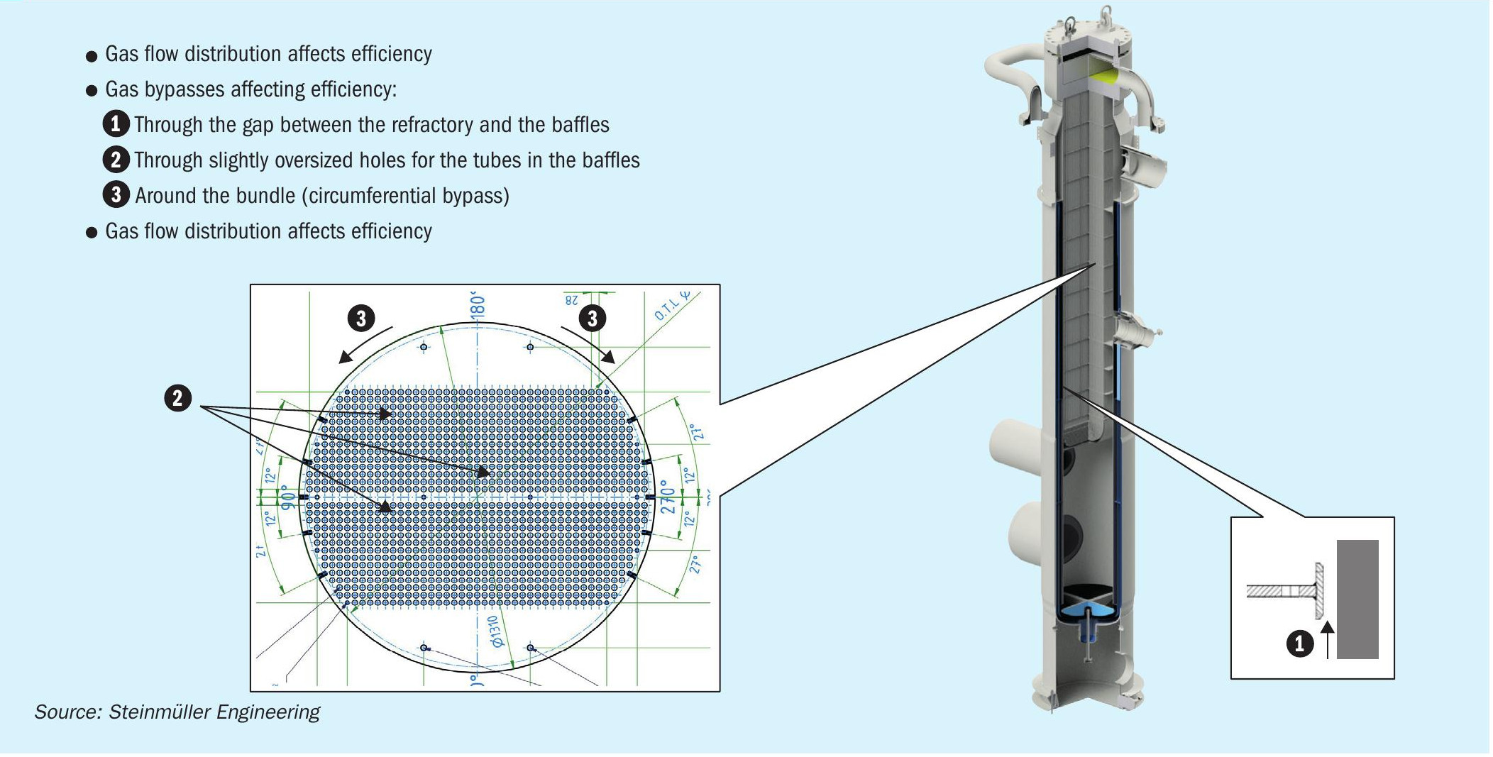
Fig. 1 shows areas in which bypasses occur on a typical U-bundle WHB. In addition, the gas flow distribution in the bundle itself also affects the thermal efficiency. While thermodynamic software calculates on the pre-assumption of an ideal cross flow, the situation is more complex.
CFD simulations
Standard CFD simulations cover the fluid flow only. Solid material is typically modelled as a dimensionless wall (s = 0 mm) with defined thermal boundary conditions to include heat transfer from fluid to the wall. For the purpose of optimising the WHB design the solid material of the baffles has to be part of the model in order to allow a prediction of the temperature profile to derive the thermal expansion.
The WHB was simulated by Steinmüller Engineering in a 3D CFD model using porous media properties to model the flow resistance and the heat transfer inside the tube bundle. The complete bundle was split into 20 sections with individual heat take up, derived from a first thermodynamic model.
The model delivers patterns of gas flow velocities, pressure drop and also temperature profiles. However, many design details cannot be included in a global model because a proper mesh geometry with a reasonable number of cells is required.
To investigate areas where a detailed geometrical model is required, smaller sub models were developed.
Results and solutions derived from CFD simulations
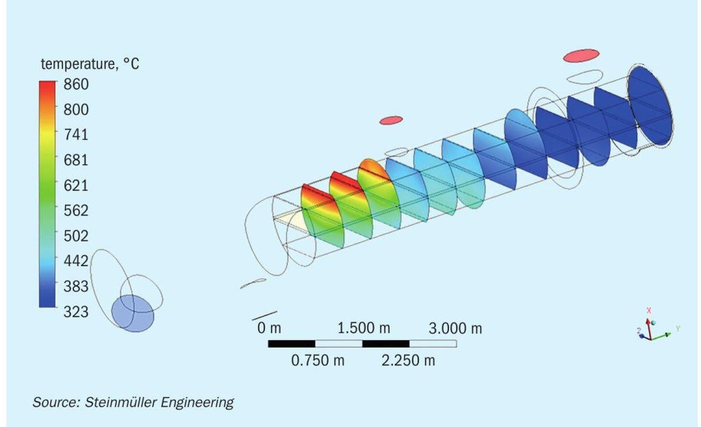
As a counter measure to the type 1 bypass between baffle plates and refractory, a CFD simulation assists in evaluating the order of magnitude of the bypass. In addition, the effective baffle material temperatures can be estimated (Fig. 2) and so the thermal expansion can be calculated for each individual section. With these data the remaining gap can be minimised.

In order to prevent type 3 bypasses a set of sealing strips was implemented. The efficiency of those strips was modelled by a 2D simulation of the tube bundle area.
The optimisation of the velocity profiles is the most important focus of the CFD simulation. The upper part of Fig. 3 shows the velocity profile for a non-optimised WHB.
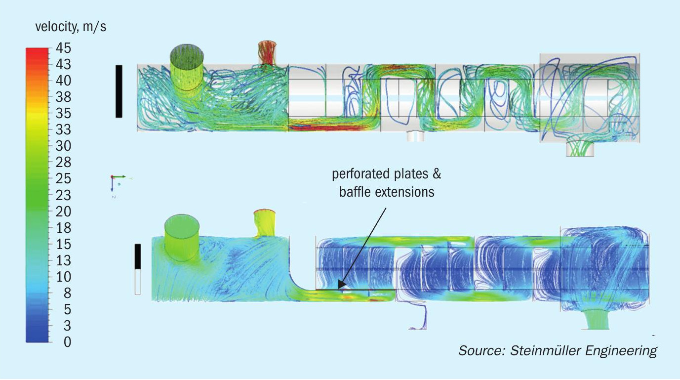
Due to the conservation of momentum the hot gas tends to flow almost in parallel along the first pass of the WHB unless the first baffle plate forces a 90° turn. In large areas of the tube bundle there are significant swirls and low flow, whereas the last section has to cope with very high velocities bearing a very high heat flux.
The poor velocity distribution affects the efficiency of the WHB and is either balanced by a high fouling factor or an additional degradation factor.
Steinmüller Engineering’s experience of applying CFD to correct flow patterns in the power industry was used to correct the flow behaviour. The baffles were extended in a manner to guide a gas proportion towards the bundle. In addition, a set of perforated plates was installed upfront of the tube bundle to balance the flow and to establish an almost perfect cross flow.
Conclusion
A conventional design for waste heat boilers is based on empirical heat transfer correlations, derived from experiments providing ideal flow conditions. In addition, due to the significant change of gas properties in the WHB, the ordinary correlations to estimate bypass impacts are not sufficiently precise.
The lessons learnt from applying CFD in various industries were used to optimise one of the most challenging heat exchangers in the synthesis gas process. The simulations allowed the engineer to judge the efficiency of counter measures for bypasses and enabled the desired uniform cross flow across the tube bundle to be achieved.