Fertilizer International 520 May-Jun 2024
31 May 2024
Phosphoric acid plants – engineering by experience
PROJECT ENGINEERING
Phosphoric acid plants – engineering by experience
How does an engineering company complete the basic and detailed engineering for a phosphoric acid plant – and provide the full design for the off-site sections and utilities? Jan Tytgat, De Smet Agro’s Process Engineering Manager, explains an approach based on partnership with the technology licensor and client that combines engineering expertise with experience.
Successfully designing a new phosphoric acid plant requires a combination of experience and know-how. De Smet Agro is Prayon’s most experienced engineering partner with an unparalleled track record, having completed the design of numerous phosphoric acid projects globally during the last 60 years.
Each new phosphoric acid plant (PAP) project begins with a process design package (PDP) from Prayon, the technology licensor. This is usually prepared from pilot phosphoric acid production tests on a phosphate rock concentrate. The engineering company (technology licensee) then proceeds with the following project phases:
- Basic and detailed engineering to complete the phosphoric acid plant process design.
- Provision of full and detailed mechanical, piping, civil & structural, electrical & instrumentation design and a 3D-model of the PAP.
- Complete engineering for off-site sections and utilities.
- Preparation of the capex estimate and a preliminary financial model, if required.
- Construction supervision and participation in plant commissioning, training and start-up activities.
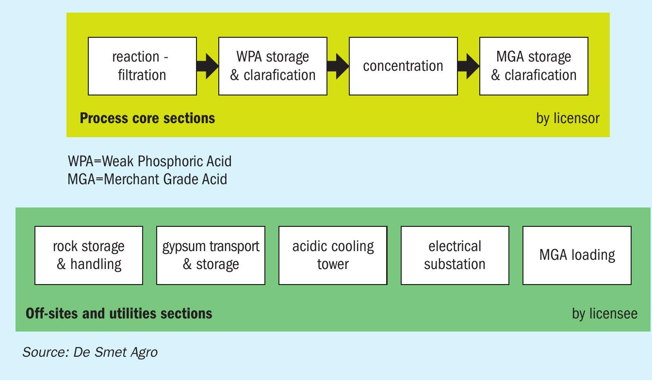
The overall design concept for a phosphoric acid plant and the respective engineering activities of the licensor (Prayon) and the licensee (De Smet Agro) are summarised in Figure 1. Essentially, the licensor is responsible for core phosphoric acid process activities, while the licensee handles off-site sections and utilities.
The off-site section design includes complete engineering for:
- Storage, handling and loading/unloading of the phosphate rock raw material
- By-product removal/storage – phosphogypsum and fluosilicic acid
- The acidic cooling tower
- The electrical substation
- Final product loading – concentrated phosphoric acid or merchant grade acid (MGA).
Phosphate rock
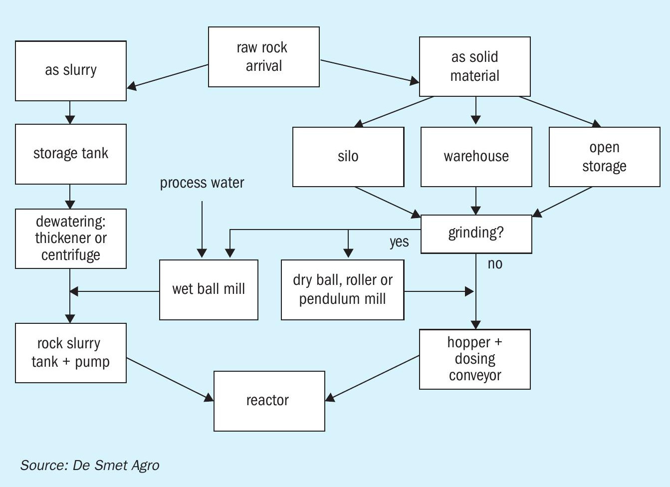
Phosphate rock handling, storage and dosing – for both dry solids and slurries – are summarised in Figure 2.
Phosphate rock concentrate is often imported by ship or brought directly from the mine to the plant by rail or truck. It is then unloaded and carried to an open storage area, a silo or a warehouse. Even solid phosphate rock can still contain up to 12 percent moisture, depending on the upstream beneficiation and drying process. Open storage is not generally recommended when other facilities and plants are located nearby. Phosphate rock, if fine and dry (less than two percent moisture), can be carried by the wind and form unwanted piles within the plant’s boundary.
If desired, phosphate rock blends can be prepared on site from different quality rock sources using payloaders and belt conveyors.
The installation of a rock grinding unit may be necessary, depending on the final particle size requirements of the selected phosphoric acid production process. A ball mill, a roller mill or a pendulum mill can be used. The grinding assembly typically consists of:
- A dosing hopper and weighing belt conveyor
- A set of conveyors and elevators
- Hot air injection
- The grinding mill fitted with a fan and ducts for ground rock
- A ground rock silo, separator and a dedusting system.
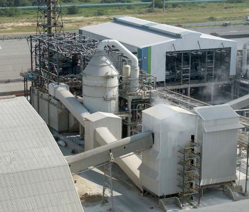
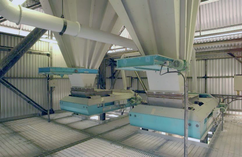
Conditioned phosphate rock is conveyed to a buffer hopper (see photo) – usually sized for a few hours production capacity – and then dosed on a weighing belt conveyor for onward transport to the phosphoric acid reaction tank via a belt or chain conveyor.
For some projects, raw rock is mixed with process water and sent to a wet ball mill, an option that is almost dust free and does not require hot air transport. The resulting ground phosphate rock slurry is sent for storage in a slurry tank.
Phosphate rock storage capacity will mainly depend on the frequency of raw material deliveries. If the rock is brought in by ship once monthly, for example, storage must be sufficient to receive this shipload and ensure a minimum of one month’s production. The capacity of ship unloading equipment and conveyors must also enable transfer of the cargo from ship to storage in the shortest possible time.
The rock handling capacity between the storage and the reactor, on the other hand, will depend on factors such as plant capacity, the P 2 O 5 and water content of the rock, and expected plant yield. Typically, imported phosphate rock contains 30-38 percent P 2 O 5 and 1-3 percent moisture.
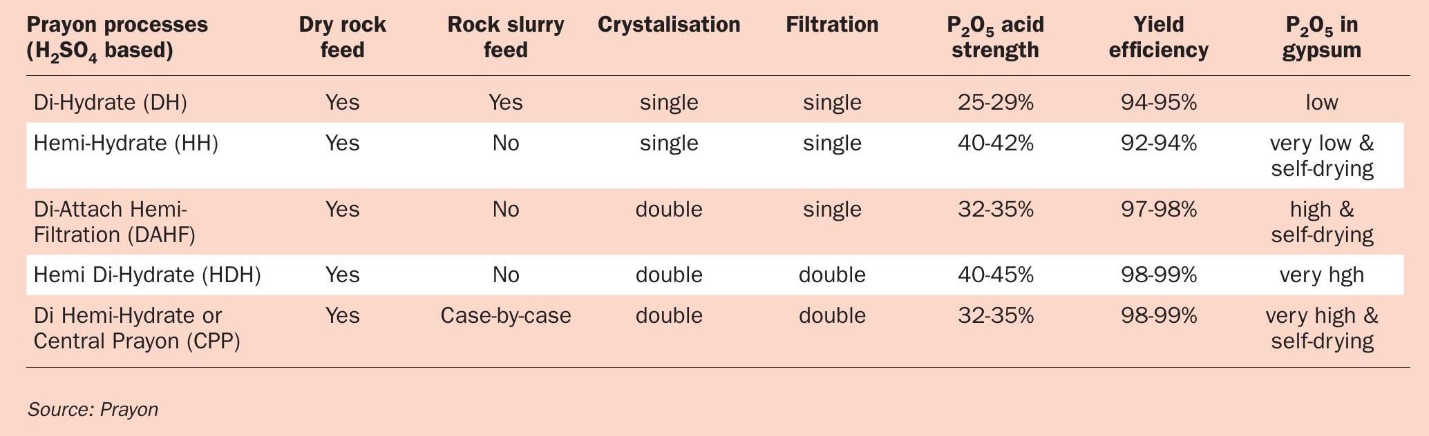
A dry rock feed to the phosphoric acid reactor is usually preferred, as slurry feed is not suitable for all types of phosphoric acid process (Table 1). Use of a dry feed also prevents the (sometimes accidental) overdosing of process water to the reactor that can occur with slurries.
Water balance – an important consideration
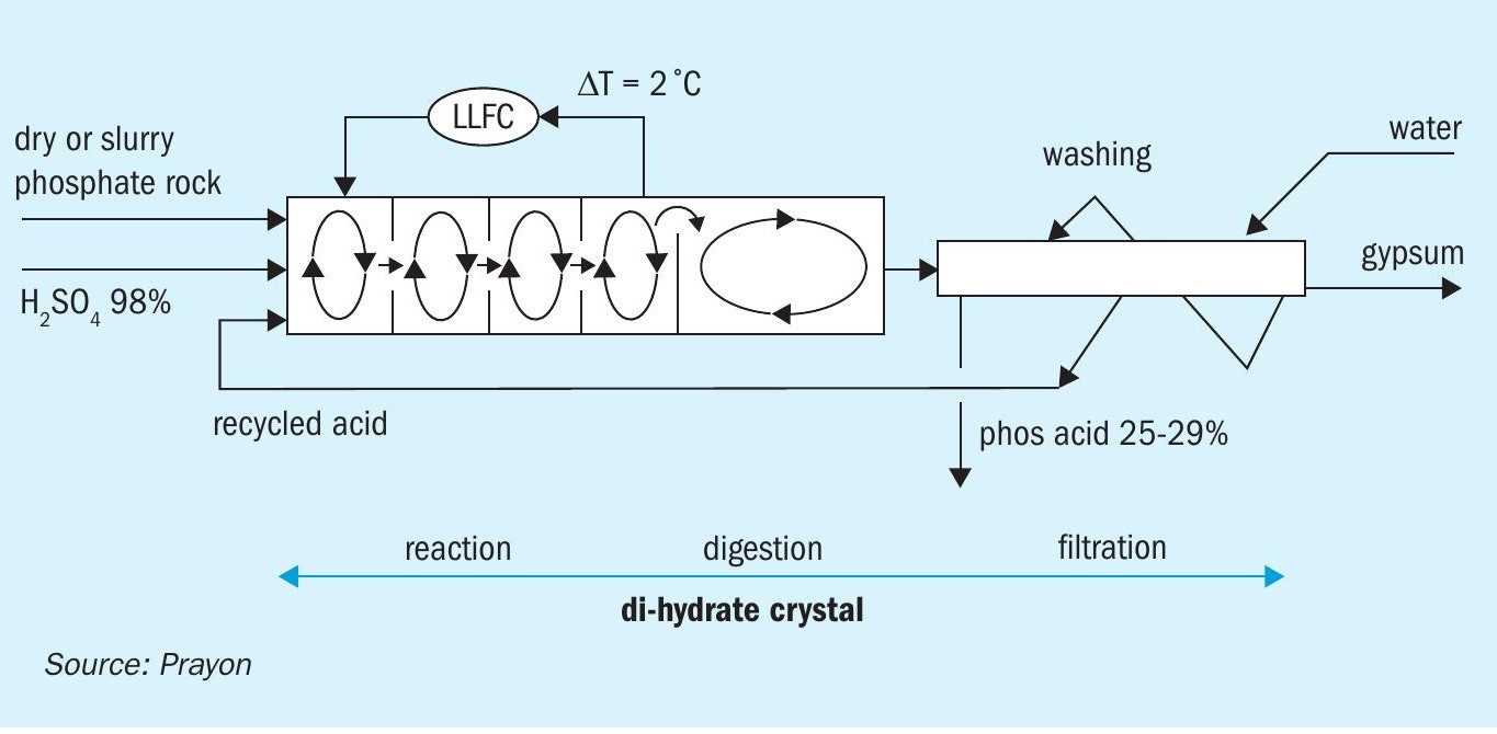
The viability of using a slurry feed requires a closer look at the water balance of a phosphoric acid plant. Process water mainly enters the phosphoric acid production process via the filter as gypsum cake washing water and is then recycled back to the reactor (see Figure 3 for a typical DH process). Water also leaves the reaction-filtration section:
- With the filtrate as weak phosphoric acid
- With the phosphogypsum as crystalline and free water
- As water vapour to the stack via the scrubber
- As water vapour via the flash cooler condenser to the cooling tower.
Phosphoric acid production processes (see Table 1) that generate hemihydrate gypsum (CaSO 4 . 1 / 2 H 2 O) produce filtered acid with a higher P 2 O 5 content compared to the DH process that generate standard gypsum (CaSO 4 .2H 2 O). The P 2 O 5 content of filtered or weak acid of the HH process, for example, is around 40-42 percent versus 25-29 percent for the single DH process (Table 1). This is important for the water balance as stronger 42 percent P 2 O 5 HH acid obviously contains less water than weaker 29 percent P 2 O 5 DH acid.
In addition, since hemihydrate contains 1.5 molecules less crystalline water than gypsum, less water will leave the HH process in the form of phosphogypsum waste. Overall, therefore, more water will exit a DH process plant via both the weaker acid and the phosphogypsum waste generated. These higher water losses allow the DH process – the most commonly used phosphoric acid production process globally – to easily accept rock slurry feed as well as dry rock feed.
Phosphate rock that arrives from the mine and beneficiation plant as a slurry is stored in agitated buffer tanks. The agitators maintain a homogeneous suspension to allow upstream pumping of the slurry to the reactor.
The solids concentration of the rock slurry arriving on site can be as low as 45-55 percent. This could be pumped directly to the phosphoric acid reactor but is usually partially dewatered to about 63-65 percent solids by using thickeners or centrifuges or a combination of both.
Reducing the quantity of water entering the reactor via the rock slurry is beneficial as its improves subsequent filtration efficiency by allowing greater washing of gypsum on the filter.
The materials used in rotary and static dewatering equipment and piping need to be carefully selected, as these are in contact with high concentrations of abrasive solids. The piping systems also need to be equipped with suitable abrasion resistant valves and flushing lines.
Phosphogypsum
In the reaction section – the heart of the phosphoric pant – sulphuric acid and phosphate rock are reacted together to produce phosphoric acid and phosphogypsum (PG). The PG is separated from the phosphoric acid via filtration using a table filter, belt filter or tilting pan filter.
The PG generated by most plants using a DH or HH single crystal process generally contains too many impurities and needs to be disposed of. Double crystal processes, in contrast, deliver much better quality PG.
PG leaving the filter typically contains 20-25 percent free moisture and can be transported via belt conveyors to a dry PG stack. Alternatively, PG can be mixed with water and pumped to wet PG stack or PG pond to settle, allowing water to be returned and recycled.
Marine outfalls are also permitted in some projects. This involves flushing the PG with seawater into homogenisation tanks for subsequent pumping out to sea. Lime water can also be added to these tanks to neutralise the PG slurry, if specified by local regulations or necessary for downstream applications.
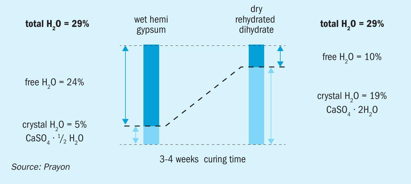
Double-crystal phosphoric acid processes that generate hemihydrate instead of gypsum during the second crystallisation stage, such as the DA-HF or CPP process (Table 1), provide an extra advantage: they generate a self-drying, high quality phosphogypsum by-product. The natural rehydration of hemihydrate (plaster of Paris) into gypsum reduces free moisture from about 20-25 percent to 10 percent over a curing period of 3-4 weeks (Figure 4). After curing and crushing, this self-drying gypsum product can potentially be used in the plasterboard industry or as a cement retardant, depending on the quality of the original phosphate rock.
Acidic cooling tower
Cooling water is needed throughout the phosphoric acid plant at the following sections:
- Reaction flash cooler: Large amounts of heat are generated in reaction tanks by the dilution of sulphuric acid and the exothermic reaction of sulphuric acid and phosphate rock. This is generally removed by either air cooling or evaporative cooling. In the second option, cooling water is used to condense evaporated water in a condenser downstream of the flash cooler.
- Vacuum filter: Gypsum generated in the reaction tanks is separated from weak phosphoric acid on a vacuum filter. Cooling water is used by a condenser downstream of the filter to reduce the amount of water vapour entering the vacuum pump.
- Concentration evaporators: Filtered acid is typically generated at either 25-29 percent P 2 O 5 (dihydrate process) or 40-42 percent P 2 O 5 (hemihydrate process) concentration. This needs to be further concentrated to the required fertilizer-grade or merchant-grade acid (MGA), usually up to 52-54 percent P 2 O 5 . This is achieved by combining a heat exchanger and an evaporator under vacuum in a forced circulation loop. Cooling water is used by a condenser downstream of the loop to condense the evaporated water generated.
Direct contact condensers are widely used downstream of the reaction flash cooler, vacuum filter and concentration evaporators. Cooling water in these condensers is typically acidic (pH <2) as it adsorbs the fluorine present in phosphoric acid when this is released as vapour under vacuum. Consequently, special acid resistant materials are used when designing cooling towers for phosphoric acid plants – and the associated cooling water piping, hot water channels and cold and hot cooling water circulation pumps. Forced draft concrete cooling towers fitted with anti-acid protection are recommended and commonly used.
There are several installation options for cooling water networks at phosphoric acid plants based on channels and/or piping plus vertical or horizontal cold and hot cooling water pumps, as described fully in a previous De Smet Agro article (Fertilizer International 509, p61). The engineering company will always select the cooling water design option that delivers the operational flexibility required by the client while taking account of any layout constraints.
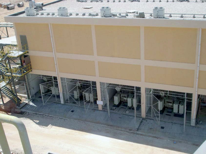
Electrical substation
Electrical power is an important and essential utility at a phosphoric acid plant. The engineering company therefore needs to provide a complete design for an electrical substation that includes:
- High voltage (HV) feeders from the grid
- Medium voltage (MV) and low voltage (LV) transformers
- The MV and LV panels and motor starters.
Heavy oil-type transformers are usually placed on the ground floor of the substation along with the HV switchgears. Bus ducts and LV motor control centre (MCC) panels, in contrast, can be located on a higher floor. A separate room is usually provided at the substation for the battery charger and batteries.
The safety of the substation design is assessed by performing proper short circuit analysis, voltage drop and harmonics calculations and ensuring these meet local regulations. All electrical equipment generates heat and therefore requires cooling. Transformers located outdoors can be cooled by natural ventilation while air conditioning is provided in hot climates for electrical gear installed inside the substation.
The installation of additional emergency power units is included in the substation design if these are required and have been requested by the client.
Merchant grade acid and fluosilicic acid
In plants producing for export, the concentrated phosphoric acid needs to be conditioned to merchant grade acid (MGA), typically at 52-54 percent P 2 O 5 . In many cases, the MGA is cooled down to about 45°C in maturation tanks. Solids content is also reduced – typically from 2-3 percent solids to a maximum of 0.5 percent solids – using clarifiers equipped with a rake and flocculants. The clarified MGA can then be sent to the export storage tanks. The trouble-free and efficient removal of sludges at the bottom of the clarifiers requires special attention.
Storage and loading facilities are also designed for fluosilicic acid (FSA), a by-product of fluorine recovery at phosphoric acid plants. Dedicated loading pumps are designed to safely transfer the MGA or the FSA from their respective export storage tanks to rail or road tankers.
Engineering activities
The engineering company (the licensee) will take the process design package (PDP) developed by the licensor and complete the process design. This includes developing detailed P&IDs (see box), finalising the process description and all of the control-related documents, these including the interlock descriptions, the causes & effects chart, the alarm & interlock list, etc.
Suitable materials are selected for rotating and static equipment, piping, and instruments. These are chosen based on in-house experience, good engineering practise and feedback from major equipment suppliers. Protection for the concrete and steel surfaces in the phosphoric acid plant is provided by selecting acid-resistant brick and rubber linings.
All the above requirements are then set out in detail by the engineering company in datasheets, drawings and high standard specifications. These cover mechanical and electrical equipment, piping, valves and instrumentation.
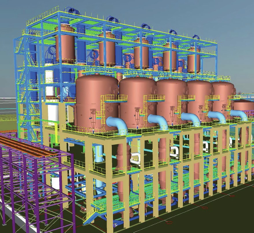
3D-model
The engineering company is responsible for preparing a 3D-model of the phosphoric acid plant. This is based on the production process, as defined by the licensor, while also taking account of the maintenance needs of the client. The following design elements are completely integrated within the 3D-model:
- Civil and steel structural design of the buildings and substation
- Concrete foundation of the storage tanks
- Steel structure supporting the storage tank agitators
- Acidic cooling tower with cooling water basins
- Pipe racks and cable trays.
Phosphoric acid plant operations – as is well known in the industry – are highly maintenance sensitive. The periodic flushing of pipelines, visual inspections and the replacement of worn parts are all necessary. Attention must therefore be given to these maintenance requirements during the early stages of plant design. For example, space needs to be reserved inside and around buildings to allow cleaning and easy maintenance access using manual or motorised hoists and mobile cranes.
The model, by including 3D-drawings from equipment suppliers, can also offer a high level of precision for the connecting piping. Additionally, the model is a helpful tool during HAZOP analysis and the training of plant operators, as it allows virtual walks to be made inside the plant.
The 3D-model is reviewed by the engineering company with the licensor and the client to derive the following: l 3D views from all required angles l 2D plot plan, floor, and section view drawings l Piping isometrics l Material take-off (MTO) for civil & structural elements, all ducts, piping & fittings, electrical & instrumentation wiring cable trays.
Preliminary MTOs, developed at the frontend engineering design (FEED) stage, are used to calculate a robust project capex estimate. While final MTOs, prepared at the end of the engineering phase, are provided to the installation contractors and bulk materials suppliers for supply and construction purposes.
Conclusion
Delivering operationally effective and maintenance-friendly phosphoric acid plants requires a combination of expertise and experience. Having an experienced engineering company (licensee) completing the process design package (PDP) provided by the licensor – and completely engineer the off-site sections and plant utilities – is therefore of prime importance.
As highlighted by this article, the successful and reliable operation of a phosphoric acid plant requires a well-engineered, easy to maintain plant. This includes:
- Well-designed phosphate rock unloading, storage and dosing facilities
- A correctly sized gypsum filtration, storage and disposal system
- The proper selection of acidic cooling water equipment
- A well-matched electrical substation
- Customised loading equipment for end-products.
Author’s note
This article is based on the De Smet Ago presentation by Sébastien Bernard at CRU Phosphates 2024 International Conference & Exhibition, Warsaw, 26-28th February 2024.
PIPING & INSTRUMENTATION DIAGRAMS (P&IDs)
Piping & instrumentation diagrams (P&IDs) are key process documents that are essential for developing the detailed engineering design of the phosphoric acid plant. These are prepared by the engineering company based on the process flow diagrams, mass balance and equipment list provided by the licensor.
The first diagram, usually called the legend P&ID, includes all the standard symbols and abbreviations and tagging for the instrumentation, equipment, electrical motors, valves, pipelines and accessories for the plant’s process and utility lines. A pipeline number, for example, needs to include at least the following information:
- Pipe size in mm or inches
- Abbreviation for the fluid
- Abbreviation for the pipe class
- Presence of insulation and/or tracing
- A unique sequential number.
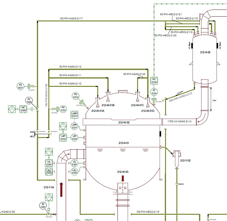
P&IDs cover all the process and utility equipment. They show important information (e.g., pipelines and flow direction, pipeline slope requirements, ducts, control valves and manual valves, instruments, control loops, interlocks, etc) and include vital notes. Two types of notes are usually provided:
- General notes. These are identical notes made on every P&ID. Notes included with the legend P&ID, for example, will explain the symbols and abbreviations used, and indicate what vents and drains are required at each high and low point, respectively, on a pipe.
- Specific notes. These refer to specific actions or precautions that are necessary during installation and particular operations.
The P&IDs are an excellent illustration of the value that an engineering company’s accumulated experience, gained over many years, can bring to detailed engineering design. This knowledge is shown on P&IDs by indicating where mandatory bypasses, flushing lines and sloped lines for solid charged liquids are required, as well as the use of the proper type of valves for specific fluids, etc. As many pipelines run cross several P&IDs, the diagrams need to show which P&ID the pipelines continue onto next.
The P&IDs, together with the process and interlock descriptions, are the most important documents reviewed and discussed during the hazard and operability (HAZOP) analysis by the engineering company, the licensor and client process engineers. HAZOP analysis is carried out during the detailed engineering phase to systematically identify potential process hazards and possible plant operability problems.
Software can extract and generate useful lists from the P&IDs such as the:
- Equipment list
- Pipeline list
- Control valves list
- Manual valves list
- Accessories list
- Instrument list
- Interlock list
Additionally, the P&IDs correlate with the 3D-model to help ensure consistent plant design and engineering.
Once prepared, the P&IDs are crucial working documents for the piping & instrumentation installation contractors. Site inspectors will also check the final installation against the P&IDs and make red mark-ups to show any deviations, these being inevitable due to installation constraints. This marked-up version is later used to prepare the ‘as built’ P&IDs. These final P&IDs are vital documents that are always kept in the control room of the phosphoric acid plant together with the operating manual.