Nitrogen+Syngas 390 Jul-Aug 2024

31 July 2024
How to solve stripper efficiency issues (part 1)


- the carbamate could be recycled at synthesis pressure so no extra water needed to be added to recycle the carbamate;
- a medium pressure recirculation section was no longer needed and;
- with the condensation of strip gases in the high pressure carbamate condenser, low pressure steam could be produced, which could be used in the downstream sections leading to a reduction of the steam consumption of a urea plant by a factor of approximately two.
US patent 3,356,723 describes the invention of the HP CO2 stripper:
“In a continuous process for the preparation of urea wherein NH3 and CO2 are reacted at elevated temperature and pressure to continuously provide an ammonium carbamate melt, thereafter in an autoclave, said melt being converted into a urea solution containing ammonium carbamate and the carbamate being stripped from said solution by decomposing said carbamate into NH3 and CO2 by heat and expelling NH3, CO2 and H2 O from said solution, the improvement which comprises continuously stripping the urea solution with CO2 in a stripping zone outside said autoclave and at a pressure of at least 50 atmospheres up to urea synthesis pressure wherein the urea solution flows downwardly along the inside of externally steam heated tubes in the stripping zone and CO2 stripping gas passes upwardly in said tubes in contact with said urea solution, the pressure of the heating steam being in the range of 15-30 atm., whereby NH3 and CO2 are expelled from said solution, condensing the resulting mixture of CO2 gas and gases expelled from said urea solution after addition of further NH3 and at a pressure of at least 50 atmospheres up to urea synthesis pressure to form a carbamate solution and returning the thus formed carbamate solution to said autoclave for further urea synthesis.”
In the HP CO2 stripper, urea reactor effluent is thus treated counter currently with CO2 in a stripper at high pressure in order to dissociate carbamate and at the same time enable easy condensation of the carbamate gases without the addition of water. Preferably, this is done at the same pressure as the reactor operating pressure. The condensation of strip gases will produce steam leading to a significant reduction in steam consumption to produce urea.
This patent from 1967 has revolutionised urea technology and nowadays all modern urea processes operate an HP stripper.
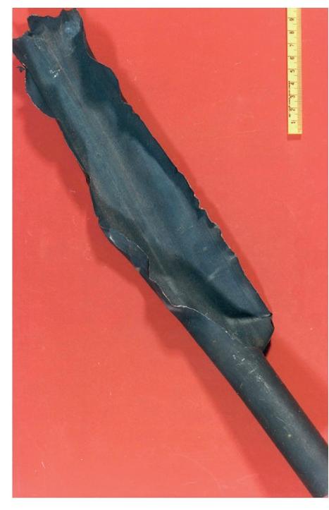
The first stripper (1960s) had tubes made out of 316L Urea Grade but soon after the start-up several tubes ruptured due to high corrosion rates (refer to the picture). It was concluded that this material was not sufficiently resistant to ammonium carbamate corrosion at these severe process conditions in the tubes (high temperatures and low partial pressure of oxygen). A new material, austenitic stainless steel 25-22-2, was developed with a higher chromium content which proved to have much better corrosion resistance and could achieve long lifetimes. The world record has been set by SKW Piesteritz in Germany with a lifetime of 35 years with Sandvik (now Alleima) 2RE69 25-22-2 tubes.
The efficiency of the CO2 HP stripper in Stamicarbon plants is typically around 80% and is a critical process parameter for safe, reliable and efficient operation. This is especially true for austenitic stainless steel tubes as these can experience active corrosion.
There are many causes that can lower stripper efficiency, such as:
1. High liquid load
2. Fouling liquid dividers
3. Bad installation liquid dividers
4. High delta-P range liquid dividers
5. Fouling inside tubes
6. CO2 distributor issues
7. Entrainment of condensate with steam
8. Steam not saturated
9. High N/C ratio of liquid entering stripper
10. Not vertical installation of HP stripper
11. Large size stripper and old design baffles shell side
All of these causes will be discussed in detail in future instalments of Plant Manager+ …