Nitrogen+Syngas 390 Jul-Aug 2024
31 July 2024
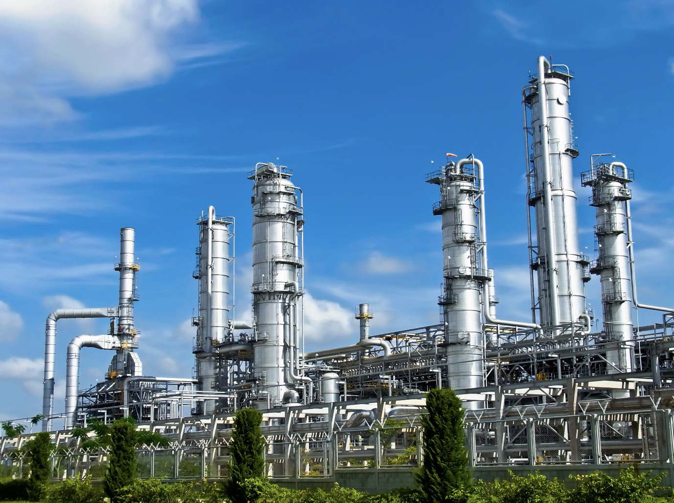
Urea technology showcases
UREA TECHNOLOGY
Urea technology showcases
Casale, Saipem, Staicarbon & Toyo Engineering Corporation showcase a selection of innovative technologies that have recently been brought to the market.
Matteo Fumagalli
Since the 1970s, the ammonia- or self-stripping process has served as an alternative to the CO2-stripping process for industrial urea synthesis, favoured for its competitive energy consumption and operational costs. The CO2-stripping process decomposes carbamate at synthesis pressure using CO2, whereas the self-stripping process relies on heating, leading to excess ammonia in the urea solution, necessitating purification at medium pressure.
Initially seen as more complex compared to CO2 -stripping, the efficient steam consumption and ease of operation determined the success of the self-stripping process. A major advancement in steam consumption was achieved implementing heat recovery from medium-pressure carbamate vapours. Soon recognised as essential for improving efficiency, this heat integration became standard in new and revamped plants since the 1990s. However, no significant improvements have been made for years, seemingly reaching an energy optimisation plateau.
Casale developed an improved self-stripping process to further reduce medium-pressure steam and cooling water needs. The main innovation is an additional carbamate decomposition step before the conventional medium-pressure section, allowing heat recovery to be extended, reducing the need for LP steam and cooling water.
The advantages of the self-stripping process include its horizontal layout, smaller high-pressure equipment, reliable operation, and excellent energy performance. However, it also has drawbacks like dual-pressure purification stages, separate ammonia recovery, and the need for noble materials in the HP stripper.
Modern CO2-stripping processes include a medium-pressure purification stage in their flow sheets since it is recognised as a key feature to lower the MP steam consumption. Conversely, the traditional self-stripping process appears to have hit an energy efficiency limit. Improving the self-stripping efficiency involves reducing MP steam consumption in the HP stripper without destabilising the steam network. This is possible only by increasing the extent of heat recovery which must nearly double to compete with the best CO2-stripping processes.
HYPER-U process
HYPER-U is a self-stripping process with innovative peculiarities. Among others, the most distinctive are “hybrid-stripping” and the “combi-reactor”. In the conventional self-stripping process, the HP stripper is a thermal decomposer, in HYPER-U a minor portion of CO2 is fed to the HP stripper to reduce free ammonia in the urea solution leaving the HP section. This drastically reduces the amount of ammonia to be recovered at medium-pressure and allows carbamate vapour condensation along a higher temperature profile which favours deep heat recovery. This hybrid approach blends the best aspects of both CO2-stripping and self-stripping processes, resulting in higher efficiency.
Vapours from the HP stripper are partially condensed in a kettle-type heat exchanger generating steam at 5.0 to 6.0 barg, but most of the condensation occurs in a “combi-reactor”. The combi-reactor is a vertical vessel comprising a tube bundle and trays which makes it an actual combined vertical HP condenser-reactor. The volume of the combi-reactor is sufficiently large to ensure an adequate residence time to initiate the conversion of CO2 into urea. The excess heat of carbamate condensation is removed with direct process-process heat transfer; namely, the heat released by condensing high-pressure carbamate vapours is used for carbamate decomposition at 30 barg. A simplified flowsheet of the high-pressure loop of HYPER-U is shown in Fig. 1.

A critical aspect of the HYPER-U process is indeed the inclusion of an extra carbamate decomposition stage. The urea solution from the HP stripper is first expanded to 30 barg and fed to the tube bundle (tube side) inserted in the combi-reactor. Direct process to process heat exchange, not relying on an intermediate utility stream, allows carbamate to be decomposed more effectively even at 30 barg. Following the 30 barg purification stage, urea solution is then fed to the conventional medium-pressure sections for final purification.
The final carbamate decomposition stage at 3.5 barg also adopts an innovative concept. Instead of a shell-andtube exchanger which adopts LP steam to heat up the urea solution, carbamate decomposition occurs in a column with a packed bed. The heat of reaction is provided by process vapours from the waste water treatment (WWT) section. This represents a direct heat integration since the heat of condensation of the water in the WWT vapours is used for carbamate decomposition. Using WWT vapours for LP carbamate decomposition has another major advantage: several pieces of equipment normally present for this service, such as the LP decomposer bundle, steam drum, WWT reflux condenser with its tempered water loop and carbamate reflux pumps, can be avoided.
Urea solution concentration to 96.599.7 wt-%, depending on the product finishing technology, is carried out in a single or double vacuum evaporation section. The first stage evaporator employs as heat source carbamate vapours at 30 and 18 barg respectively from the medium-high and medium-pressure carbamate decomposers. The condensation curve of the 30 barg vapours follow a temperature profile higher than the conventional MP vapours which allows the urea solution to be concentrated up to 95% using only heat recovered from process streams without relying on steam. Compared to the conventional self-stripping process, where MP carbamate vapours are used to concentrate the urea solution typically up to 84-85 wt-%, the steam saving attained in HYPER-U is 60% higher. A simplified flowsheet of the purification and concentration sections of HYPER-U is shown in Fig. 2.

The heat integration strategy also foresees the traditional ammonia pre-heating step utilising the heat of condensation of the low-pressure carbamate vapours. HYPER-U also features an intrinsic carbamate pre-heating; carbamate recovery downstream of the HP loop occurs at 110-115 °C which is made possible by the operating pressure at 30 barg. With respect to the conventional self-stripping process, where carbamate solution is recovered at 80-85°C, the higher temperature causes an increase of steam production in the HP carbamate condenser of approximately 40 kg/tonne.
Steam and cooling water saving strategy
The overall heat integration strategy of HYPER-U is intended to maximise the use of process heat sources to replace where possible the use of low-pressure steam. Using 30 barg carbamate vapours, condensing along an elevated temperature profile, makes it possible to exploit their enthalpy to an extent not possible in the conventional self-stripping process. As a result of this innovative heat integration and the other heat recovery stages, the overall steam demand for urea purification and concentration is drastically reduced.
A lower demand of steam in the downstream plant sections opens up the possibility to limit the duty of the HP stripper without upsetting the steam network. Lower medium-pressure steam consumed in the HP stripper, de facto leads to less 5.0 barg steam produced in the HP carbamate condenser. In order to keep a balance between LP steam demand and production, it is paramount to minimise the demand for purification and concentration. The heat integration strategy implemented in HYPER-U allows the supply of 20 barg steam to the HP stripper to be limited without the need to make up the 5.0 barg header. The consumption of 20 barg steam of the HP stripper is approximately 20% lower than in the conventional self-stripping processes.
Another significant positive effect of the deep heat recovery strategy implemented in HYPER-U is the drastically lower cooling water consumption. Maximising the amount of heat recovered for process use causes a corresponding reduction of heat normally wasted to cooling water. An overall saving of 14% cooling water can be achieved.
Other advantages
The hybrid-stripping concept has an impact on the size of the HP stripper; in a conventional modern self-stripping process, the temperature within the tubes of the HP stripper follows an approximately linear profile from 189°C at the top to 203-204°C at the bottom. In HYPER-U the bottom temperature is kept at 196-198°C and the duty is 20% lower. Maintaining the same pressure of steam, the required surface area can be decreased accordingly which positively affects the cost of the item.
Also the cost of the ammonia recovery equipment, such as the ammonia condenser and MP absorber, are reduced because of hybrid-stripping, due to the fraction of free ammonia in the urea solution leaving the HP stripper in HYPER-U being 40% lower. The flow rate of ammonia to the HP ammonia pumps is also reduced, by 20%, which is reflected in the cost of the HP ammonia pumps, but also in the overall power consumption.
Conclusions
The HYPER-U process marks a drastic improvement compared to the consolidated self-stripping technology in terms of energy performance. Among the most relevant features are the hybrid design of the HP stripper which employs a minor stream of CO2 to lower the free ammonia and the combi-reactor, a submerged HP carbamate condenser combined with a reaction vessel. The combi-reactor enables a direct process-process heat exchange used to decompose carbamate at 30 barg. These two peculiarities allow an efficient heat integration strategy in the purification sections resulting in reduced demand of LP steam. Consequently, the duty of the HP stripper is reduced by 20% compared to state-ofthe-art self-stripping processes as is the consumption of MP steam extracted from the CO2 compressor turbine.
The thorough heat recovery carried out in the carbamate recovery section also reduces the consumption of cooling water by 15% with consequent benefit in terms of raw water make-up and electricity absorbed by cooling towers and pumps.
The overall performance of the HYPER-U process makes it competitive with all urea processes currently available, either based on self-stripping or CO2 stripping technology. Moreover, the excellent energy performance is not obtained at the expense of augmented capex due to fewer and smaller pieces of equipment.
………………………………………………………………………………………………………………………………………………………………………………………………….
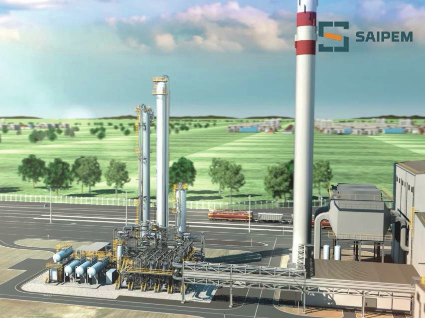
SAIPEM SpA
Compact urea plant for green hydrogen and CO2 valorisation
As the world moves towards tackling climate change, there is a surge in renewable energy installations worldwide. The progressive reduction in cost of renewable energy will lead to a new revolution in green chemistry applications. Technical advancements and environmental restrictions are also giving impetus to the development of CO2 capture solutions.
In this scenario of worldwide change Saipem as owner and licensor of the Snamprogetti™ Urea Technology has developed a modularised solution for small-scale urea plants which fits perfectly with the portfolio of green technologies and CO2 capture solutions that Saipem has developed and secured.
Small scale urea plant by Saipem
Applying decades of experience in licensing, engineering and construction of urea plants having capacities ranging from 300 to 4,000+ t/d, Saipem has re-thought its proven process scheme for applications up to 100 t/d of urea.
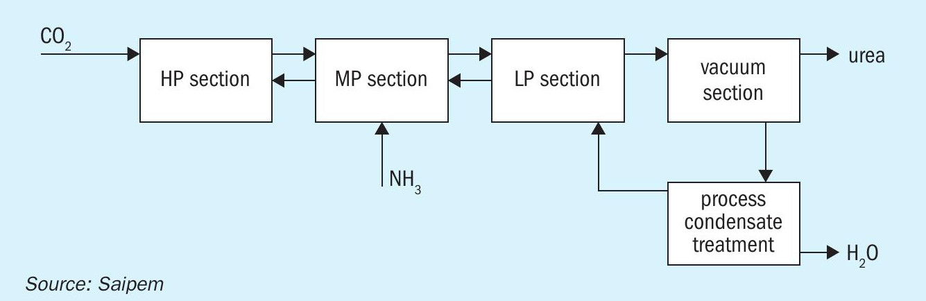
The Snamprogetti™ urea process is renowned and recognised by users worldwide for its operating flexibility, hence the first aim was to extend such flexibility to the small plant; to do so, the classic configuration with its five sections at decreasing pressure have been maintained (Fig. 1).
However, by decreasing the plant capacity, thus moving against the economy of scale, the capital investment is another important factor to be considered during the design. To minimise the time from first production to the break-even point, in a context where energy comes from renewable sources, it was decided to optimise energy recovery along the process scheme thus reducing the number of costly items.
Due to the presence of buffer volumes and the peculiarity of Snamprogetti™ urea technology being able to keep the HP bottled in for up to 48 hours, another approach applied to minimise overall bulk quantities was, e.g., for pumps, to consider installation of a single item with a second identical item kept as spare, stored in a warehouse.
These optimisations to the process scheme and approach to number of installed items, also help to reduce the plant footprint. The scheme fits perfectly with a modularised approach even though it is also applicable for a stick built construction.
Two options have been foreseen for the modular approach. The first option foresees multiple small modules, with module size and weight limited in consideration of possible limitations on road transportation. The configuration modules shown in Fig. 2 have dimensions as per Table 1.


In the second option (Fig. 3) a single module in a configuration that could be easily transported by ship and installed near the seashore is considered.

For a small scale plant it is extremely important to push the conversion in the reactor as much as possible, because a higher conversion in the reactor has the direct consequence of minimising the recycles within the plant (with benefits on overall consumptions) as well as minimising the equipment dimensions.
SuperCups, as demonstrated in different plants worldwide, are the selected solution for boosting the conversion to urea.
Due to the small capacity these plants may fit with DEF production or in general with the production of technical urea for specific applications.
In terms of finishing, the small scale urea plant can be coupled with a traditional prilling tower or a granulation plant, but the choice also extends to a pastillation unit which fits perfectly with the limited production capacity and with low capital investment also providing easy implementation in the modularisation case.
Green feedstocks
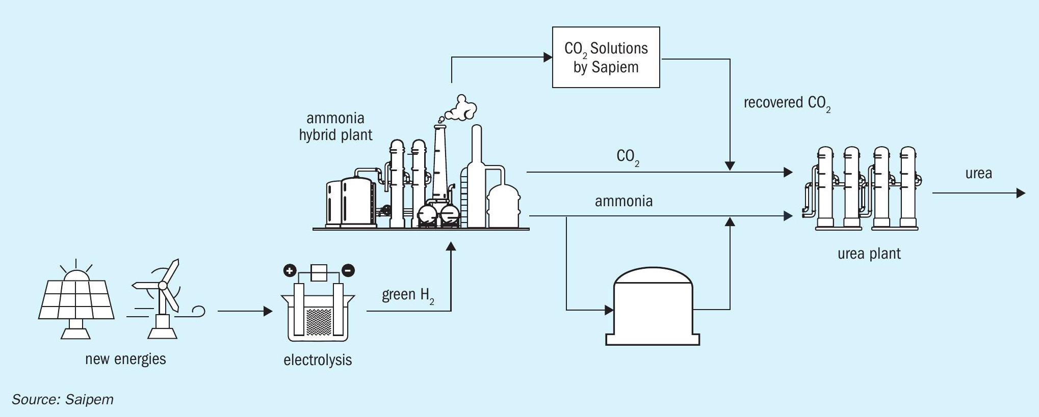
Small scale urea plants per se can be part of a complex with a traditional scheme but, due to their reduced production capacity, they are best suited to valorise waste streams (e.g., of carbon dioxide), extra production (e.g., of ammonia) and/or the availability of renewable energy, thus becoming part of a complex with a sustainable scheme (see Fig. 4).

BLUENZYME™ , the sustainable solution to capture CO2
Post-combustion carbon capture technologies are going to be a key enabler for the effective application of green urea production. In this context, the carbon capture process technologies should yield low-cost, low-complexity operations, solving contemporary problems without creating new ones, while being sturdy under harsh post-combustion oxidising conditions.
Saipem has developed an enzymatic carbon capture technology, CO2 Solutions, consisting of an innovative process that uses a non-toxic, non-volatile solvent, based on potassium carbonate, and promoted by enzymes. Contrary to conventional carbon-capture technologies, the CO2 Solutions process neither requires nor produces toxic products. It is clean and harmless to human health and the environment, with fast absorption kinetics. Furthermore, the low-temperature regeneration allows residual heat to be used to drive the capture and reduce opex.

In addition, to further reduce the impacts related to carbon capture installations, Saipem has developed innovative solutions based on the application of rotating packing beds (RPB). These items boost the mass transfer thanks to the liquid-gas contact enhanced through the centrifugal effect. The RPB pilot plant has been successfully tested and prototypes are under development, targeting the commercialisation of the carbon capture scheme implementing RPBs instead of columns, hence drastically reducing the relevant cost and visual impact.
Thanks to its wide expertise as EPC contractor, Saipem developed BLUENZYME™ , an industrialised solution line consisting of pre-engineered packages based on the application of the above-mentioned enzymatic proprietary carbon capture technology, and designed to be replicable and modular.
Capitalising the technological features of CO2 Solutions, BLUENZYME™ can be effectively integrated into the host plant, even through the implementation of optimised energy balance. In particular, the capability of regenerating the solvent at low temperature allows the reuse of low-grade waste heat streams, the efficient application of heat pumps, as well as the exploitation of natural heat sources like geothermal, minimising the carbon footprint of related installations.
Developed as a plug-and-play concept unit, BLUENZYME™ is capable of capturing CO2 from a post-combustion flue gas, with a reduced execution schedule, by relying on a dedicated and already engaged supply chain for long delivery items.
The construction and installation scheme minimises site work with fast module hook-up and minimal underground work. The module design specifications are compatible with truck transportation for reduced installation costs and easier logistics.
Green urea from green hydrogen production
Urea production is not choosy when it comes to ammonia feed: ammonia could be from existing facilities where there could be extra production, from storage (e.g., in case of seasonal CO2 availability), or from green ammonia plants.
Green ammonia plants are based on the conventional Haber-Bosch process which has been used for decades in the conventional ammonia industry. The main differentiators are the use of water electrolysis instead of hydrocarbon reforming/partial oxidation to generate hydrogen (while nitrogen is produced with standard air separation technologies such as cryogenic distillation or PSA) and the intermittency of renewable power production which implies solutions ensuring smooth operation of the ammonia plants: based on specific project needs, batteries or hydrogen storage are applied or alternatively the ammonia synthesis loop is designed to operate in dynamic mode, following the fluctuations of hydrogen production.
To meet green hydrogen market needs Saipem has developed a pre-engineered, modular, and scalable industrialised solution to be offered with defined and competitive time and costs, for powerto-gas hydrogen, based on the alkaline technology of a key electrolyser OEM, and using a replicable manufacturing approach, to achieve optimised capex/opex.
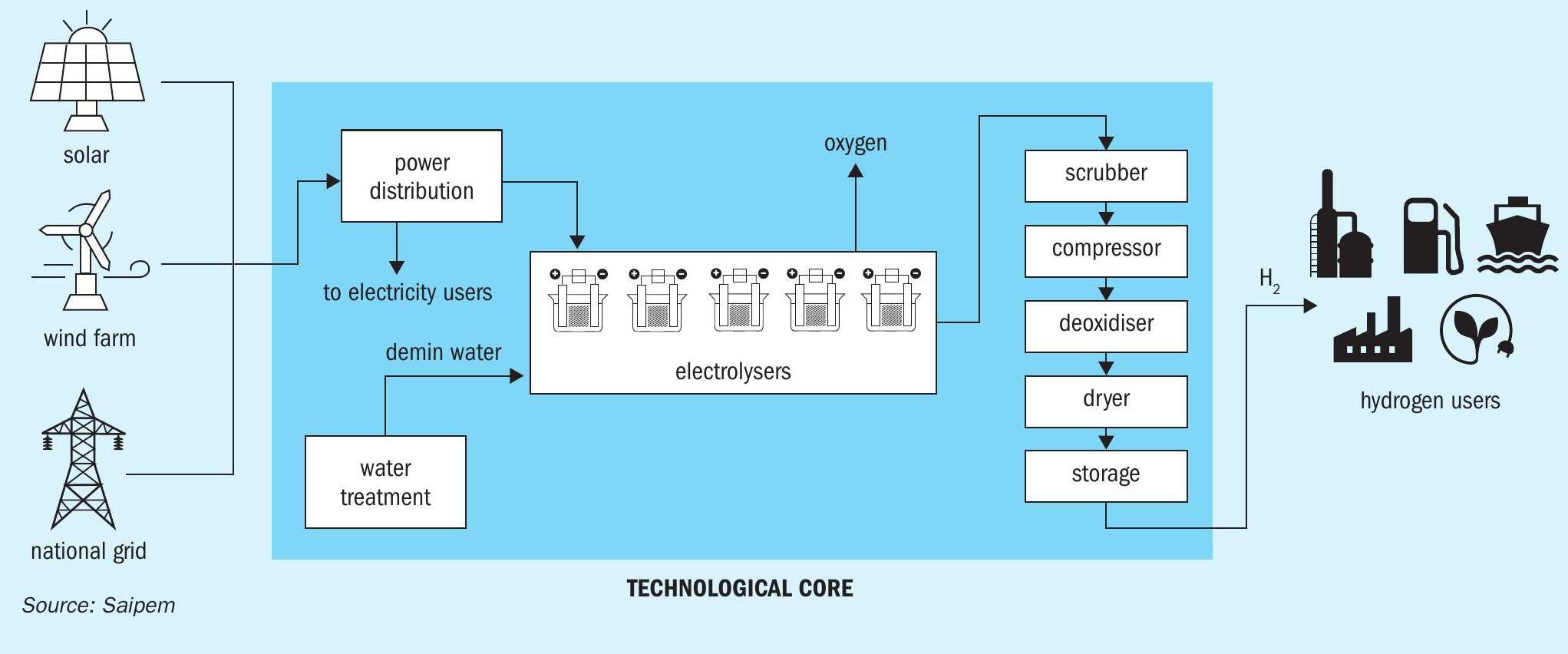

The power from renewable sources (or grid) prior to being fed to the modules is transformed and rectified. Transformers supply incoming AC voltage to the required input voltage for the rectifiers and rectifiers convert AC voltage to DC voltage using IGBT or Thyristor technology.
Each module consists of multiple stacks fed by power and water which is split into hydrogen and oxygen and separated from the electrolyte; the water consumed in the electrolyser is replenished to ensure continuous operation.
At the electrolyser outlet hydrogen is compressed and, since it contains impurities, is subject to a sequence of treatments for purification, mainly deoxidation and dehydration.
Hydrogen is finally sent to the network or to the downstream plant and part of it may be stored. Delivery pressure and storage facilities can be customised according to downstream requirements.
Transportation and storage
Saipem can leverage on the EPC execution of more than 130,000 km of pipelines and the expertise gained in the development of engineering with supercritical CO2, gaseous hydrogen and liquid ammonia.
In addition to the long experience in executing ammonia-urea complexes as EPC contractor, Saipem has proven in-house engineering capability to autonomously design and build ammonia storage tanks.
As the world moves towards tackling climate change, Saipem can provide technologies and expertise to boost and decarbonise existing facilities, to realise sustainable plants by recovering CO2, by exploiting renewable energies to produce hydrogen and subsequently ammonia and urea at a suitable scale with time to market solutions.
A small scale urea plant has been developed by Saipem applying all its knowledge acquired so far to ensure flexibility of operation and limited cost of investment.
Saipem can also be the partner of choice for the set-up of the whole production chain from renewable energy, through CO2 transportation, to product handling, storage and shipping.
References
STAMICARBON
Less steam, more urea

The global fertilizer industry is being reshaped by some of the most critical challenges of recent years. From global energy disruptions to the growing urgency of addressing climate change and transitioning to a lower-carbon economy, the nitrogen fertilizer market is one of the sectors most impacted. As the industry continuously works to reduce the environmental footprint associated with fertilizer production, the requirements for technological efficiency are growing faster than in the past.
Improving the energy efficiency and sustainability of fertilizer production technology are essential tasks, and the technology provider’s contribution can significantly impact the industry’s environmental footprint using existing technology and materials. Recognising the urgency of these goals, Stamicarbon, the nitrogen technology licensor of MAIRE S.p.A, is dedicated to developing and bringing innovative and efficient technologies to market. As a global leader in urea technology, Stamicarbon has introduced its cutting-edge Ultra-Low Energy (ULE) design, a groundbreaking innovation that significantly enhances the energy efficiency of urea production.
The primary advantage of Stamicarbon’s Ultra-Low Energy design lies in its efficient use of high-pressure steam, which is utilised three times instead of the standard two. This makes the process far more energy-efficient than traditional CO2 stripping methods. This article will explore the technology’s features and how it’s setting new benchmarks for energy savings in the industry, demonstrating its potential to lead the way in more sustainable fertilizer production.
From one to three
The first conventional total recycle urea plants, designed in the 1950s and 1960s, had hardly any heat integration in the process flow scheme. These plants had a steam consumption of about 1.8 tonnes of steam per tonne of urea, which is very high by today’s standards, and typically had high-pressure (HP), medium-pressure (MP), and low-pressure (LP) recirculation stages. Carbamate and ammonia were recycled separately to the urea reactor. The heat supplied to the urea synthesis solution was used only once in these first-generation urea plants. Therefore, these types of processes are referred to as N=1 processes.
In the 1960s, Stamicarbon introduced its CO2 stripping process, which eventually became the industry standard. The main feature of this process was that CO2 and heat were used to recycle most of the unconverted CO2 and ammonia via the gas phase. The invention of the stripping process was a major milestone in the history of urea production process development. The stripping plants employed the idea of low-pressure steam generation by recovering heat through a high-pressure carbamate condenser. These stripping plants were more energy-efficient than the usual total recycle plants. This process was called the N=2 process because the heat supplied to the high-pressure stripper was recovered in the high-pressure carbamate condenser and utilised elsewhere in the urea plant, such as in the evaporation and wastewater treatment sections, effectively using the heat two times. The average energy consumption of the stripping process is 0.8-1.0 tonne of steam per tonne of urea.
Stamicarbon’s next revolutionary advancement in urea production was the invention of the pool condensation technology. For smaller capacities, the reactor and the HP carbamate condenser were combined into a single piece of equipment, called the pool reactor design. For large-capacity plants, a pool condenser is combined with a vertical reactor, offering a larger reaction volume. Since its introduction, this N=2 process design has been widely adopted by the industry, and Stamicarbon has been focusing on further reducing both operating and investment costs.
With the rising cost of energy, Stamicarbon took on the challenge of significantly reducing steam consumption. This effort led to the invention of the Ultra-Low Energy design, also part of the Launch Melt™ series, where the heat supplied in the form of steam is used three times. This advanced heat recovery scheme results in a reduction in steam consumption and a decrease in cooling water use, making the process far more energy-efficient than traditional CO2 stripping methods.
New industry standard
The primary technological advancement of this process, which leads to significant energy savings, is the use of steam heat three times within the design. A medium-pressure recirculation section (MP section) is required to reuse this heat twice. This is achieved by arranging the carbamate to be flashed at medium pressure and reheated using the heat of reaction and condensation. The reheated carbamate is then used for heat recovery, specifically for evaporation, as shown in Fig. 1.

As a result, steam consumption can be reduced by up to 40%, and cooling water consumption can be reduced by about 16% compared to traditional CO2 stripping processes. This process configuration achieves an impressively low steam consumption of less than 560 kg per tonne of urea, compared to approximately 870 kg per tonne in conventional urea processes.
The process configuration
The configuration of the process is shown in Fig. 2. The overall configuration of this design consists of a high-pressure stripper, an Ultra-Low Energy pool reactor or an Ultra-Low Energy pool condenser with a vertical reactor. The main change is that the Ultra-Low Energy pool reactor now contains two separate U-tube bundles in the shell. One bundle is for generating low-pressure steam as is commonly done in Stamicarbon’s pool condenser and pool reactor plants. The second bundle is used for the heat integration with the MP recirculation section.
The first time the steam is used as a heating agent to obtain high stripping efficiencies in the high-pressure stripper. Subsequently, the heat is recovered by condensing the strip gas in the high-pressure carbamate condenser, pool condenser or pool reactor in the synthesis section to produce low-pressure steam that is used in the sections downstream.
As can be seen in Fig. 2, the urea/carbamate solution is flashed to a medium-pressure separator after leaving the stripper. The urea solution leaving the medium-pressure flash tank is heated inside the second tube bundle of the pool reactor, effectively reusing the heat inside the pool reactor the second time.
On the shell side of the carbamate bundle, condensation of strip gas releases heat (at about 144 bara and 175ºC), which is used to decompose carbamate into ammonia and carbon dioxide at the tube side. Consequently, the tube side of this tube bundle in the pool reactor functions as a medium-pressure rectifying heater. By integrating these two functions, without any intermediate heat transfer medium, the available temperature difference between both process sides allows the bundle to be relatively small.
As illustrated in Fig. 2, the synthesis of the technology includes only two high-pressure pieces of equipment: a high-pressure stripper and a high-pressure pool reactor. Since the gases from the synthesis section can be used in the MP section, the high-pressure scrubber is not needed. This allows for optimisation of the Ultra-Low Energy design’s capex.

In Stamicarbon’s pool reactor design, the total height of the high-pressure equipment structure is limited to about 20 m, where the heaviest piece of equipment, the pool reactor, is located. The stripper is located close to ground level. As the high-pressure scrubber is not part of the design, this results in the lower height of the structure. The vessel at the highest elevation in the plant is the first medium-pressure separator.
Additionally, milder stripper conditions extend the stripper’s lifespan and reduce biuret formation, thereby enhancing the quality of the final product.
More efficiency with Stami Digital
The ease of operation is another benefit of the Ultra-Low Energy design compared to traditional plants. The presence of the medium-pressure recirculation section with the carbamate bundle mitigates disturbances that typically occur in traditional CO2 stripping plants, which arise from discharging liquid directly from the stripper operation to the low-pressure section. To improve the safety and efficiency of the plant’s operation even further, operators should be trained and prepared for various scenarios.
Stamicarbon’s high-fidelity training simulator, part of Stami Digital suite, offers significant advantages to any urea plant. Its unique thermodynamic and kinetic models enable personnel to receive comprehensive training on the urea process and its dynamic behaviour, including standard operating procedures like normal operation, start-up, blocking-in, restarting, and draining. As part of the training program, the model can simulate upsets in the plant, allowing operators to practice responding to upset conditions and bringing the plant back to normal operation.
The training simulator can be configured to replicate an Ultra-Low Energy urea plant precisely. This can include process equipment, control, and interlocking systems, with a corresponding DCS interface that mimics the look and feel of an actual operator’s room. Additionally, it prepares operating staff to run the plant at maximum capacity while minimising specific steam consumption and ammonia losses and allows for testing new or modified operating procedures before implementation. This increased staff knowledge and experience leads to safer and more stable plant operations. It also helps to reduce startup time.
Start-up experience
The urea plant at Jinjiang Xinlianxin, with a capacity of 2,334 t/d, was the first facility to utilise Ultra-Low Energy technology. It successfully started up in February 2021. Prior to start-up, the plant staff was thoroughly trained by Stamicarbon using its operator training simulator to ensure a comprehensive understanding of the expected reactor and plant behaviour. The start-up went very smoothly without any issues from the first attempt. Initially, the plant operated at a turndown capacity. After securing the feedstocks, the plant’s capacity was increased to over 100% within the first week of operation.
The performance parameters at an average plant operation capacity of 102% demonstrate that the Ultra-Low Energy concept is a significant advancement in urea technology (Table 1). The actual high-pressure steam consumption (23 bara, 330 °C) is 567 kg/t urea, which is even lower than the initially expected value during design. This is anticipated to be further reduced by about 20 to 25 kg/t urea through optimisation of the ammonia feed temperature to the synthesis.

Compared to traditional pool condenser and pool reactor designs, this Ultra-Low Energy design plant has proven to reduce steam consumption by about 35% and cooling water consumption by about 16%.
The successful commissioning and stable operation of the plant also validated the mechanical design of the Ultra-Low Energy pool reactor. The design fully utilises the superior corrosion-resistant materials developed by Stamicarbon. The tube bundles and the internals of the distribution box are accessible through the manway by opening the internal covers, enabling non-destructive testing and inspection without restrictions and without the need to dismantle heavy parts.
Optimising conventional plant performance
Most of today’s urea plants can be revamped using the Ultra-Low Energy design concept. Each project is unique, so a combination of these technology components can be selected to meet the specific goals of a plant, delivering distinct performance improvements and benefits.
The Ultra-Low Energy design can significantly increase urea production while keeping the flow rate of extraction steam unchanged. A possible revamp approach includes several steps. First, an existing HP carbamate condenser can be substituted with a double-bundle pool condenser or pool reactor, factoring in the additional reaction volume required for the increased capacity. Second, installing a modified Stamicarbon capacity add-on, which features an MP section with an MP stripper and a flash tank needed to recycle urea solution from the HP stripper to the second bundle of the pool reactor/condenser. Third, installing a modified first-stage evaporator with construction materials suitable to handle carbamate on the shell side. Finally, an economical MP CO2 compressor can be installed to feed CO2 at medium pressure to the MP stripper.
Combining these steps based on a plant’s specifications can reduce steam consumption to levels close to those of the Ultra-Low Energy design while significantly increasing the plant’s capacity.
Conclusion
The energy consumption of the Ultra-Low Energy plant is considered a benchmark performance worldwide. The Ultra-Low Energy design retains all the features of Stamicarbon’s pool condenser and pool reactor designs, including reliability, operability, and corrosion resistance. It offers comparable capex while significantly lowering operating expenses.
With three plants already operational and six more in various stages of development, ranging from 1,640 t/d to 3,850 t/d, the ULE design has set new benchmarks for energy savings in the industry, demonstrating Stamicarbon’s lead in efficient fertilizer production.
With Stamicarbon’s extensive experience in full life cycle support to customers worldwide, these technological developments can be applied to new grassroots urea projects and to revamp existing urea plants, regardless of the original technology provider.
…………………………………………………………………………………………………………………………………………………………………………………………………
TOYO ENGINEERING CORPORATION
New process options for mixed fertilizers and green urea
Toyo Engineering Corporation (TOYO), a global leading engineering contractor and urea process licensor, has recently established new proprietary urea technologies. This article reports on two of these: a novel urea mixed fertilizer process and process options for smaller scale green urea plants. A third new technology, the first wet electrostatic precipitator integrated with a dust scrubbing system for ultimate cleanup of granulation/prilling exhaust air, will be featured in the September-October 2024 issue of Nitrogen+Syngas.
Novel urea mixed fertilizer process
In addition to regulations on urea dust in the exhaust from granulation/prilling processes, regulations on ammonia emissions are also becoming stricter. Acid scrubbing is a viable method for ammonia emission abatement, but it results in ammonium salt by-products, which are sometimes not preferred due to their limited marketability and the necessity of additional facilities. Although various processes to avoid producing ammonium salt have been offered, these tend to be very complex. On another front, urea ammonium sulphate (UAS) demand is steadily increasing at a higher pace than single urea, aiming at better crop yields, higher N-efficiency (less N loss), to meet crop species requirements, soil conditions, and seasonal demands. To address these needs, TOYO offers a simpler and more energy-efficient solution, the Novel Urea Mixed Fertilizer Process, which provides multiple benefits and contributes to sustainability of the fertilizer industry.
Process description and features
A schematic process flow diagram for the Novel Urea Mixed Fertilizer Process is shown in Fig. 1.
The urea solution (approximately 70 wt-% urea) from the urea synthesis process, after passing through the urea solution tank, is concentrated in a two-stage process. First, the urea solution is concentrated by a vacuum evaporator. Subsequently, the concentrated urea solution is further concentrated by an atmospheric air-swept evaporator to obtain a highly concentrated urea solution. The highly concentrated urea solution or urea melt is fed to the product forming section (urea granulation and/or prilling). The exhaust air from the air-swept evaporator and granulation/prilling section is washed with aqueous urea solution and sulphuric acid in the dust scrubber, to less than 20 mg-NH3 /Nm³ and 30 mg-urea/ Nm³ respectively. The addition of a wet electrostatic precipitator (WESP) further decreases the urea emission to less than 5 mg-urea/Nm³ (WESP is not shown in Fig. 1). The urea and NH3 contained in the exhaust air are recovered as a urea-ammonium salt aqueous solution (recovery solution after washing). The condensate in the first evaporator is used for make-up water in the scrubber cleaning solution, and urea and NH3 contained in the condensate are recovered together with the recovery solution from the scrubber. The recovered solution is mixed with the concentrated urea solution from the first evaporator to be further concentrated in the air-swept evaporator, then sent to the product forming section where urea-AS mixed granules or prills are produced.
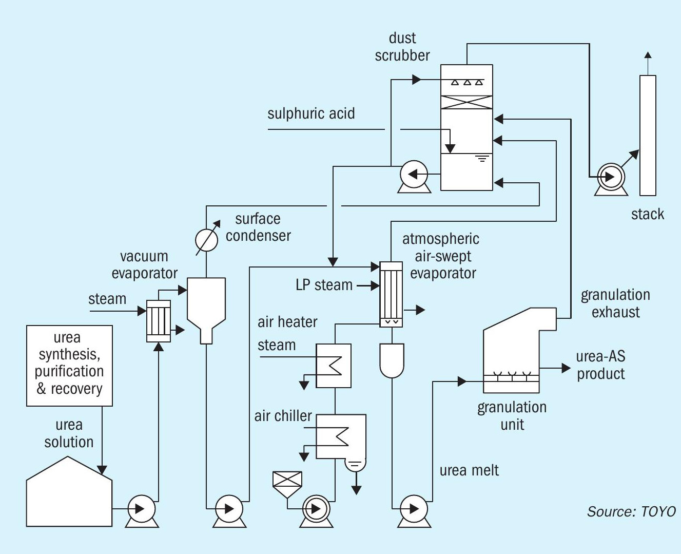
Atmospheric air-swept evaporator
A schematic drawing of the atmospheric air-swept evaporator is shown in Fig. 2.

The atmospheric air-swept evaporator is a liquid falling-film type vertical heat exchanger, heated by steam from the shell side. The urea solution flows down as a thin film on the internal wall of the tube and water rapidly evaporates by contacting counter-currently with dry hot air. This type of evaporator has been traditionally used in conventional urea plants including TOYO process plants, in the so-called “direct prilling process” instead of crystal separation. Although it has been dominated by vacuum evaporation due to several disadvantages, these can be overcome with the Novel Urea Mixed Fertilizer Process as follows:
- Loss of ammonia (derived from ammonia dissolved in feed, biuret formation and urea hydrolysis) and urea (vaporised urea derivatives) entrained with exhaust air – readily solved in combination with acid scrubbing.
- Necessity of additional equipment (air heater, chiller and blower) – common use with granulation unit resolves the problem.
- Relatively complex operation and maintenance (biuret control, deposition of urea derived polymers) – can be appropriately managed thanks to wealth of experience and knowhow in 60 years of operation of TOYO urea plants.
Cost and energy savings
Fig. 3 shows how the Novel Urea Mixed Fertilizer Process (block flow diagram on the right) simplifies the concentration and exhaust air acid-scrubbing system in comparison to the previous vacuum evaporation system (block flow diagram on the left).

The units in blue boxes in the left diagram are eliminated, and the units in red boxes in the right diagram are added. Since the exhaust air from the atmospheric air-swept evaporator is treated directly in the dust scrubber, where it is nearly-saturated with water, it allows for water evaporation instead of condensation. All of the process condensate containing NH3 and urea condensed in the surface condenser for the vacuum evaporator, except for the portion for make-up to the absorbent for the urea synthesis unit, can be used as make-up to the dust scrubber. Thus no excess process condensate containing NH3 and urea is produced, making the whole process condensate treatment system unnecessary, and enabling the process condensate stripper, urea hydrolyser, associated heat exchangers and pumps to be eliminated.
Deletion of the whole process condensate treatment system and second vacuum evaporation system significantly improves the process performance as follows:
- elimination of medium-pressure (25-30 barg) steam for the urea hydrolyser, and low-pressure steam for the process condensate stripper and ejectors for vacuum generation;
- reduction of NH3 and urea recycle from the concentration section to the synthesis section improves the H2O/CO2 ratio in the urea reactor, resulting in higher CO2 conversion.
These improvements provide 5% steam saving in the overall urea process (from raw material supply to product forming) and a 20% capex saving in the concentration section (from 70 wt-% urea solution to melt).
Quality and application of urea-AS mixed fertilizer
Urea fertilizers containing a moderate amount of ammonium salts, especially UAS (from a few percent up to 50% ammonium sulphate), are widely used in Europe and North America. In addition, farmlands of other important regions in the rest of the world, for example, India and South East Asia have also been lacking in sulphate. In these scenarios, the supply of urea-AS fertilizers should be increased, and TOYO’s Novel Urea Mixed Fertilizer Process will contribute to more crop yields by better N-efficiency and by addressing the problem of sulphur-deficient soils. Table 1 shows a typical composition of the urea-AS product produced by TOYO’s Novel Urea Mixed Fertilizer Process. 
Advantages and benefits
As discussed above, “good chemistry” of the atmospheric air-swept evaporator and acid scrubbing provides the following advantages and benefits while achieving NH3 and urea in the scrubber exhaust air of less than 20 mg/Nm3 and 30 mg/Nm3 (5 mg/Nm3 with WESP) respectively:
- no ammonium salt (liquid) by-product because all of the recovered urea-AS solution from the scrubber is concentrated together with the urea solution from the vacuum evaporator in the atmospheric air-swept evaporator, producing urea-AS mixed granules or prills;
- elimination of the entire process condensate treatment section since no excess process condensate is produced in the water-saturated environment of the dust scrubber;
- no ammonium salt contamination to urea synthesis because all ammonium sulphate recovered in the dust scrubber is shipped as urea-AS fertilizer after concentration in the air-swept evaporator;
- flexible urea/AS ratio by adding sulphuric acid and ammonia to the feed stream of the product forming section before the air-swept evaporator;
- acid consumption can be reduced by stripping NH3 in the process condensate from the first evaporator with a condensate stripper (not shown in Fig. 1);
- easy application to existing plants by replacing the existing vacuum evaporator with an atmospheric air-swept evaporator or by adding it downstream of the existing vacuum evaporator;
- better N-efficiency of urea-AS mixed fertilizer;
- all proven process components including air-swept evaporator;
- less capex and opex.
Smaller scale urea plants
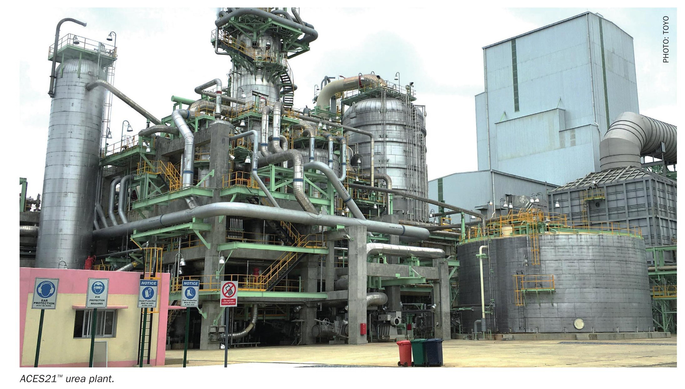
In pursuit of a carbon-neutral society, demand for sustainable urea production utilising renewable resources and non-fossil resources, such as green ammonia, CO2 captured from industrial plant flue gases or DAC (direct air capture), biomass, and municipal solid waste (MSW), is increasing. Green urea plants will be, in many cases, small scale (50-500 t/d) due to constraints in renewable resources and energy. Two process options for green urea are available from TOYO; the scaled-down ACES21® process as an energy saving option and the Advanced Total Recycle Process as a capex saving option.
Scaled-down ACES21® process
The conceptual flow diagram of a scaled-down ACES21® plant is shown in Fig. 4.


The scaled-down ACES21® process is designed to be suited to small to medium scale plants (200 to 2,000+ t/d), adopting a conventional fixed tubesheet vertical heat exchanger to carbamate condenser and a reactor consisting of two partitioned sections. Fig. 5 shows a size comparison of the vertical submerged carbamate condenser (VSCC), carbamate condenser and urea reactor of a 2,000 t/d ACES21® plant compared to a 200 t/d scaled-down ACES21® plant with the following HP equipment features:
- Urea reactor:
- Self-supporting tower without U-tube bundle enables inspection and maintenance inside the reactor even for 200 t/d plant.
- Partition to upper and lower sections for specific N/C ratios realises low-pressure synthesis at 152 barg at high NH3 /CO2 3.7 (same as ACES21® )
- Forced circulation with HP ejector connecting the two sections enables ground level installation.
- Carbamate condenser:
- Fixed tubesheet vertical heat exchanger without internal bore welding (IBW) requires only conventional welding technique for fabrication and maintenance.
- Natural circulation of boiling water in shell side eliminates circulation pumps.
- Application of DP28WTM (super duplex SS by TOYO) to the whole synthesis section eliminates the HP scrubber thanks to a drastic reduction of passivation air requirement.
Advanced Total Recycle Process
The Advanced Total Recycle Process is designed to be suited to small scale plants (200 to 500 t/d) that meet the latest product quality and environmental requirements by applying advanced modern technologies. The DP28W™ urea reactor equipped with TOYO proprietary baffle plates achieves high CO2 conversion (70% at N/C 4.0) at milder conditions (196 barg, 192 °C) than conventional total recycle processes. Fig. 6 shows the overall process flow diagram.

Either vacuum evaporation or crystal separation can be selected for the concentration process. A Vibropriller, which produces excellent uniform prilled urea, can be applied for product forming. Since there is only one item of high-pressure critical equipment (the urea reactor), maintenance is easier than for stripping processes. Electrification is easier in a full-green environment with green ammonia and captured CO2 thanks to the requirement for only low-pressure steam as heat source compared to stripping processes which require medium-pressure steam.
Process performance and economics
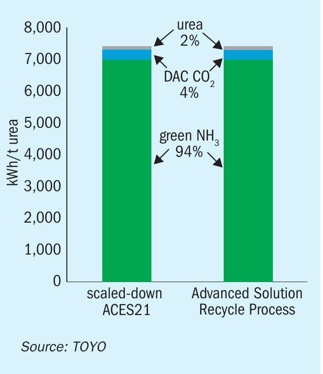
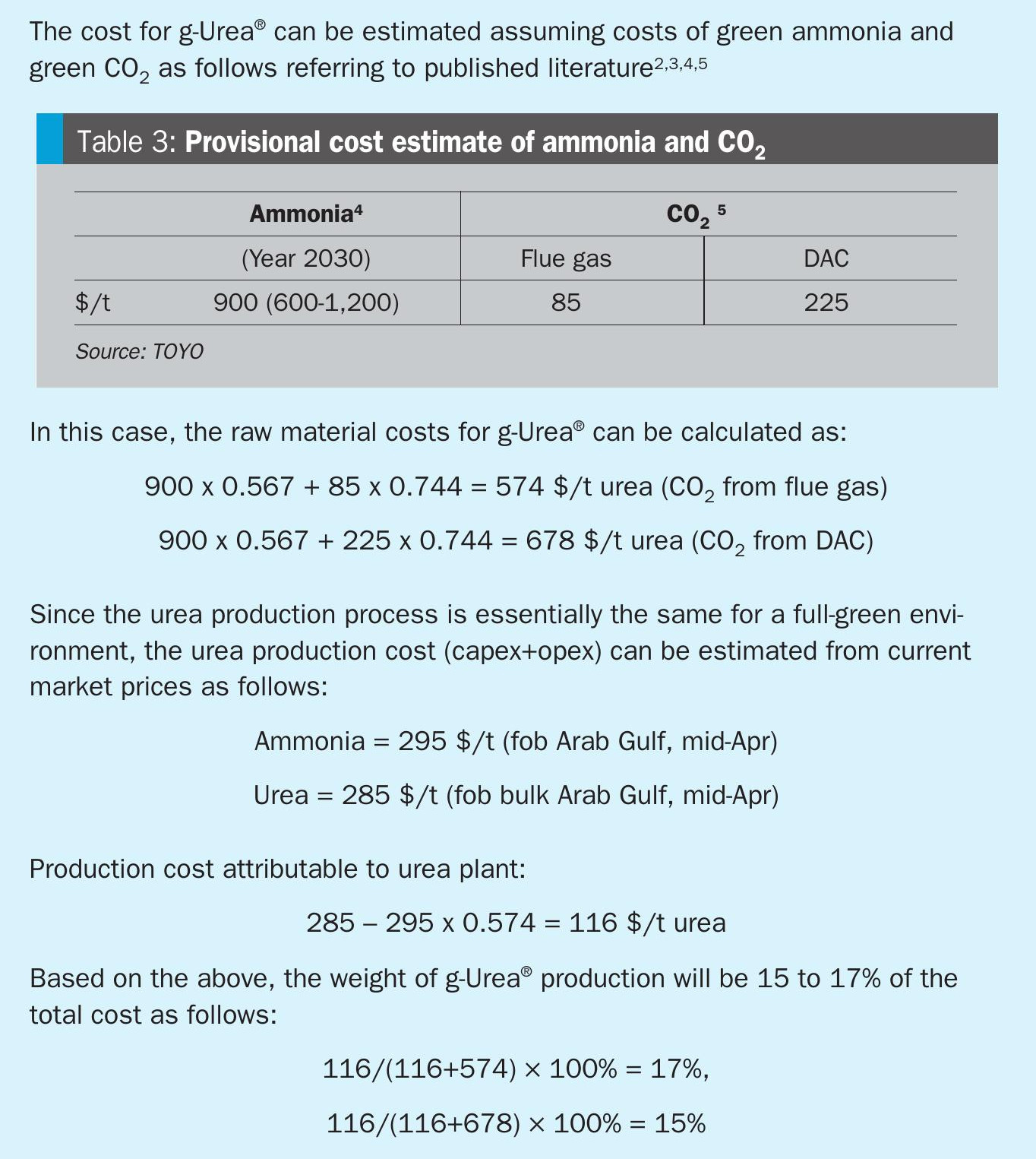
Full green urea production (g-Urea® ) from green ammonia and CO2 from flue gas or DAC, consumes significantly more energy (renewable electricity) than that from natural gas. As shown in Table 2, while a urea plant consumes only 117 to 131 kWh/tonne of urea, green ammonia production consumes 7 MWh/tonne of urea (including hydrogen production by water electrolysis), and CO2 capture from flue gas or DAC consumes 25-300 kWh/ tonne of urea, i.e. electricity consumption for production of green ammonia and CO2 from DAC accounts for 94% and 4% respectively, and the rest (only) 2% is for the urea plant (see Fig. 7). Energy and the cost for green hydrogen (to ammonia) production dominate the economics (opex and capex) of nitrogen fertilizers (urea and ammonium nitrate).

As discussed in the box below, the weight of urea capex, opex and energy requirement will be significantly smaller in a “full-green environment” than a fossil-based environment and, for small-scale urea plants, it would be hard to justify devoting the same amount of resources (workforce and fixed expenses) to O&M activities as for large scale plants. The Advanced Total Recycle Process would be a promising solution for g-Urea® as it has only one item of critical high pressure equipment (urea reactor) and is easier to operate owing to the solution recycle system without HP synthesis loop. The g-Urea® concept will also be advantageous in realising an autonomous and maintenance-free urea plant in the near future.
Conclusion
TOYO’s Novel Urea-AS Mixed Fertilizer Process, which combines an atmospheric air-swept evaporator and acid scrubbing, offers multiple solutions and benefits with regard to pollution abatement and high-value added products.
TOYO also offers two new process options to meet the needs for smaller scale urea plants for its g-Urea® concept: scaled-down ACES21® for energy saving and easier maintenance, and the Advanced Solution Recycle Process for capex saving and easier O&M, as well as for autonomous and maintenance-free urea plants in the near future.
References