Nitrogen+Syngas 391 Sep-Oct 2024
30 September 2024
Urea dust scrubbing system with WESP
EMISSIONS CONTROL
Urea dust scrubbing system with WESP
TOYO has recently introduced new proprietary urea technologies to its technology portfolio including a novel dust scrubbing system with integrated wet electrostatic precipitator (WESP) for ultimate clean-up of granulation or prilling exhaust air, to achieve urea dust emissions of less than 5 mg/Nm3 . Takuhiro Minato of Toyo Engineering Corporation explains how the new system works.
Toyo Engineering Corporation (TOYO), a global leading engineering contractor and urea process licensor, has developed water scrubbing technologies for urea plants with high efficiency (<30 mg urea/Nm3 ) and low pressure loss, focusing on the characteristics of urea dust, which dissolves well in water. Since the 1960s more than 50 scrubbing units have been installed for urea plants. However, to meet recent stricter requirements for urea dust, the development of new technologies is required. Emission regulations vary depending on plant site, and currently 5 mg/Nm3 is the most stringent value. TOYO has focused on WESP as a technology that complies with stricter environmental regulations, and can collect very fine particles with high efficiency and low pressure loss. To explore the feasibility of utilising WESP technology, TOYO carried out pilot plant tests, in cooperation with Petro Vietnam Ca Mau Fertilizer Jointstock Company (PVCFC) and AWS Corporation Srl (AWS), using actual exhaust gas from a granulation plant.
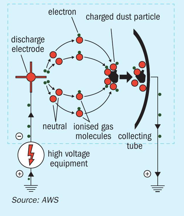
The WESP consists of discharge electrodes and collecting tubes. By applying a high voltage to the discharge electrodes, a potential difference is generated between the discharge electrodes and the collecting surface. Electrons are emitted from the discharge electrodes by corona discharge. The electrons emitted by the corona discharge charge the target fine particles in the gas stream, and the charged particles are separated from the gas stream by adhering to the collecting surface by Coulomb force. Since dust collection performance deteriorates when target particles adhere to collecting tubes and discharge electrodes, periodic washing is necessary. Fig. 1 shows the WESP principle of operation with a collecting tube, which is widely used in WESP. Discharge electrodes are arranged at the centre of the collecting tubes. The equation that represents the WESP dust collection efficiency is known as the Deutsch equation and is expressed as follows.
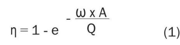
where η = dust collection efficiency, which is represented as η = (Cin -Cout )/Cin , where
Cin = inlet dust concentration (mg/Nm3) and
Cout = outlet dust concentration (mg/Nm3)
A = dust collecting surface (m2)
Q = gas flow rate (m3/s)
ω = migration velocity (m/s), which is the velocity at which target particles move toward collecting tubes and is an important parameter in the sizing of a WESP system.
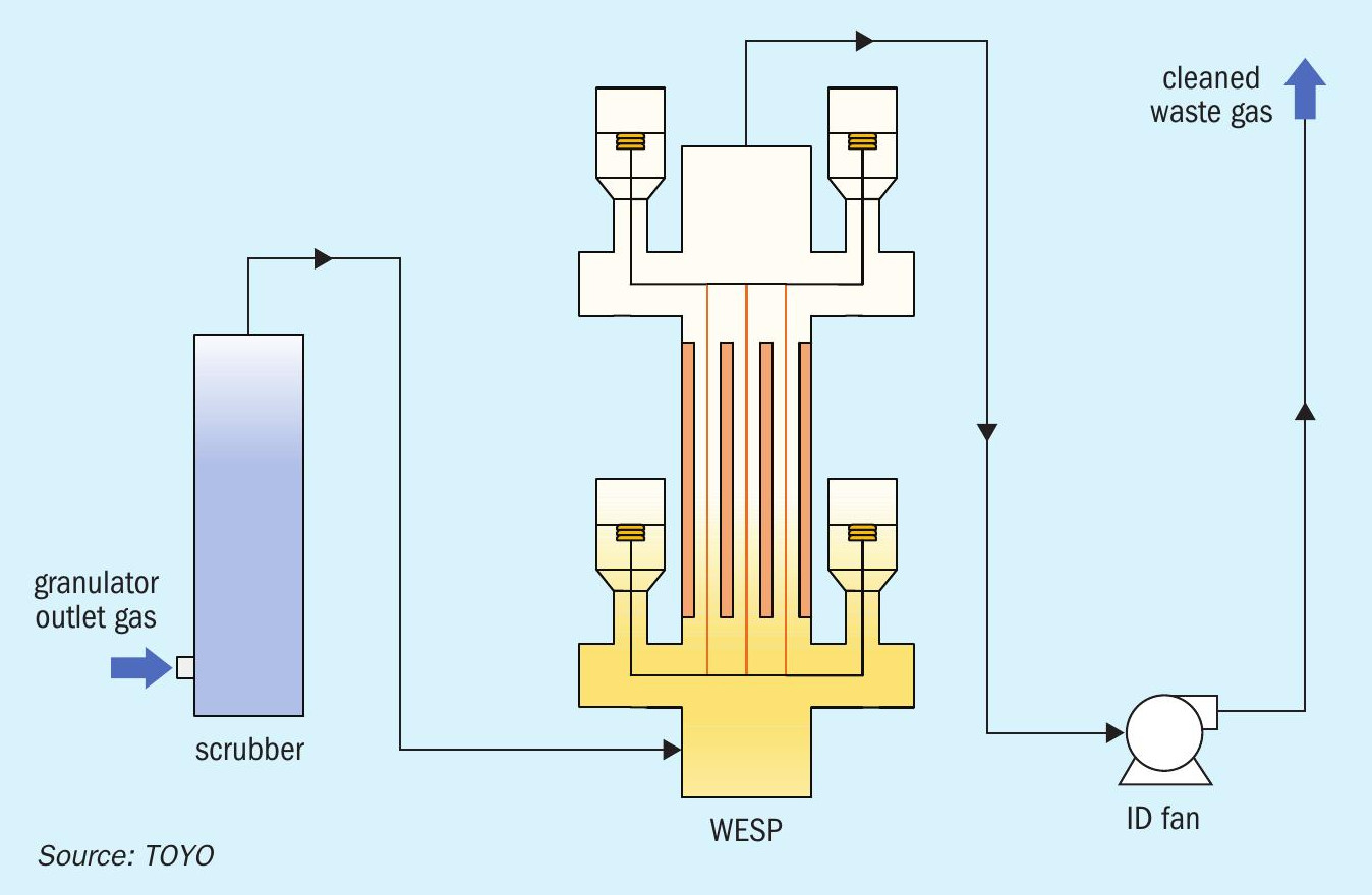
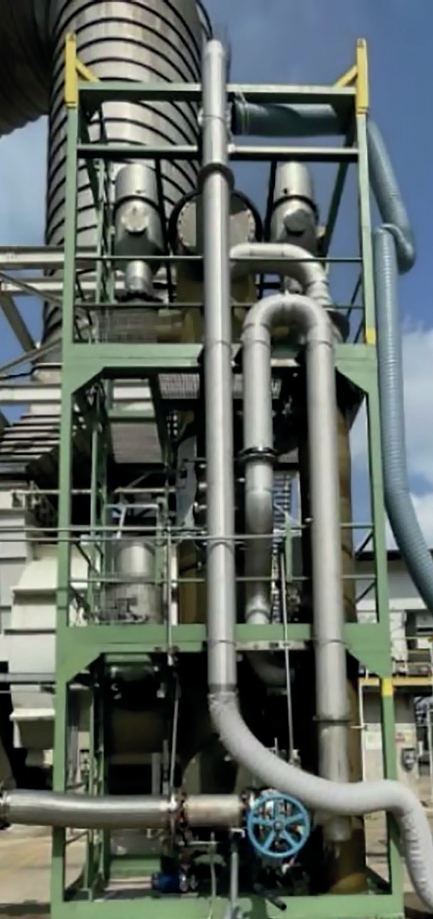
Figs. 2 and 3 show the schematic flow and the side view of the pilot plant, respectively. The pilot plant consists of a scrubber, an induced-draft fan (ID fan) and the AWS WESP unit. The gas containing urea dust from the granulator was first introduced to the scrubber section of the pilot plant, where the urea dust concentration was adjusted to desired levels before being introduced to the WESP, where the remaining fine urea dust and mist were removed. The cleaned waste gas from the WESP was drawn by the ID fan, and then discharged to the atmosphere via a stack.
Dust removal performance of the AWS WESP
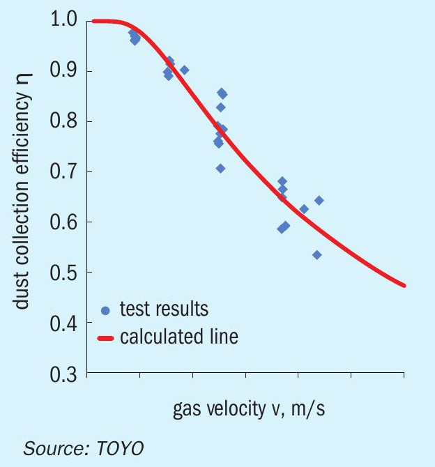
The pilot plant test confirmed that the WESP could effectively remove the urea dust from the exhaust gas from the granulator, achieving a urea dust concentration of below 5 mg/Nm3 . The graph in Fig. 4 shows dust collection efficiency η against gas velocity v in the collecting tubes.
In equation (1), dust collecting surface A and gas flow rate Q are represented as
A = 2πrLN and Q = πr2 vN
Where:
r = radius of the collecting tubes (m)
L = length of the collecting tubes (m)
N = number of collecting tubes
v = gas velocity (m/s)
Therefore, the dust collection efficiency can be expressed as a function of gas velocity by substituting dust collecting surface A and gas flow rate Q into equation (1).
In Fig. 4, the red solid line shows the dust collection efficiency calculated by equation (1) using the migration velocity obtained in the pilot plant tests. The blue dots show the actual data measured in the tests. The tests were carried out by varying the urea dust concentration at the WESP inlet and the gas velocity in the collecting tubes over a wide range.
As a standard practice, the WESP is designed to operate within a low-velocity range, in order to minimise risks of droplet entrainment at the outlet and to avoid interference with the corona discharge. The pilot plant tests showed that the WESP dust collection efficiency aligns well with the calculated values, even at higher gas velocities. Furthermore, the tests confirmed that the WESP can be designed for a broad range of velocities, maintaining efficiency without being affected by the urea dust concentration at the inlet. This indicates that integrating pre-treatment equipment with the WESP can lead to an optimised system design for consistent dust collection performance.
Migration velocity
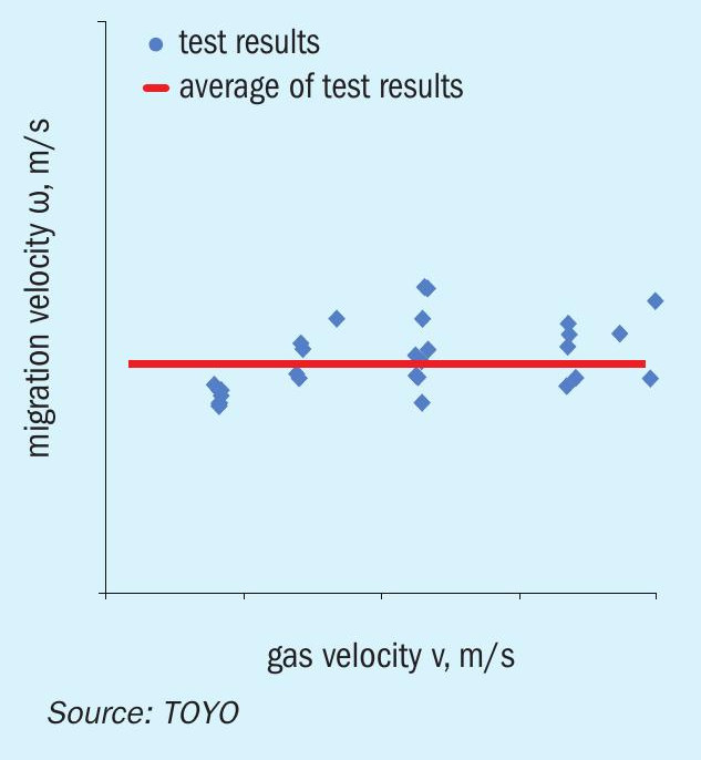
Fig. 5 shows observed migration velocity ω calculated by equation (1) against gas velocity v in the collecting tubes at a certain voltage (blue dots). The red line represents averaged migration velocity. As shown in Fig. 5, the migration velocity was almost constant regardless of the gas velocity in the collecting tubes, although it has been generally reported that increasing the gas velocity in the collecting tubes interferes with corona discharge and reduces migration velocity.
Operability and maintainability
The pilot plant was operated for a cumulative total of more than 300 hours, including a 108-hour trial operation without washing the collecting tubes and discharge electrodes. No deterioration in the WESP performance was observed in the period of the trial run, and no accumulation of urea dust was observed on the collecting tubes and discharge electrodes after the trial operation. The operation and inspection results indicate that long-term continuous operation of an industrial scale WESP without influencing the operation of commercial granulation units is possible with scheduled online washing.
Integration of WESP and TOYO’s dust scrubber
Based on the test results, TOYO is now ready to design a WESP scrubbing system by integrating AWS’s WESP and TOYO’s dust scrubber. Fig. 6 shows a typical arrangement of a WESP added to the scrubber. In case of direct installation on a dust scrubber, the WESP outer size could be the same as the dust scrubber, and a common support/structure can be utilised. Such an arrangement is advantageous in reducing plot area compared to installing a WESP separately from the dust scrubber. On the other hand, when installed downstream of an ID fan, the WESP can be installed at a lower position. Since the WESP is a heavy item of equipment, it is important to consider the foundation strength and the feasibility of adding additional steel structures to determine the location of the WESP especially when adding to an existing plant. The integration of the WESP and TOYO’s dust scrubber optimises the system to achieve urea dust emission of less than 5 mg/Nm3 with a total pressure loss of less than 100 mm H2O. This is a significant improvement compared to the 500 mm H2O pressure loss in other conventional WESP and dust scrubbing systems. 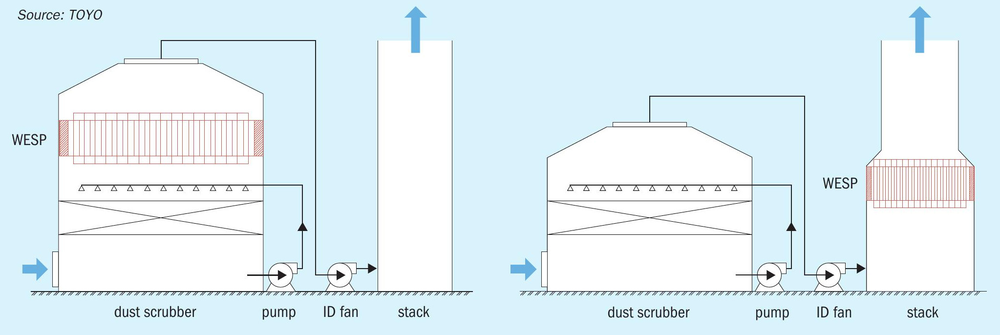
As the gas velocity increases, the number of collecting tubes decreases, leading to a certain reduction in capex, but some increase in opex due to the increased pressure loss in the WESP. AWS and TOYO can provide a WESP with an optimised gas velocity taking this into consideration.