Nitrogen+Syngas 392 Nov-Dec 2024

30 November 2024
How to solve stripper efficiency issues (part 3)
In Part 3 of this series on stripper efficiency issues, we continue the discussion on some some of the many causes of lower stripper efficiency. Here we discuss liquid divider fouling and bad installation of liquid dividers.
Liquid divider fouling
A perfect liquid divider system on the top tubesheet of the stripper is vital to achieve a higher stripper efficiency. Each liquid divider contains a number of liquid divider holes, which distribute the liquid from the reactor evenly over the complete surface at the top of the stripper tube. This assures that the solution flows as a falling film downwards inside the tube. Any tubes with clogged liquid divider holes will receive less liquid and will need to be compensated by the other tubes, which will receive more and potentially too much liquid. Furthermore, the tube(s) with less liquid load will have a lower flow resistance to the up-flowing gas than the tubes with more liquid load. This will result in maldistribution of the gas and the CO2 feed, a lower stripper efficiency and higher corrosion rates in certain tubes.
It is important that all the liquid from the reactor flows through the holes in the liquid dividers at the top of the stripper. In this way, the liquid dividers act like a filter in the high-pressure urea synthesis section. Fouling of the liquid distributor holes can be caused by several factors: oil, fibres, foreign materials, iron- and chromium-oxides or a combination of these.
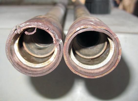
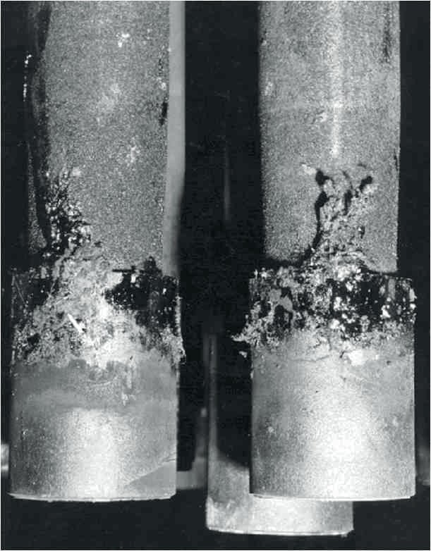
Photo 1 shows an example of oil fouling of the liquid dividers. This was a major issue in the early years after the invention of the CO2 stripper, when design plant capacities were relatively small and reciprocating CO2 compressors were applied. The oil from the CO2 compressors caused fouling in many urea plants resulting in a heavy tar type of fouling caused by the temperatures and the stripping effect of the gas. Major efforts were made to find solutions: Stamicarbon discovered that certain oils were more prone to cause fouling than others and specified which oils were preferred in these compressors. Another solution was the development of a dry seal system developed in China as there are still many small urea plants in operation in China with reciprocating CO2 compressors.
1.
Oil can also originate from the oil seals of reciprocating high-pressure ammonia pumps as well as from the ammonia feed from the ammonia plant. Jo Eijkenboom, at a time when working for Stamicarbon, developed the water seal system for reciprocating high-pressure ammonia pumps, which is now applied by all vendors. Note that the reciprocating high-pressure carbamate pump operates with a water flush system of its stuffing boxes.
Fibres can originate from the packing rings of the stuffing boxes in reciprocating compressors and pumps, especially at end of lifetime conditions.
Nowadays, with larger design plant capacities one typically sees integrally geared or centrifugal CO2 compressors and centrifugal high-pressure pumps.
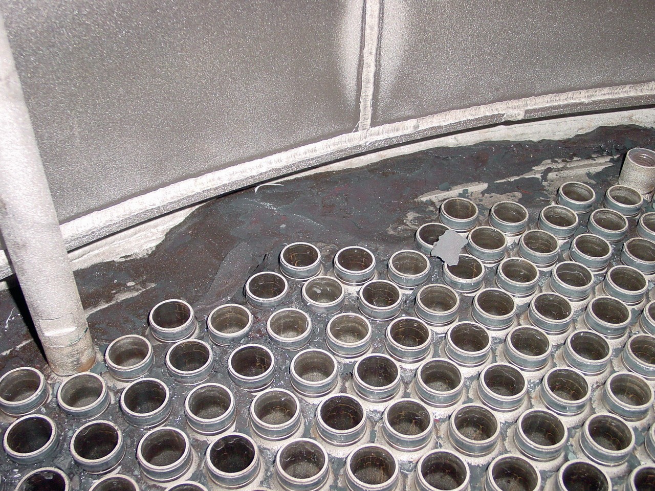
Fines and scaling can also cause clogging of the liquid distributor holes. These fines are typically iron- and chromium-oxides and are a result of the unavoidable passive corrosion rate of ammonium carbamate on the austenitic and super-duplex materials of construction applied. Active corrosion with its much higher corrosion rates can also cause these fines. In addition, fines resulting from grinding during a turnaround will oxidise and form these fines. Note that nickel forms a reaction with ammonia and remains dissolved in the solution. Photo 2 shows examples of the fouling at the top of the stripper caused by these fines. The fines can typically be removed relatively easily and it is advised to remove them when they complicate the proper installation of the liquid dividers on the stripper tubes.
2.
Bad installation of liquid dividers
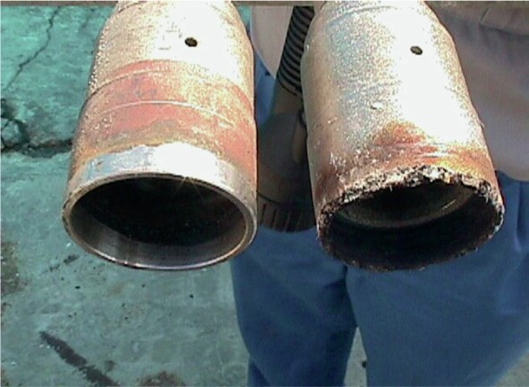
Another cause for low stripper efficiency is the bad installation or bad quality of the liquid dividers. Low stripper efficiency can also be caused by cross cut end attack corrosion at end of lifetime conditions, see photo 3, which shows a normal liquid distributor on the left and a liquid distributor at end of life on the right.
3.
Stamicarbon and Alleima have solved this issue with Safurex® Degree° liquid distributors. This material is fabricated via the Hot Isostatic Pressing (HIP) method, which results in an isotropic and fine-grained microstructure, improving corrosion resistance and also enhancing the material’s mechanical properties at low temperatures.
Bad installation procedures can damage the gasket and/or the bottom of the liquid distributor causing leakages between the liquid divider and the tube end resulting a lower stripper efficiencies as shown in photo 4.
4.