Nitrogen+Syngas 393 Jan-Feb 2025

31 January 2025
How to solve stripper efficiency issues (part 4)
In Part 4 of this series on stripper efficiency issues, we continue to look at the causes of lower stripper efficiency with a discussion on the high delta-P range of liquid dividers.
High delta-P range of liquid dividers
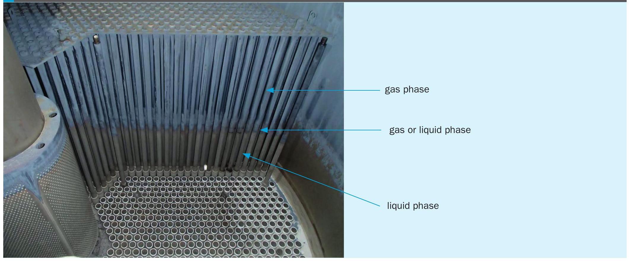
To achieve efficient and satisfactory operation of the stripper it is necessary for the liquid flow and the carbon dioxide (CO2) flow to be uniformly distributed over the tubes and for the liquid flowing through each tube to be uniformly distributed over the wall. To ensure this, each tube is equipped with a distributor containing flow restrictions in the form of holes for gas and liquid, which have been designed for capacities such that variations in gas density and differences in flow resistance between the gas and liquid in the tube cannot disturb the distribution.
Liquid flow restrictions
Let us first consider the liquid flow restrictions. While there is only one flow restriction for the gas in each tube, there are three liquid restrictions. With three circular holes arranged at equal intervals over the circumference of the tube, uniform distribution of liquid over the wall of the tube is obtained if the liquid flow is large enough.
The pressure drop (delta-P) across each liquid hole depends solely on the height of the liquid above the hole (if the gas flow is assumed to be unimpeded). In view of possible deviations from the average liquid load, the following two factors are of importance for any given single tube and for a set of tubes:
- deviations in the diameter of the liquid holes resulting from the tolerance applied in drilling and/or due to corrosion during its lifetime (as a result from cross cut end attack corrosion);
- non-uniformity of the liquid height in the head of the stripper due to a slant of the stripper and/or to the resistance to the liquid flow occurring between the distributors and the gas tubes in the stripper head.
In cases where these factors occur in combination, considerable deviations from the average liquid load may occur. When the diameter of the holes is small, and hence, the level of the liquid high, it is the deviation in diameter of the holes that has the stronger effect, whereas if the holes are large and the liquid level is low, the slant of the stripper and the concavity of the liquid surface are the predominant influences.
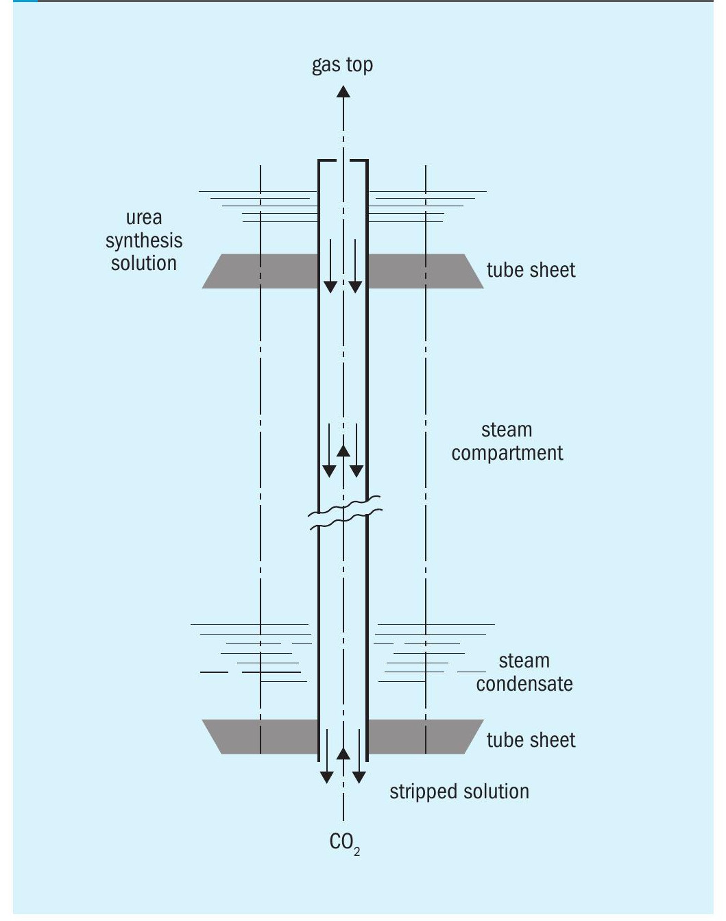
The driving force for the gas flow is the difference in pressure between the top and bottom parts of the stripper. As calculations have shown that the pressure drops caused by the friction between the gas flow and the liquid film and by the acceleration of the expelled gas from (downward) liquid velocity to (upward) gas velocity are negligible, the overall pressure difference between top and bottom can be calculated as the sum of the pressure drop over the gas hole and the static head of the gas column in the tube. This head can only be calculated by integration, since the gas density varies over the length of the tube. At every level in a tube the gas density depends on the temperature and the ammonia to carbon dioxide ratio and, consequently, on the mass flows of the liquid at the top and the CO2 gas at the bottom. The pressure difference between top and bottom is equal for all tubes in the stripper. Because of the influence of the amount of liquid on the gas density, not only the liquid flow but also the flow of CO2 may show a deviation in a limited number of tubes.
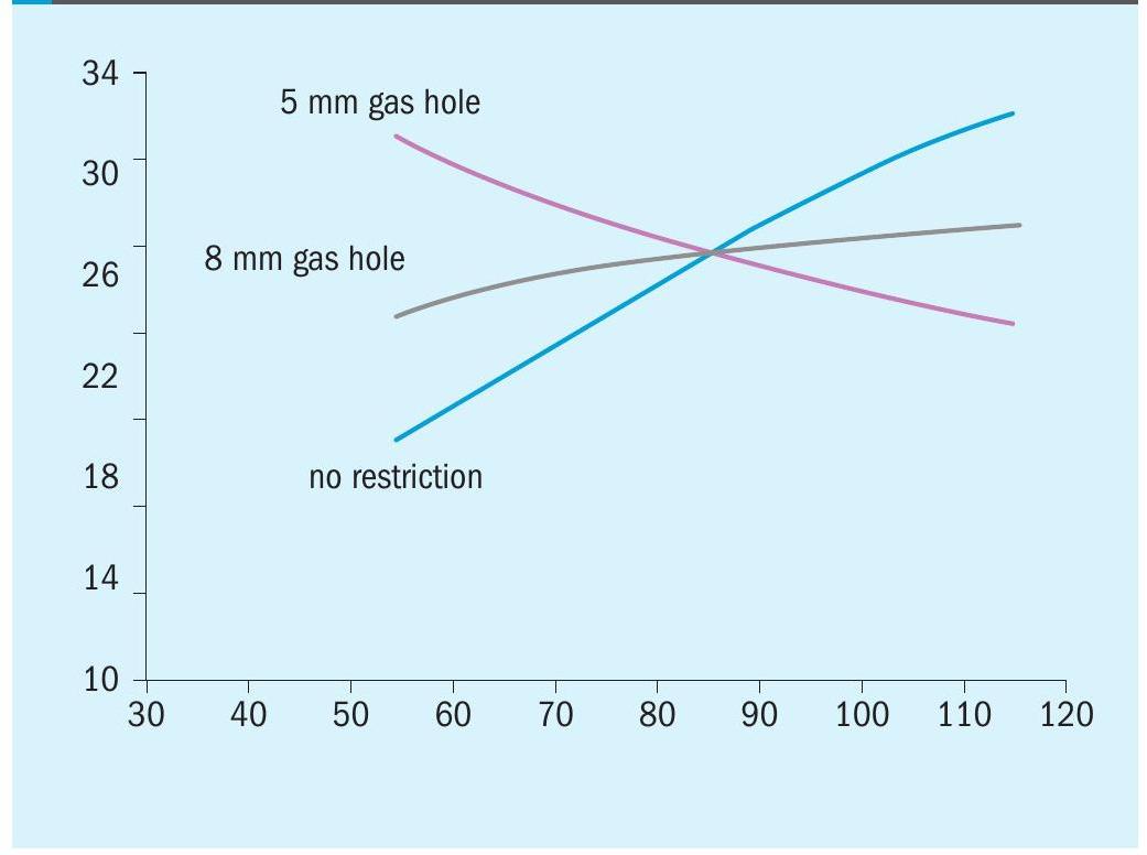
If the gas hole is small, say 5 mm, the pressure drop across the gas hole is notable. Enlargement of the flow of liquid to a single tube or to a set of tubes will tend to increase both the flow of gas leaving at the top and the pressure drop across the gas hole. This is counterbalanced by a decrease of the flow of fresh CO2 gas to the tube(s) under consideration. If there are large gas holes, or if the gas flow is completely unrestricted, the static head of the gas column in the tube will be the decisive factor. An increase of the flow of liquid to a single tube will result in an increased flow of CO2 so that the gas density in the tube is maintained at a constant value. The liquid/gas ratio remains more or less constant; the risk of flooding of the liquid in a tube due to the upward flow of gas becoming too large is clearly greater than if smaller gas holes are used.
Deviations from average liquid load
Possible deviations from the average liquid load can be caused, for example, by deviations in the diameter of the liquid holes and by non-uniformity of the liquid height in the head of the stripper.
Diameter of the liquid holes
Deviations in the diameter of the liquid holes can result from the tolerance applied in drilling and/or due to corrosion during its lifetime (as a result of cross cut end attack corrosion).
On top of the stripper tubes distributors are installed to provide proper distribution of the liquid as well as the gas. Typically these distributors are called liquid distributors. To avoid any misunderstanding, these will be referred to as ferrules in this article.
The diameter of the liquid holes increases in time due to cross cut end attack corrosion. The corrosion rates differ per direction as a result of the fabrication process of the ferrules. This means the original round liquid holes become oval over time. It is very important to assure that the delta P over the liquid holes of all installed ferrules fall within a certain range (delta P +/– x% as specified by the licensor) so that all tubes receive the same amount of liquid and can realise a high stripper efficiency. It is good practice to perform a delta-P measurement by means of a certain air flow to measure the delta P of each ferrule. Over time the average delta-P will decrease due to the larger liquid holes and the range of delta-P will become wider.
If a certain number of ferrules have a delta-P which falls outside the acceptable range (average delta P +/– x%), they will need to be replaced by ones with a delta-P that fall within the range. As all liquid holes increase in time it makes sense to rotate the spare ferrules into the set of installed ferrules. Safurex Star ferrules are made according to the Hot Isostatic Pressing (HIP) fabrication process reducing significantly the cross cut end attack issues and realising a longer lifetime of the ferrules.
Non-uniformity of the liquid height
Deviations from the average liquid load can also be caused by non-uniformity of the liquid height in the head of the stripper due to a slant of the stripper (i.e. not perfectly vertical) and to the resistance to the liquid flow occurring between the ferrules in the stripper head.
The Shangdong Hualu Hengsheng Group in China used a caliber to check the slant (verticality) of its CO2 stripper in their CO2 stripping urea plant. The urea plant started up in 2007 and operates currently at a capacity of 1,300 t/d. Before the alignment the stripper bottom liquid outlet temperature was some 173174°C and the stripper efficiency 79% at 100% plant load. After proper alignment the stripper bottom liquid outlet temperature reduced to some 170-171°C and the stripper efficiency increased to 81% at 110% plant load.
It is good practice to check the liquid level in the top of the stripper over the diameter in two directions (north-south and east-west).
In case the liquid level is not equal over the complete diameter, it means that some tubes receive more liquid than others, which leads to a lower stripper efficiency. It is advisable to contact the licensor in that case in order to optimise the design of the liquid distribution in the top of the stripper.