Sulphur 417 Mar-Apr 2025
18 March 2025
How to successfully run a four-year acid plant campaign
SULPHURIC ACID PLANT OPERATIONS
How to successfully run a four-year acid plant campaign
Apart from having a good plant design, good maintenance practices and good operational discipline are key to optimise the performance of an acid plant and to protect it from corrosion and achieve a long life. B. Mumba, T. Mwanza and P. Ng’ambi of Kansanshi Mining PLC explore the Kansanshi sulphuric acid plant operations and the key parameters monitored and practices adopted that have helped to extend the catalyst campaigns from two years to four years.
Kansanshi copper smelter was commissioned in March 2015. The off gas from the primary smelting furnace, Isasmelt™ furnace, and off gases from the Pierce Smith converters are treated in a single 4,500 t/d acid plant. The successful operation of the acid plant has been very important to the successful operation of the smelter and has allowed the smelter to treat concentrates at a rate of more than 110% of the design capacity. Details of the Kansanshi smelter operations and acid plant design and operations are described in other publications1,2 .
In the early years of the smelter operation, the acid plant ran for very short campaigns before stopping the plant to screen the catalyst, the shortest one was only 10 months. The decision to stop the plant was driven by high pressure drops across the catalyst beds, particularly Bed 1 and also the opportunity to screen during the smelter turnaround.
The original schedule for acid plant and smelter turnarounds were two years and four years respectively. The acid plant turnaround is centred around catalyst screening which takes between two weeks to one month to finish depending on the number of beds to be screened and the performance of the screening machines. The smelter shutdowns are usually scheduled for about 40 days which is enough time to screen all the beds. Therefore, any catalyst screening conducted outside of the scheduled times has a big impact on the smelter availability. It is therefore beneficial to reduce the frequency of catalyst screening by screening only during the smelter turnarounds.
This article explains some of the operations and maintenance strategies that have been adopted and adapted at Kansanshi smelter that have helped to increase the acid plant turnaround time from two years to four years while still maintaining low pressure drops on the SO2 converter beds and maintaining concentrate treatment above the rated plant capacity.
Brief process description
Fig. 1 below shows the general process flow of the Kansanshi Smelter. Copper concentrates are smelted in an Isasmelt furnace which produces a matte of between 58% and 60% Cu. The off gas from the furnace goes through a waste heat boiler and spray coolers where it is cooled to between 330°C and 350°C. The gas is passed through a dry electrostatic precipitator (ESP) where the majority of the dust carry over is captured and removed before it is taken into the gas cleaning plant.
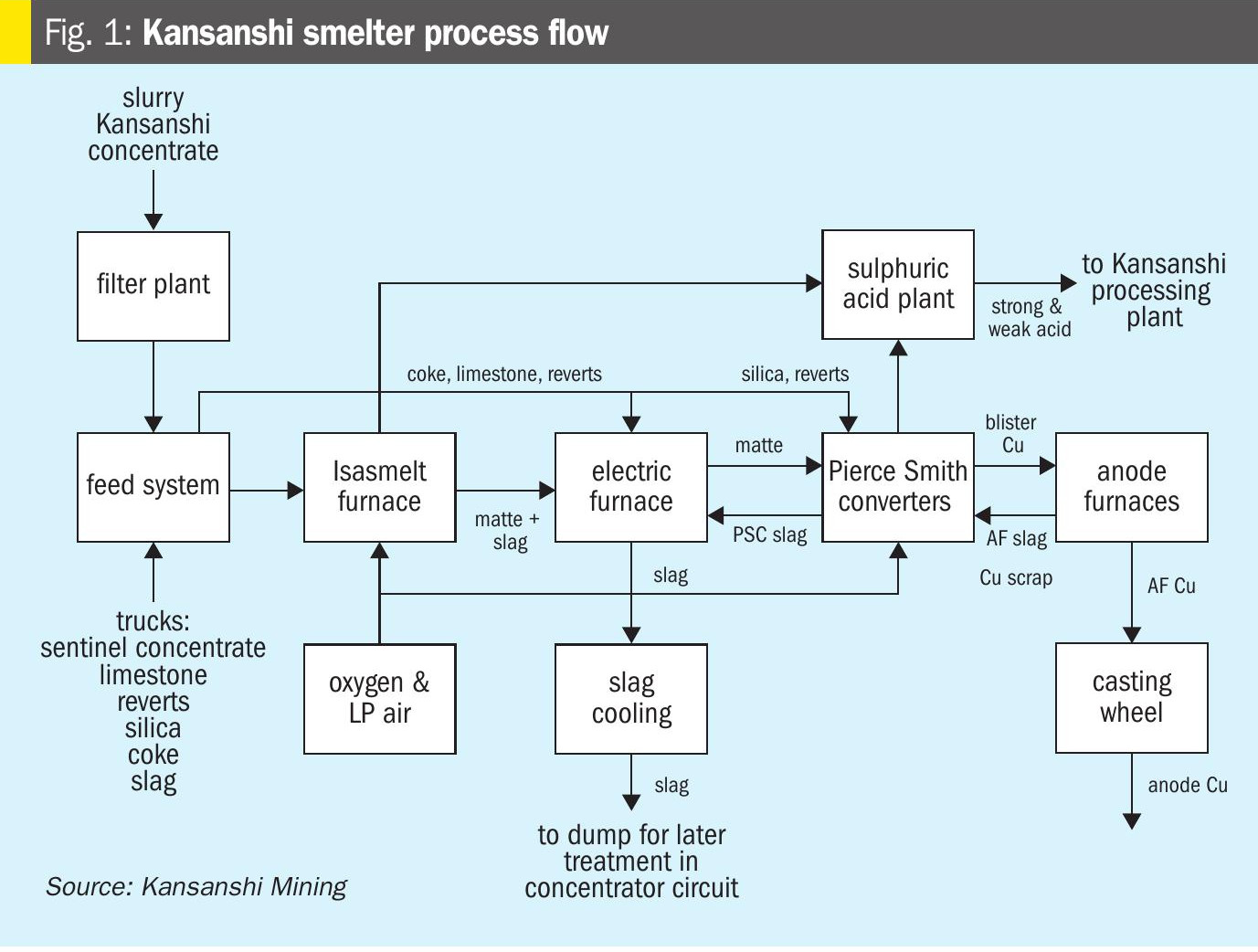
The matte from the Isasmelt is converted to blister copper in Pierce-Smith converters (PSCs). Each PSC is coupled with a standalone primary gas cooling and cleaning system which consist of an evaporative cooling chamber (ECC), a high efficiency scrubber, a droplet separator and an intermediate blower.
The gases from the Isasmelt route and the PSCs meet in a common duct before they go for final cooling in two parallel packed gas cooling towers (PGCTs) and final gas cleaning in four parallel wet electrostatic precipitator (WESPs) trains, each consist of one primary WESP and one secondary WESP.
The final gas is taken to the acid plant for conversion and absorption processes.
Smelter and acid plant performance
Plant availability
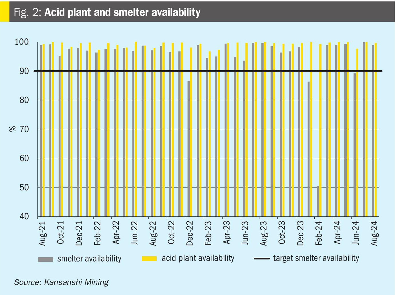
The acid plant operations are an integral part of the smelter operations hence the smelter availability is highly dependent on the acid plant availability. Fig. 2 shows the overall smelter availability and the acid plant availability on a monthly basis between August 2021 and August 2024. It can be seen from the graph that the acid plant availability was consistently above the plant design of 90%. During this period, there has been no requirement to screen the catalyst which has contributed to higher than design availability for acid plant. The overall smelter availability was also above 90% for most of the months during the period except for three months in which there were unplanned failures on the oxygen plant and Isasmelt.
Catalyst screening history
Table 1 shows the history of the catalyst screening. During nine years of operation of Kansanshi Smelter, the catalyst in Bed 1 has been screened a total of five times while the rest of the beds have been screened twice only. The catalyst has been screened both on scheduled shutdowns during smelter turnarounds and on emergency stoppages because of high pressure drop across the catalyst beds, especially Bed 1. The catalyst screening can only be done during the dry season because the converter is located outside of any enclosed building and all the manholes are exposed to the outside weather.
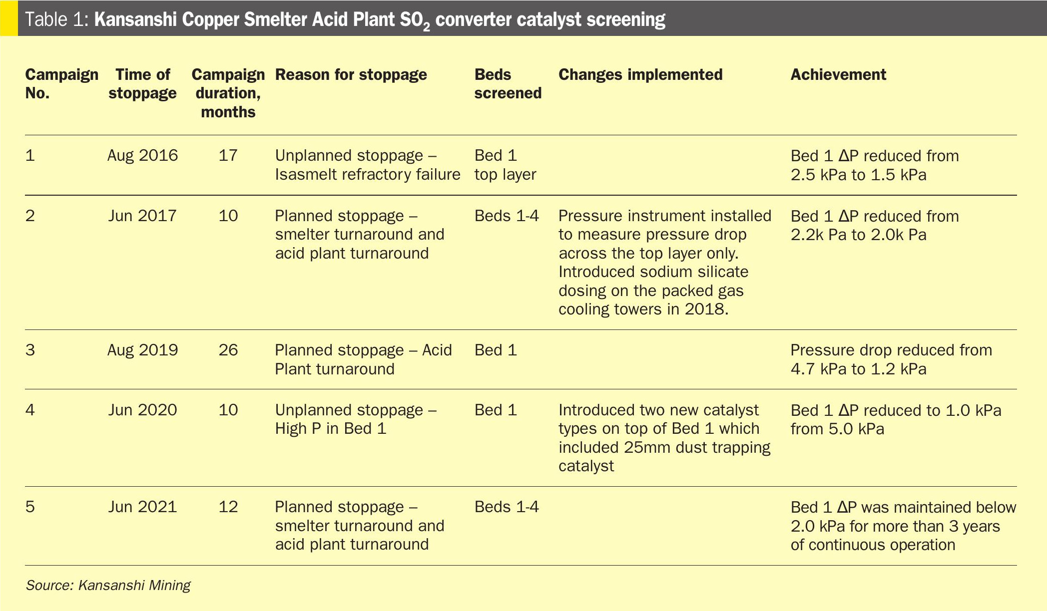
The first catalyst screening was carried out in 2016 during an unplanned stoppage of the smelter. Only the top half of Bed 1 was screened. At that time the pressure drop across the bed had already reached 2.5 kPa from 1.3 kPa after only one year of operation.
The following catalyst screening was during a planned smelter turnaround in 2017. All the four beds were screened; it was observed that in bed 1 the catalyst was deteriorating quickly. A Layer of catalyst dust was found in the middle of the top layer resulting in high pressure drop. Fig. 3 shows the Bed 1 pressure drop from 2015 to September 2024 together with catalyst screening shutdowns.
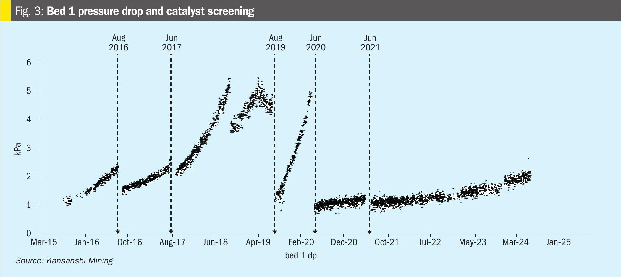
After 2017 smelter turnaround shutdown target for smelter campaigns was increased from two years to four years. However, with only one year of operations, Bed 1 pressure had increased rapidly, to more than 5 kPa hence a catalyst screening shutdown was required for Bed 1 only in 2019. The root cause of the more rapid catalyst deterioration in Bed 1 was unknown. An additional pressure transmitter was installed in the middle of the bed to assist with troubleshooting. It was found that pressure drop in the top of the catalyst bed was increasing more rapidly than the bottom half.
The suspected cause of the catalyst degradation was fluorine which at that time was not analysed in concentrates or in the acid. When the feed concentrates were analysed and it was found that the concentration of fluorine was much more than the concentrations used for the design of the plant. To address the problem, sodium silicate dosing was introduced in July 2018 on the packed gas cooling tower to scrub off the fluorine in the gas before it reached the catalyst. The smelter lab was equipped with a fluoride analyser to measure once per shift the fluorine levels in both the strong acid and weak acids as well as a daily assay of fluorine in the feed concentrates.
Even after the sodium silicate dosing was implemented, the problem of rapid increase in the pressure drop across Bed 1 did not go away, but rather worsened as the dust continued to form in the bed. After 2019 catalyst screening shutdown, another shutdown for screening Bed 1 catalyst was necessary in 2020 only 10 months after the previous screening. This was driven by rapid increase of pressure drop across Bed 1 together with significantly increased pressure drop across the hot heat exchanger.
In the 2020 shutdown, half of the top layer of bed 1 was changed to a new type of catalyst and the hot heat exchanger was cleaned. The scale sample taken from the hot heat exchanger indicated that it had been blocked by catalyst dust. The change of the catalyst type eventually stopped the rapid deterioration of catalyst and an improvement in the performance of the catalytic converter was observed. In 2021 all the converter beds were screened again during the scheduled smelter turnaround shutdown and the remaining portion of the Bed 1 top layer was changed to the new type of catalyst and a dust capturing layer was introduced on top of Bed 1.
The converter was entered in January 2024 during an unplanned smelter stoppage to check the condition of the catalyst after 2.5 years of continuous operation and the catalyst sampled in a few places and it was found to be in good condition without any pockets of dust.
Strategies for managing and improving acid plant campaign
Gas cleaning plant operations
The operations and efficiency of the gas cleaning plant (GCP) has a large bearing on both availability of the acid plant and the length of campaign the catalyst can achieve3. The GCP removes dangerous poisons such as dust, halides, mercury, excess moisture etc. that would affect both the acid absorption system and catalytic converter if not removed from the gas. Attention must be paid to all operations in the GCP to minimise plant downtime and enhance efficiency. Below are some of the strategies that have been adopted and adapted at Kansanshi in the gas cleaning section.
Maintaining high pressure drop on the high efficiency scrubber’s dampers
The high efficiency scrubbers (HES) require a high pressure drop across the damper on the scrubber throat for the dust in the gas stream to be caught by the water droplets in the circulating slurry. Each of the HES units is equipped with a movable damper. To maintain a high differential pressure, the damper position is continuously adjusted by a differential pressure controller; the damper is partially closed when the gas flow is low and opened more when the gas flow is high. There are two sets of transmitters to measure the pressure drop on each unit, this is for redundancy in case of bad readings from one instrument the control room operator switches over to the second one. On the PSCs gas route, the HES have several sets of setpoints for the different operating modes of the converters i.e. one set of parameters for slag blow mode and another for copper blow mode.
Maintaining high liquid to gas ratio in scrubbers and PGCTs
The scrubbers and the packed gas cooling towers are supplied with excess liquid. Each of the units has two independent circulation circuits to supply the quenching and the cooling liquids respectively. Each circuit supplies enough liquid to sufficiently cool the incoming off gas for a limited period, about 30 minutes. The oversupply of liquid ensures that no hot gas goes past the HES and protects the FRP ducting downstream.
Maintain high weak acid bleed-off
High volumes of make-up water added to GCP so that the bleed-off of solids from the system is very high. This intervention has not solved the problems of solids accumulating in the circulation pipes but has reduced it to a small extent. The high make-up water dilutes the acid concentration in the system from maximum of 10% to 11% to only about 1% H2SO4. This reduces the corrosiveness of the acid to the equipment and bolts4.
Data recording and trending
The analysis of trends plays an important role in the operations of the smelter. The data collected from the DCS and manual log sheets are recorded in a process historian (PI system). Trends are monitored both by the control room and any plant personnel with access to a computer. Some trends have been developed specifically to assist the control room operator to more quickly check different sections of the plant. Daily monitoring of the trends has helped to ensure that all the units are running efficiently and deviations in the process can be worked on in a timely manner. Planned maintenance is also scheduled based on equipment performance assessed from the data from trends.
Manual cleaning of WESP tubes
The dust particles that are captured in the WESPs are collected on the inside of the tube walls. The solids are washed from the tubes using a low pressure flushing system that uses weak acid. However, on the primary WESPs, the solids form very hard buildups that are very sticky to the tube walls cannot be washed out during the normal flushing. When the build-ups grow, they interfere with the operation of the units by high frequency of flashovers. The affected WESPs transformer PLC then automatically reduces the power supply to the unit to maintain the flashovers within safe limits, this reduces the dust and mist capturing efficiency. The change is observed through the trends when the power input is reduced.
The WESP train has to be stopped and the build-ups are cleaned out manually. The cleaning is laborious but eventually after cleaning the WESPs performance improves and cleaning efficiency is maintained.
Cleaning quench tower ring pipes and nozzles during shutdown
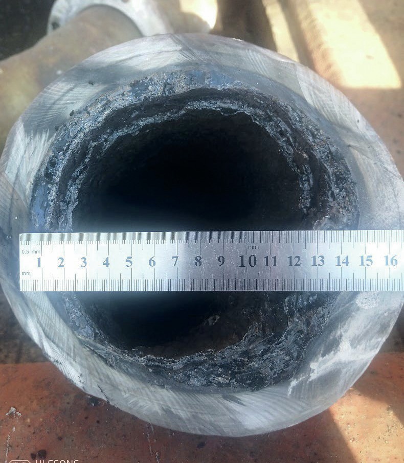
The Isasmelt quench weak acid circulation system also requires periodical manual cleaning. The solids circulating in the quench with weak acid slurry gradually build-up on the inside of the pipe walls then cause blockages (Fig. 4). The worst affected are the horizontal rings above the quench which distribute liquor to the nozzles. The cleaning can only be done when the Isasmelt off gas system is offline. Hence to manage this situation, the lines are opened up and cleaned in advance before the blockages become severe. This activity is always included in the scheduled shutdowns and also on all the opportunity shutdowns on the Isasmelt.
Sodium silicate dosing based on plant assays
Sodium silicate is dosed at the PGCTs to remove fluorine from the off gas before the catalytic converter. The amount of fluorine in the off gas is variable based on the mineralogy of the concentrates smelted in the Isasmelt. During the times when the concentrations of fluorine are very high the dosage of sodium silicate is increased while monitoring the residue fluorine in the strong acid which should be maintained below 1.0 ppm. When the concentration of fluorine is low, the dosage is gradually reduced and sometimes turned off as long as the fluorine concentration in the strong acid remains below 1.0 ppm. Excessive sodium silicate in the weak acid system can cause operational problems because it tends to precipitate and then blocks the plate heat exchangers that are used to cool the weak acid. Currently there is no online system to monitor the fluorine in the system, the assays are obtained from manual samples which are collected every shift.
Field operator’s routine checks
There are some routine activities that have been designed for the field operators to keep them engaged with the process. The operators collect readings from the instruments that do not show on the DCS such as HES pumps suction and discharge pressures, plate heat exchangers water side inlet and outlet pressures and WESP band heaters temperatures. The data are recorded at regular intervals in a manual log sheet by the control room operator and then recorded in the process historian at the end of the day. The data is then available for trends and other analysis. The routines are also helpful in capturing information that cannot be measured by the instruments such as acid leaks from flanges, blocked nozzles etc.
Gas cleaning plant maintenance
Apart from good operation practices, the maintenance strategies on the gas cleaning plant have to be good to achieve high plant availability. Some of the important maintenance strategies that have been implemented at Kansanshi are highlighted below.
Standby units on the HES and PGCTs
All the HES and the PGCTs have two independent circuits for the circulating weak acid. Each circuit supplies sufficient liquor to quench the incoming gas and keep the outlet gas temperature below the high limit. In normal operation, both circuits are always online and the gas source will be tripped out if one of the circuits is offline for more than 30 minutes. There is also a third pump on each unit that can be connected to either circuits as standby pump, therefore any of the circulation pumps can be taken out for maintenance while the plant is running. In the same way, the PGCTs have standby heat exchangers that allow for maintenance while the plant is online.
Change to more suitable materials of construction
Some areas of the gas cleaning have been changed to different materials of construction because of high rates of corrosion. For example, intermediate blower on the Isasmelt off gas route had a shaft and a casing that were originally made of rubber-lined mild steel while the impeller was made of a duplex stainless steel. Because of weak acid attack on both the rubber and the steels due to presence of high concentrations of HCl and HF, all the parts of the blower were changed to super duplex steel and the rubber linings were removed. Similar problems were experienced on the Isasmelt quench tower where weak acid was percolating through bricks and mortar to the mild steel shell and corroding it, the steel on the tower shell was changed to stainless steel. The Isasmelt scrubber cone was also made of rubber-lined mild steel originally but was changed to stainless steel after high rate of corrosion. The introduction of corrosion resistant steels eliminated the need for frequent maintenance on the equipment.
HES maintenance during PSC turnaround
When a PSC is taken offline for turnaround maintenance, the associated HES and intermediate blowers are also taken for extensive maintenance. The turnaround period is about three weeks which gives enough time for thorough checks on the HES which include refractory inspections and repairs, instrumentation calibrations, mechanical repair of all the pumps and the hydraulic system for the throat damper. The intermediate blower casings are opened up and impeller washed with pressure washer. All major overhaul maintenance is carried out during this period therefore during normal acid plant shutdowns there are no jobs to do on the converter off gas routes which free-up a lot of the resources to other areas.
Acid plant operations
The operations in the acid plant are also critical to ensure high plant availability and to extend the catalyst life. Some of the acid plant operating strategies are presented below.
Strict control of the acid concentration
The acid concentrations of the drying tower and absorber towers systems are maintained strictly at the setpoints of 96% and 98.5% respectively. On each system there are two online analysers for comparison during continuous operation. Each of the two online transmitters can be selected for control thus there is no lost time if one of them becomes faulty. In addition to the two online measurements, the operators collect two-hourly samples from both systems which are analysed in the field lab using an ultrasonic analyser, the results are recorded in the process historian for trends. At the end of every shift a sample of the acid from each circuit is taken to the smelter laboratory for check using a titration method. All these methods of counterchecking are done to make sure that the instruments are always reading correctly and any weak acid formed in the system is detected quickly.
Highly automated pressure control system
A feed forward control system was implemented to protect the SO2 converter from surges in pressure arising from situations such as the rolling-in and rolling-out of the PSCs. The pressure protection overrides the temperature control logic by opening the dampers in the area to ensure that the gas paths are open to allow the pressure surge to pass. The details of the pressure logic are described by Ng’ambi5 .
Highly automated temperature control
The SO2 converter temperature control is highly automated. It is always necessary for the temperature control dampers (TCVs) to be adjusting their positions in reaction to changes in gas flow rates and changing SO2 concentrations. The TCV positions are adjusted automatically by temperature control logic to maintain the setpoints. Operator interference is minimised and the plant recovers more quickly after flow disturbances when PSCs roll in or out. The TCVs also play an important role in holding heat inside the converter during prolonged shutdowns, the converter can hold the heat for up to three days without requiring the preheater for start-up.
High detail temperature monitoring
Each converter bed has more than one thermocouple installed on the inlets and outlets. Bed 2 and Bed 3 each have a total of four thermocouples, two for the inlet and two for the outlet, while Bed 4 has a total of six thermocouples with two extra thermocouples installed in the middle of the bed. The thermocouples are installed 180˚ apart. On Bed 1 there are a total of 18 thermocouples, six at each level, inlet middle and outlet.
Highly automated SO2 concentration control system
The feed gas SO2 concentration and volume are controlled by a feed forward system. The total SO2 flow in from the Isasmelt furnace is calculated from the concentrate feed rate and the concentrates blend SO2 factor. The SO2 gas from PSCs is calculated from the blowing rate of the particular converter and empirical SO2 factors for copper blow mode and for slag blow mode. The total gas flow from each SO2 source is calculated from the motor current not speed and pressure drop of the intermediate blower in that route.
The dilution air required is calculated from the calculated SO2 in feed gas as described above and the target setpoint selected by the control room operator.
There is a venturi-type flowmeter to measure the flow of the feed gas and compare to the feed forward calculations. The SO2 concentration is also measured by an online analyser to check the predicted concentration from the calculations. Oxygen concentration in feed gas is also measured online to check that it is sufficient for the conversion reactions.
The control room operator is able to manipulate the system using an adjustment calculation if they observe that there is deviation of the predicted SO2 concentration calculation against the analyser readings. The plant safety limits are configured in the DCS to prevent operator actions that would be dangerous for example the maximum gas flow to the plant is limited to 330,000 Nm3/h and the DCS prevents actions that would cause the flow to exceed this number.
Operator routine checks
Within the oxidation area and strong acid area, monitoring acid condensation in equipment and ducting on regular intervals is important. This assists in identifying the cold areas in the plant and works as one of the tools to monitor the efficiency of the filters at absorption and drying tower gas outlets.
The field operators check drain points at different points in the ducting, the gas-gas heat exchangers, SO2 blower suction and stack for condensate formation at least once per shift. The areas where acid condensate have been found more often are checked on more frequent intervals. Any condensate formed is drained into stainless steel buckets and discarded into the strong acid area sump. The volume of condensate collected from each drain point is recorded in the shift log.
The cold re-heat exchanger drain points have a high rate of condensate formation; hence the condensate is drained more frequently than from other collection points. In order to reduce manual handling of acidic condensate, the drained acid is transported in a pipe by using compressed air to a tank located within strong acid area. The level of the tank is monitored in the DCS and the level change per shift is recorded.
Maintaining a robust water treatment programme
Water treatment is very important in maintaining high quality water to cool the strong acid during acid absorption and also to cool the weak acid circulating at the PGCTs. Acid plant cooling water is cooled in an open cooling tower and raw water from rivers is used as make-up. The cooling water system is chemically treated using biocides, antiscalants and corrosion inhibitors to prevent corrosion of pipes and scaling of calcium. Part of the product sulphuric acid is dosed to the cooling tower to maintain the pH of the water within the targeted range.
Previously the water quality was poor which caused calcium scales to form in the acid coolers. The acid coolers started to have leaks on the same tubes that had scales. The plant was stopped frequently for long hours to plug the leaking tubes. One of the acid coolers was significantly damaged and had to be replaced.
The water treatment was contracted to a specialist with a more robust treatment programme and enhanced monitoring of the water quality. After the change, the scaling in the coolers was eliminated and there has not been reoccurrences of acid leaks on the coolers for more than five years of operation.
Strict control of acid temperatures and anodic protection on all acid coolers
All the acid coolers are made of stainless steel and have anodic protection systems. However, the acid temperature to the cooler must be below the maximum temperature limit to avoid corrosion. The most common scenario that leads to high acid temperatures is when there is a very high concentration of SO2 in the feed gas leading to a surge of SO3 coming to the absorption towers also causing a surge in the heat generated in absorption and dilution. Acid temperature warnings and trips have been set much lower temperatures than the safe limits. Therefore, the control room operator has enough time to check and make adjustments to the process before the temperatures reach unsafe regions.
Acid plant maintenance
Below are some of the maintenance strategies for maintaining high availability in the SO2 converter and strong acid sections.
Condition monitoring
All the major equipment in the acid plant have online instruments installed to monitor vibrations, pressures, temperatures etc. The data is recorded in the process historian for trending and analysis. In addition, a reliability engineer performs scheduled checks on the equipment in more detail with more sophisticated tools and keeps the data in separate database for analysis. Condition monitoring reports are sent out every two weeks to both operations and maintenance teams so that maintenance planning is always in line with operations planning.
Standby acid pumps
All the strong acid circulation and the product pumps have standby units installed, pump swap can be done online without shutting down the acid circulation system. In addition to that, there are fully assembled spare acid pumps kept in acid plant for quick pump change when there is an opportunity. The same type and size of acid circulation pumps are used for the drying tower and the absorption towers hence only one spare pump of this type is kept while a different spare pump is required for the product acid pump which is smaller.
Carefully planned shutdowns
The smelter has a scheduled shutdown every three months for all major maintenance works. Planning is critical to ensure that the shutdowns do not overun. All the disciplines and all the sections of the smelter are involved in the planning of the shutdowns and several meetings are held to discuss all the shutdown jobs to align and highlight all the resource requirements. A dedicated shutdown planner makes the final schedule which is followed during the shutdown.
Turnaround shutdowns are planned in a similar way with all disciplines involved and resources pooled together. More time is required to plan, all the major works have to be submitted at least one year before. The shutdown budget is also approved one year in advance which gives enough time for procuring the long lead items. Pre-shutdown activities planning and tracking is also part of the shutdown planning, the last months before shutdown are dedicated to pre-shutdown activities so that only activities that require the plant to be offline will be focussed on during the shutdown.
Strategic stock on site for all major plant equipment
The smelter keeps a strategic stock of the majority of the major equipment on site. Some of the equipment are long lead items and take several months to reach site when ordered while others are fast consumed components. A strategic stock ensures that there are no major shutdowns when an equipment fails.
Challenges
Hard scale forming in the Isasmelt quench weak acid pipes
The solids build-ups in the FRP pipes at the quench tower form a hard scale that is difficult to remove. To clean out the scale, the pipes have to be opened up on flanges and sometimes the FRP has to be to be cut to expose all the bends and corners. Sharp tools like steel bars are used to break the scale, since using a high pressure water gun does not break the scale. Apart from blocking the lines, the scales also block the strainers on the suction side of the acid circulation pumps leading to low currents and low flows and line blockage. Frequent cleaning of the pipes and the strainers is required sometimes causing downtime on the smelter.
An antiscalant chemical is dosed in the weak acid to make the scale softer when cleaning but it still doesn’t prevent the high number of stoppages to clean the build-ups.
WESP tubes cleaning
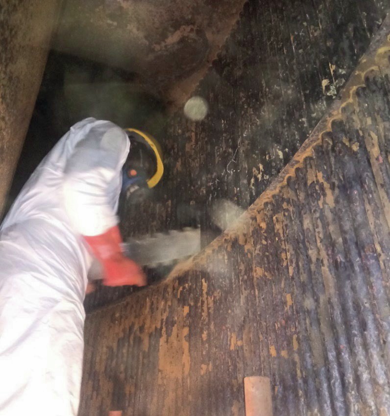
The cleaning of solids in the WESP tubes is also very challenging similar to what is experienced with the quench tower solids. The solids form hard scales that cannot be removed during flushing of the WESPs. The scales are found mostly on the top half of the primary WESPs. This is where most of the dust is trapped during operations. Hydroblasting is also not very efficient in removing the scales. Cleaning the tubes with hand tools is difficult because there is limited head room to manoeuvre around. The tubes are narrow and long hence long tools are needed and the electrodes in the centre of the tubes obstruct the movement of any tools. Sharp tools cannot be used for cleaning because there are some electrical connections that are imbedded in the FRP tubes that could be damaged while cleaning. Similarly, hydro-blasting machines have to be used carefully because the high pressure can break the tubes and electrical connections.
The hot heat exchanger frequently gets high pressure drop on the shell side (Fig. 5). This is caused by metal flakes that peel off from the pipes surfaces also by catalyst dust that builds up on surfaces and forms flakes. The high pressure drop causes feed restrictions.
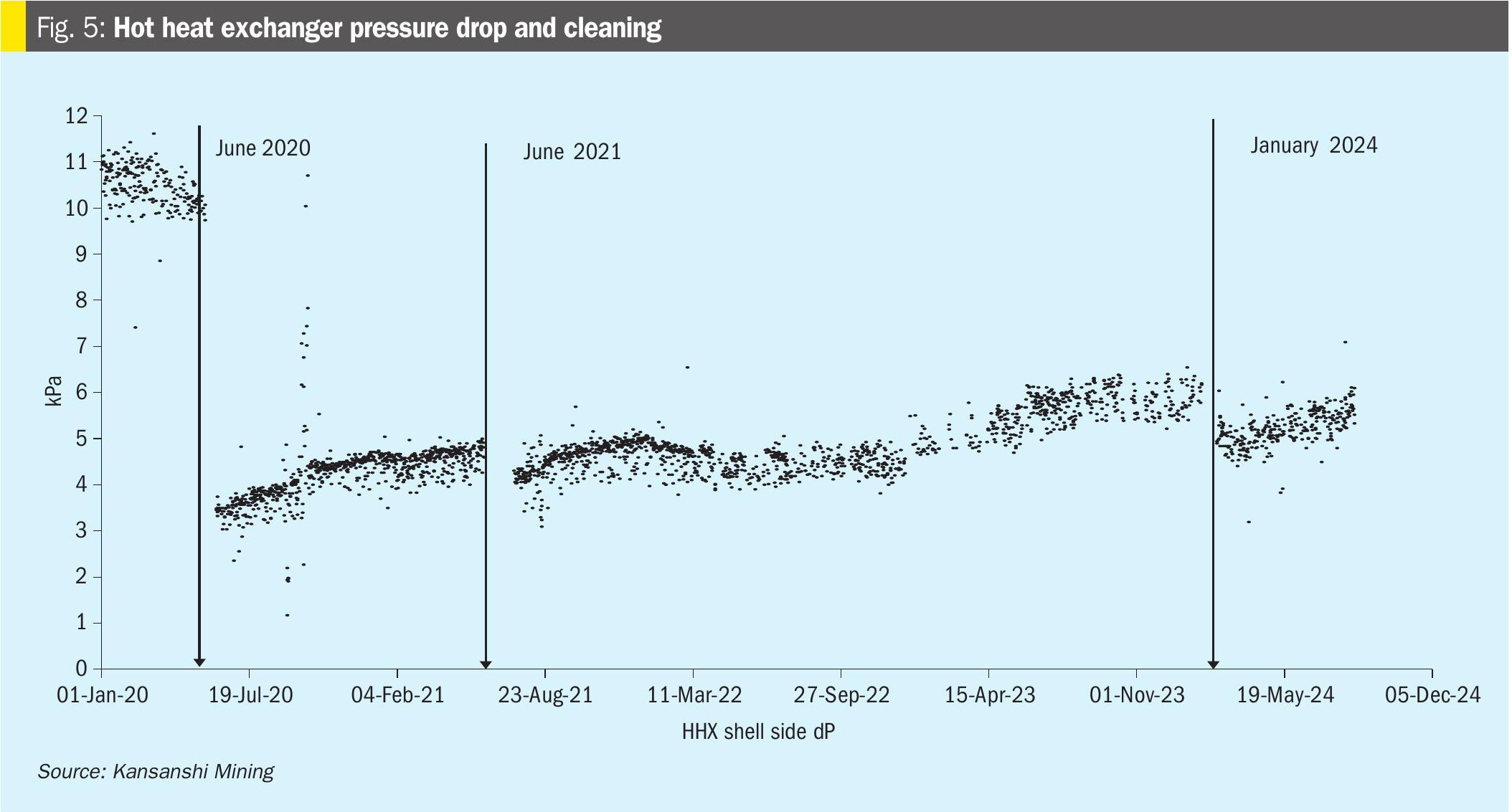
Cleaning of the tubes is difficult because of the restricted space between the tubes. Special knife plates were made to be used for cleaning however the reduction in the pressure drop after cleaning has not been very consistent (Fig. 6).
Power failures
The smelter experiences power failures and power disturbances several times every month. Power disturbances occur when there is high fluctuation in the supply voltage which trips out several equipment. Supply failure occurs when the power supply is completely cut off because of a fault at the utility company. The high frequency of these power disturbances and failures has a negative impact on the smelter availability.
Conclusions
The improvements in the acid plant campaign from two years to four years has been due to continuous improvements in many areas. The high availability of the plant is also due to strong commitment to good operations and maintenance practices. ■
References