Fertilizer International 525 Mar-Apr 2025
18 March 2025
Why the right cooling option matters
FOCUS ON COOLING EQUIPMENT
Why the right cooling option matters
For fertilizer producers, there is no one-size-fits-all solution when it comes to selecting the best cooling technology to handle their process needs. Each technology offers distinct advantages, whether it is minimising emissions, ensuring product quality, or helping to meet decarbonisation goals. Selecting the right technology is therefore crucial for today’s fertilizer operators. Igor Makarenko of Solex Thermal Science reviews the main cooling equipment options and their relative merits.
Introduction
This article examines three commonly used fertilizer cooling technologies – rotary drums, fluid beds and moving bed heat exchangers. The heat transfer, energy consumption and maintenance demands of each type are assessed. Their ability to support sustainability and decarbonisation efforts is also examined.
It is important to note that there is no one-size-fits-all solution for fertilizer cooling. Instead, each method offers distinct advantages and challenges. During equipment selection, it is therefore essential for operators to understand how the relative merits of different types of cooling equipment – each of which have contrasting strength and weaknesses – match up against their specific cooling requirements.

Rotary drum technology
Rotary drums are a popular and flexible method for drying and cooling fertilizers, given their large-scale and proven ability to process different product grades and cope with variable feed conditions. In a typical indirect rotary cooler, material introduced at one end is repeatedly raised and dropped using lifters as the material moves through the drum.
Process considerations with a rotary drum include:
• Minimising fine particle losses: Fine particles can be carried away with the warm exhaust air leading to product losses. Adjusting air velocity and using cyclones, bag filters and scrubbers does, however, help minimise potential environmental emissions.
• Coping with sticky materials: Some fertilizers are more hygroscopic than others. These may become sticky during the cooling process, causing agglomeration and affecting flowability. Regular cleaning of equipment internals is usually necessary to avoid buildup, as this adds extra weight to the drum and places unnecessary stress on components.
• Avoiding non-uniform cooling: Inconsistent air flow or temperature distribution can result in uneven cooling. This can affect product quality – for example, by transferring hot material to storage. Regular maintenance of the air distribution system and careful monitoring of operational parameters, such as the correct bed depth, are therefore essential prevent this.
• Energy consumption: Keeping a large size drum continually in motion requires a significant amount of energy. A typical rotary drum can consume more than 600kW of energy to achieve a 25°C temperature change at 100 t/h throughout.
Fluid bed technology
Fluidised beds, including vibrating types, are also commonly used to dry and cool fertilizers. Large volumes of ambient air are used to directly fluidise materials, so they flow from one end of the bed to the other, with drying and then cooling occurring as this happens. Fluidised beds can also be used for standalone cooling.
“The use of plate-based moving bed heat exchangers (MBHEs) at the cooling stage offers operators the opportunity to improve the energy efficiency of their process.”
Air has two functions in fluid bed technology. First, it creates the fluidised state enabling the product to flow. Second, it either heats or dries the material through direct contact. Fertilizer producers commonly use a combined fluid bed system, with the first unit operating as a dryer and the second unit as a cooler.
Alternatively, producers can combine a rotary drum dryer with a fluid bed cooler. In this arrangement, exhaust air from the fluid bed cooler can be used in the rotary drum dryer. This reduces the volume of ambient air required and, being pre-heated, also delivers an energy saving.
Process considerations with a fluid bed include:
• Maintaining fluidisation: Materials may not fluidise properly due to factors such as non-uniform particle size (including dust) and moisture content, leading to clumping or channeling across the moving bed. This issue can be avoided by ensuring uniform material characteristics, proper design of the distributor plate, and careful operating practices to ensure the correct bed depth is maintained
• Energy consumption: A fluid bed requires either a dedicated air treatment system, or access to a common treatment system, to comply with emission regulations. This requires a substantial energy input.
• Minimising fine particle losses: Fine particles can be carried away with the warm exhaust air leading to product losses. Similar to rotary coolers, adjusting air velocity and using cyclones, bag filters and scrubbers helps minimise potential environmental emissions.
• Coping with sticky materials: Some fertilizers are more hygroscopic than others. As with rotary coolers, materials can become sticky during the cooling process, causing agglomeration and affecting flowability. Regular cleaning/maintenance of the fluid bed’s perforated plate is therefore necessary to ensure consistent operation.
• Ensuring uniform cooling: Fluid beds should offer even cooling as long as they provide a consistent airflow and temperature distribution. Regular maintenance of the air distribution system and careful monitoring of operational parameters – such as correct bed depth – are essential, however.
Moving bed heat exchangers
The use of plate-based moving bed heat exchangers (MBHEs) at the cooling stage offers operators the opportunity to improve the energy efficiency of their process. They also offer the added benefits of less air consumption and fewer opex penalties.
First, a bucket elevator brings the fertilizer from the dryer, granulator or prilling tower into the heat exchanger’s inlet hopper – typically constructed with stainless steel 304L, 316L or 254 SMO. The product then flows at between 1-200 t/h at a controlled speed – usually 0.3 metres per minute – through the MBHE while cooling water flows counter-currently through internal channels within the plates (Figure 1).
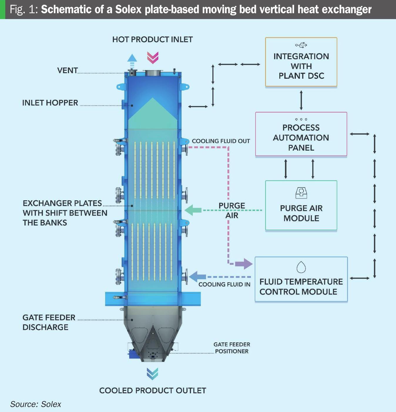
The product’s low downward velocity between the plates of the MBHE helps prevent the creation of fines/dust. Even in a worst-case scenario, producers can expect the amount of dust generated to be equal to that created at the feed point. Also, product contamination and degradation are largely avoided because of the slow and controlled movement of granules/prills and the lack of contact with air or water.
Chilled water for MBHEs is usually supplied by an existing chilled water circuit, plant cooling tower water or chilled ammonia. In some cases, natural water sources can be used by incorporating a closed-loop fluid temperature control circuit.
A complete standalone chilled water system can also be installed. By using a dedicated closed-loop circuit with a dedicated electric chiller and free-cooling non-evaporative towers, this ensures that no water intake from the operator is required.
If the MBHE is installed in a hot, humid location, a small amount of dehumidified purge air (1,000-2,500 Nm³/h) may need to be injected between the heat exchanger banks to prevent condensation and caking from occurring.
Process considerations with a plate-based heat exchanger include:
• Need to avoid caking: Caking can occur during the cooling process when the critical relative humidity temperature and dewpoint temperature of the air in the void space between the product particles becomes higher than the temperature of the plates. This is remedied by correctly calculating the amount of purge air and properly adjusting the cooling water regime (flow rate and temperature).
• Prevention of physical plugging: Products containing different size particles can block the space between the plates. Placing a product cleaning system upstream of the MBHE, and correctly calculating the plate spacing for each fertilizer, can successfully preventing plugging.
• Installation: Plate-based MBHEs can usually be retrofitted easily at existing production plants due to their small installation footprint (less than two metres by two metres). MBHEs can also be used in conjunction with existing equipment. For example, they can be installed as a secondary cooler, placed after an existing fluid bed or drum cooler, to provide additional cooling capacity. This type of revamp can improve production capacity and finished product quality.
• Energy consumption: Average energy consumption of MBHEs is just 0.4 kWh/tonne of fertilizer – versus 4-5kWh/tonne for rotary drums and fluid beds. This data is based on a system cooling 65-100 t/h of fertilizer granules/prills.
• Emissions: Solex estimates that plate-based MBHEs generate just 0.42 kilograms of CO2 emissions per 1 kWh, some eight times less than comparable cooling technologies.
ADDITIONAL COOLING CONSIDERATIONS
Fertilizer type
Individual fertilizers have different cooling needs. Hygroscopic fertilizers, such as potash and phosphate types, for example, are more prone to caking – and therefore require purge air with a lower dew point to prevent clumping. Effective cooling of ammonium nitrate-based fertilizers, meanwhile, requires a greater heat flow area.
Product integrity
Preserving fertilizer integrity during the cooling process is crucial for maintaining product size, quality and longevity, as well as preventing issues such as caking and product losses. The surfaces of coated fertilizers also need to be preserved. Cooling methods that involve fluidisation or tumbling of materials are more prone to creating dust, due to the mechanical nature of the heat transfer process, and therefore can negatively affect product integrity. This is less true of plate-based MBHEs due to the indirect nature of their heat transfer.
Throughput requirements
Previously, rotating equipment was often preferred by fertilizer producers as its higher throughput was more compatible with large-scale operations. However, the robustness of all three major cooling technologies has improved in recent years with examples of installations at high throughput operations.
Capex/opex
Each technology comes with different associated costs. These include:
• Equipment investment cost – for equipment assets and implementation/installation etc.
• Operating costs – such as energy input requirements, maintenance costs and required scheduled downtime.
• Costs of post-processing – such as air abatement and water cooling.
Maintenance and reliability
Lastly, the following factors need to be considered when evaluating the maintenance requirements and reliability of cooling equipment:
• Maintenance needs: Rotating equipment such as drum coolers generally requires more frequent maintenance due to their moving parts. This includes regular lubrication, alignment checks and wear-and-tear inspections. In contrast, static equipment with fewer moving parts, such as fluid bed coolers, typically require less frequent maintenance. Similarly, plate-based MBHEs requires minimal maintenance, being gravity fed with product discharge controlled by a low-speed oscillating pneumatic device.
• Failures: Common cooling equipment failures include bearing failures, seal leaks and mechanical wear. Frequent monitoring and preventive maintenance are necessary to avoid these.
• Stability: Being more stable and less prone to mechanical failure, static equipment can offer greater reliability and more consistent operations.
• Cost and availability: Operators must factor in the cost of the equipment and its availability. During retrofits, assessing how easy it is to integrate cooling equipment within the available space, plus the required downtime, are also cost considerations.
Conclusions
Cooling represents an important stage in the fertilizer production process – being necessary for the delivery of high-quality finished products, while at the same time supporting operational efficiency. Yet, as the fertilizer industry advances, the focus is shifting beyond production performance alone to also examine how cooling technologies can contribute to broader sustainability goals.
This is already happening. Being relied upon for decades as the cornerstones of fertilizer production, cooling technologies are now helping to decarbonise operations as well.
Selecting the right cooling technology requires a careful evaluation of many factors – from process requirements to energy efficiency.
As such, each operator must weigh up the pros and cons to find the best fit for their production process. In doing so, they have an opportunity to meet their operational and decarbonisation goals while still feeding the world.