Nitrogen+Syngas 394 Mar-Apr 2025

19 March 2025
Low carbon hydrogen and its derivates
DECARBONISATION
Low carbon hydrogen and its derivates
M.J. Cousins of Johnson Matthey and K. Nölker of thyssenkrupp Uhde discuss the integration of LCHTM technology and the uhde® ammonia process in providing low carbon ammonia at scale, efficiently, reliably and safely today.
Following Johnson Matthey’s (JM) article on strategies and technological solutions for large-scale blue hydrogen production in Nitrogen+Syngas No. 393, in this article JM explores the use of its LCH technology in the production of blue ammonia.
Johnson Matthey’s LCH technology with reforming flowsheet provides an efficient way to produce blue hydrogen commercially today. It consists of either an auto-thermal reformer (ATR) flowsheet, or an ATR coupled with a gas heated reformer (GHR) flowsheet. These schemes are illustrated in Fig. 1, alongside the traditional steam methane reforming (SMR) option.

LCH technology with ATR flowsheet
The ATR combines two processes that take place in a primary reformer:
• heating of the process gas
• reforming of the feedstock.
The ATR carries out both these functions on the process side of the flowsheet, meaning there is no low-pressure atmospheric CO2 release. It does this by introducing oxygen through a burner, which entrains the oxygen flow with the process gas. This happens in the area directly below the burner. Simultaneously the gas stream ignites due to the flammability of the gas mixture, and it is partially oxidised (burnt) creating heat, resulting in the formation of COx and H2O. These processes take place in the neck of JM’s ATR design, indicated by the flow paths in the ATR’s neck shown in Fig. 2. This is not the case with all ATR designs. Some use more complex burner arrangements located at the base of the neck, meaning there is less separation between the combustion and catalytic reforming processes. This places stress on the burner and catalyst that JM’s long neck design avoids.

The adiabatic ATR reactor is energy balanced, considering energy from combustion, and energy consumed by the endothermic reforming reaction and energy loss from the vessel. The net difference is the sensible heat energy. The process gas exits the ATR and then passes through the reformed gas boiler where a portion of sensible heat can be used to raise steam. This energy balance is illustrated in Fig. 3.

Involuntary steam raising from the ATR is necessary for its operation, additionally it has a positive effect on the energy balance of the overall flow sheet, providing energy to drive machines. However, raising additional steam requires burning more feedstock in O2. Where the sensible heat is too high, this will stress the ATR. The focus should be to optimise the operating conditions to allow for long stable operating cycles lasting at least four years.
The hot, well mixed gas stream now passes through a catalyst bed. It is through this bed the catalytic reforming reactions take place, producing hydrogen by reacting process gas with steam as shown by the general reaction equations below. While the CO also reacts with H2O in the process, to produce H2 , and CO2 via the water gas shift process.
General steam methane reforming reaction:![]()
Water gas shift (WGS) reaction:
Due to the typical temperatures exit the ATR of 950°C to 1050°C, the equilibrium position and kinetics favour high methane conversion. Therefore, when using a robust and active catalyst in a process that is designed to enable it, long lives and high effectiveness can be gained from relatively small volumes of catalyst.
The ATR operation should be considered in the context of the hydrogen (or ammonia) flowsheet it is part of. In either case the target product contains no carbon. So, JM’s choice of operating conditions; (i) temperature, effected by level of combustion, and (ii) the ratio of steam to carbon (S:C) should reflect this target.
(i) O2 level defined by x in the equation below, sets a target achieved exit temperature.
Combustion reaction:
(ii) Higher S:C drives the reforming reaction. A requirement when optimising this is to minimise the unconverted CH4 in reaction 1. Noting the global steam addition can be adjusted downstream of the ATR, with steam addition into the WGS section to convert CO to CO2 and produce further H2, from water splitting. Allowing the S:C inlet the ATR to be adjusted independently.

For the same feed-to-oxygen ratio, at the same exit temperature, Fig. 4 compares the equilibrium CH4 slip for a S:C of 0.6 and 1.3 inlet the ATR. The lower S:C affects the performance as follows
• increases the methane slip, which means the purge (tail gas) is more carbon rich;
• makes the operating conditions more aggressive within the ATR;
• reduces steam raising capability.
To minimise CH4 a higher exit temperature provides a favourable equilibrium position with respect to reaction 1. However, Fig. 5 shows the risk of increasing the exit temperature to be alumina mobility. This is known to adversely impact performance over a period of weeks and months, showing that excessively high temperatures instigate a process that negatively impacts the catalyst and lowers performance.

So, when optimising of the S:C at the ATR to make blue hydrogen or ammonia we should consider conditions that:
• minimises CH4 slip, while not unduly stressing the ATR;
• provide long and efficient operating cycles between plant shutdowns.
In doing this the ATR operation will:
• minimises CH4 (feed): product;
• minimise carbon intensity: product.
Where the hydrogen is further processed, the ATR flowsheet should be integrated, for example, with an ammonia synthesis loop in an analogous way to that we know today, that uses high grade steam exit the secondary reformer. The ATR flowsheet (Fig. 6) uses the involuntary steam raised from the reformed gas boiler(s), exit the ATR, to provide motive steam that powers the syngas and refrigeration compressors.

The LCH technology with ATR flowsheet provides a low level of methane slip exit the ATR and uses a Pressure Swing Adsorber (PSA) to remove any trace CH4 and CO slip from the ATR and WGS shift respectively So, the hydrogen product has a low inert level.
Some benefits of a LCH technology with ATR flowsheet are:
• ATRs are well proven in methanol production, demonstrating high reliability;
• it keeps almost all CO2 at process conditions to enable easy capture for storage;
• as well as providing low carbon hydrogen, it also raises low carbon steam;
• its deployment uses a mix of steam and electrical power, analogous to current processes;
• the high purity gases supplied to the loop mean it operates for longer, with no purge;
• ready to be deployed today enabling production of hydrogen or ammonia with carbon capture rates of over 99%.
LCH technology with GHR/ATR flowsheet
Having just described an LCH technology using ATR that provides involuntary steam raising, we now review a flowsheet (Fig. 7) that can be integrated to provide zero steam export from the hydrogen production process. This enables the increased use of external renewable electrical power. This can further lower the carbon intensity of the product, and/ or lower the cost of the production as less natural gas is needed per unit of ammonia production.

This configuration uses the heat exit the ATR to directly drive more reforming in a gas heated reformer (GHR), where the GHR replaces the reformed gas boiler in the ATR flow sheet, using the high-grade heat on the shell side of the GHR, to drive approximately 30% of the total reforming reaction, on the tube side, before the gas enters the ATR. This JM technology is recognised for leading the way in making best use of the available sensible heat.
The ATR then completes the remaining 70% of the reforming reaction, through the processes already described. In this case the size of the ATR, for the same hydrogen production, can be smaller. It follows that the air separation unit (ASU) can also be smaller, as less oxygen is required. This has two effects:
• it lowers operational costs, as less power is needed for the ASU;
• it is capex neutral, as while the GHR adds a unit-operation, the reformed gas boiler is removed and the ASU is smaller, and so lower in cost.
Some benefits of an GHR/ATR flowsheet are:
• The natural gas requirement per unit of hydrogen is reduced by >10% as no gas is used to raise steam.
• It follows the CO2 production is also reduced proportionally by the same amount.
• If an operator is aware there will be renewable energy in the future, it allows them to access the benefit after the plant is commissioned without modification.
• The benefits from the high purity gases supplied to the ammonia loop are still provided. These advantages are fundamental traits of LCH technology flowsheets.
Integration of LCH technology with uhde® ammonia process
To develop the low carbon hydrogen market, the development of the infrastructure to move the H2 from the place it is produced to the consumer is crucial. Where possible these places being in the same location has clear benefits. Places of production will tend to be ones with (i) availability of cost competitive gas and (ii) the geology and infrastructure that allow CO2 to be injected underground for storage. Where these are not at the place of use, the infrastructure to move H2 will be needed. For shorter distances pipe networks will be created. For longer distances ammonia is an ideal energy vector for the movement of H2.
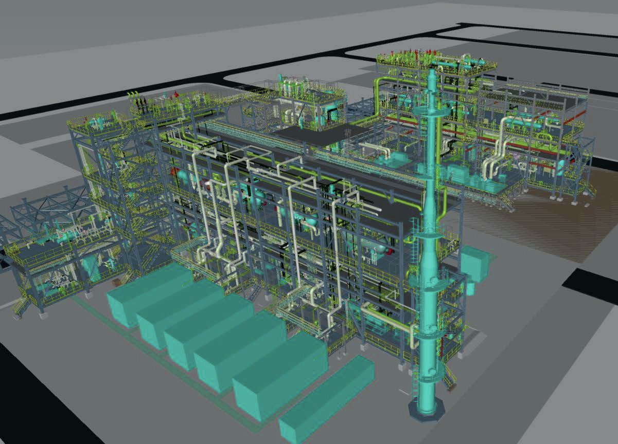
JM and Uhde announced their collaboration in May 2024 to integrate the LCH technology with uhde® ammonia process. Together this partnership offers world leading blue ammonia technology (Fig.8). This technology provides a competitive edge through use of the referenced flow sheet to provide rapid pay back through world scale plants, designed for exceptional efficiency, reliability, and performance to protect investment and drive down costs.

The Uhde loop design uses the high purity H2 and N2 provided from the upstream LCH technology and ASU in a dry low inert loop to operate without a continuous purge. This results in a more efficient process utilising the same equipment, which is already demonstrated to provide a capacity of over 3,500 t/d. Uhde provide industrially proven 2-bed and 3-bed converter designs (Fig. 9) that provide:
• high conversion rates through use of KATALCO™ catalyst with high surface area, whilst keeping the reactor volume small;
• maximum utilisation of reaction heat for the generation of high-pressure steam that is fully integrated with the upstream LCH technology;
• low-pressure drop, which calls for the use of small grain-size catalyst in Uhde’s radial-flow design of converter.

Uhde has over 130 reference plants. The higher capacities are typically achieved with dual pressure loop designs that have proven capacities of 3,670 t/d with in total more than accumulated 50 years operational experience. The same concept has allowed designs of over 5,000 t/d to be offered.
References for LCH technology
The LCH technology is a combination of mature, well proven unit operations which are already utilised in other JM technologies.
Its design offers project developers and operators industrially proven operating units, effectively integrated to enable production of low carbon hydrogen and ammonia at a large scale. Fig 10 shows some examples of the projects that have selected LCH technology to meet their needs for low carbon hydrogen production.