Sulphur 386 Jan-Feb 2020
31 January 2020
Refinery green fuel integration with a sulphur complex
RENEWABLE DIESEL
Refinery green fuel integration with a sulphur complex
M. van Son and S. Sreejit of Comprimo present a case study involving the design and potential integration of the sour water and acid gas treatment units for a renewable diesel facility with an existing refinery sulphur complex. The case study evaluates the potential for operating cost reduction by integrating an enrichment loop in the acid gas treatment plant as well as for using the existing infrastructure of the refinery to limit emissions.
The renewable diesel market has been growing and is driven by fluctuating oil prices, the mandates of governmental agencies to use renewable fuels and greenhouse gas reduction initiatives. In recent years, the integration of renewable diesel facilities with the existing infrastructure in refineries has proven lucrative and there are a number of projects in various phases of operation, engineering or construction. One common renewable diesel production process is via the hydrotreating of vegetable oils and/or grease, which produces a diesel product that can be blended with conventional diesel products from crude oils.
In order to achieve this, the hydrotreaters are operated with sulphided catalysts which limit the formation of Fatty Acid Methyl Ester (FAME), which can lead to problems with corrosion, blending with other diesel pools as well as stability and decomposition issues. As a result, many car manufacturers have limited the amount of FAME that can be present in the diesel used in automobiles.
In order to overcome the issues associated with FAME produced in transesterification technologies, new options have been developed to work with sulphided hydrotreating catalysts, which have proven to be able to produce higher quality diesel product that can be blended directly with the refining diesel pool. As typical green fuel feed stocks, such as rapeseed oil, soybean oil, vegetable oils or tallow contain very low concentrations of sulphur, it is essential to keep the hydrotreating catalyst sulphided and activated by supplying the unit with a sulphiding agent. This results in the formation of H 2 S as a product from the hydrotreating unit. In the scenario of the case study in this article, the original basis consisted of using DMDS as the sulphiding agent. However, upon further review, the potential to recycle the produced H 2 S was further considered as a means to reduce the DMDS consumption.
Project background
A green diesel facility is currently in design for a refinery in North America. The existing refinery has a sulphur complex that is used to process the sour water and rich amine streams that are produced in the refinery due to the processing of sour crudes which contain varying levels of nitrogen and sulphur. With the current typical limitations for the refinery products such as gasoline, jet fuel and diesel and the expected future limitations for bunker fuel after IMO 2020, these units typically are operated close to capacity with the final product being a waste water stream from the sour water stripper and elemental sulphur from the sulphur recovery unit. The scheme will typically include some kind of tail gas technology for the sulphur recovery unit to limit the SO 2 emissions from the stack.
During the initial phase of the project, the technology licensor had proposed a conventional sulphiding route for the sulphiding of the hydrotreating catalyst but offered an option to consider the installation of an acid gas enrichment scheme to be able to recycle produced H 2 S back to the hydrotreater. By employing this scheme, the consumption of sulphiding agent could be reduced substantially with a very short payout time of the additional investment cost associated with the enrichment of the acid gas and acid gas compressor.
A standalone sour water system was proposed as well, which handled the sour water from the hydrotreater. The sour water acid gas, which contained both ammonia and H 2 S was proposed to be processed in the new thermal oxidiser with a caustic scrubber installed downstream to meet the environmental regulatory requirements.
Initial design
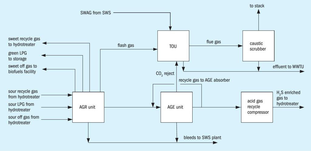
The initial basis for the project was to have a fully standalone installation for the green fuel facility, consisting of an acid gas enrichment scheme followed by an acid gas compressor with a sour water stripper to process the sour water. The proposed scheme had no interconnection with the existing sulphur complex. This appeared to simplify the design on paper, as there was no need for long piping crossing the boundaries of the facility as well as no requirement to evaluate the ability of the existing units to process the additional streams produced by the green fuel facility. In this scheme, a thermal oxidiser had to be installed to process the flash gas from the acid gas removal (AGR) unit, CO 2 gas from the enrichment unit as well as the sour water acid gas (SWAG) from the sour water stripper, where the H 2 S from these streams was converted to SO 2 .
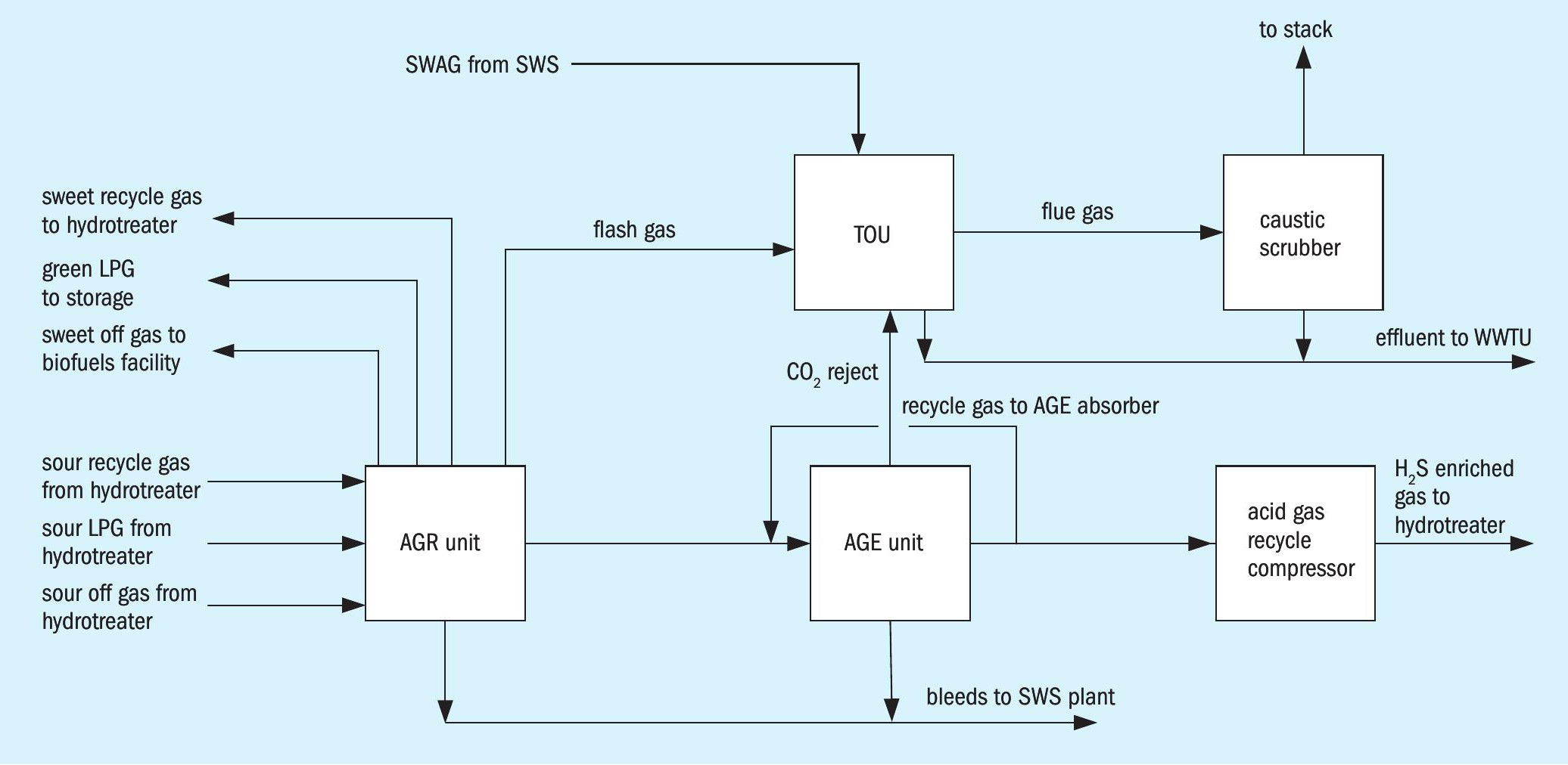
Due to the concentration of H 2 S in the CO 2 reject stream from the enrichment unit as well as in the sour water stripper acid gas, a caustic scrubber was considered for the flue gas from the thermal oxidiser to meet the environmental regulations.
Fig. 1 shows the original proposed line-up for acid gas treatment in the green fuel facility.
In order to recycle the acid gas into the hydrogen recycle loop of the hydrotreater, the acid gas, which was to be enriched to 60% H 2 S, will need to be compressed from about 12 psig (85 kPag) to 1100 psig (7590 kPag). Due to the very small volume of acid gas for this facility, a diaphragm compressor was selected.
Stripped water and spent caustic were intended to be routed to the existing waste water treatment facility associated with the site where the green fuel facility was to be installed, which was not directly connected to the refinery and sulphur complex.
Project hazard analysis
During the preliminary hazard analysis (PHA), the hazards of loss of containment on the high-pressure side of the compressor with a release of an acid gas stream containing 60% H 2 S was highlighted as a very high risk with a potential for a Level 6 event. As a result, the decision was made by the project team to re-assess the options for the project to limit the potential exposure to H 2 S as a result of the installation of an enrichment scheme with an acid gas compressor. This evaluation included the use of Process Hazard Analysis Software Tool (PHAST) software to determine the potential impact of a loss of containment associated with the acid gas enrichment unit as well as the installation of an acid gas compressor.
Configuration study
To determine the potential alternatives for the base case configuration, an evaluation of the options for handling the H 2 S produced by the green fuel facility was done. This included options to handle the sour water produced by the green fuel facility, as the base case considered the installation of an incinerator followed by a caustic scrubber to limit the environmental impact due to the presence of H 2 S and ammonia in the sour water stripper off gas.
Alternative configurations were evaluated based on the following considerations:
- Options with sour gas streams crossing over roads on public land were deemed unacceptable from past projects. Therefore, options with acid gas lines between the green fuel facility and the existing sulphur complex were eliminated
- The option to use the existing amine system of the existing refinery sulphur complex was eliminated due to issues with NH 3 and CO 2 forming salts in the lean amine, with potential for impacting the sweet gas specifications in the other absorbers. As well the existing amine regeneration system was already limited in capacity.
- The SWS location was deemed to be a cost optimisation potential and not technically limiting the evaluation of the risks associated with the acid gas recycle compressor and the alternative options for handling the sour gas streams.
Acid gas treatment
The purpose of the acid gas treatment (AGT) plant was to sweeten the recycle gas from the green fuel facility as well as the LPG and fuel gas streams produced in the associated gas plant. In the base case design, this was done by installing three absorbers in an acid gas recovery (AGR) system which used a primary amine selected to meet the required specifications for the recycle hydrogen, LPG and fuel gas. The acid gas produced in the regenerator of the AGR, which contained about 3.5% H 2 S, was then sent to an acid gas enrichment (AGE) unit, where with a proprietary amine, the acid gas was enriched to a concentration of 60% H 2 S.
This enrichment level minimised the recycle of CO 2 to the hydrotreater reactors and minimised the impact of recycling acid gas to the hydrotreater. As indicated above, the installation of a high-pressure acid gas line was deemed to have an elevated risk and other design schemes were considered.

Evaluation of SRU options
The alternative options to be considered were narrowed down to the following:
- Installation of an AGR/AGE option followed by a sulphur recovery unit:
- Installation of an AGE unit followed by a low sulphur removal technology:
– Selectox is a catalytic process which is similar to a conventional sulphur recovery unit, however does not have thermal stage due to the low H 2 S concentrations in the acid gas. The Selectox reactor, which contains an oxidation catalyst is followed by two conventional Claus stages. This process can operate with low concentration acid gases as no combustion has to be maintained in a thermal reactor.
– LO-CAT employs a liquid reduction-oxidation (redox) process that converts H 2 S to solid elemental sulphur, utilising an aqueous solution with proprietary blend of chemicals. Sulphur is recovered in a cake form with 60% solids content that can be disposed of in landfills. LO‐CAT technology has the ability to process lean acid gas streams and has several installations worldwide in similar applications.
– Thiopaq is a biological process for removal of H 2 S and is well suited to low tonnage low concentration acid gas streams. Sulphur is recovered in a cake form with 60% solids content that can be used in fertilizers or disposed of in landfills.
Comparison of the AGT options
The four options that were selected for further evaluation in comparison with the base case, were evaluated for the following parameters:
- operability;
- maintainability;
- reliability;
- capex;
- opex;
- process safety;
- SO 2 emissions;
- plot plan requirements;
- requirements for buildings;
- references for installation and consideration of technical feasibility.
In addition, the impact on the overall configuration of the AGT selection with respect to being able to meet environmental requirements needed to be considered together with the base case scenario where the sour water stripper unit was also installed in the green fuel area. With the installation of the sour water stripper, a small sour water acid gas stream containing NH 3 , CO 2 and H 2 S needed to be processed as well.
The economics of the base case configuration and the four alternatives were evaluated to determine both the capex and opex for each scenario. The relative cost comparison for the five options are provided in Fig. 2. As in the four alternative scenarios, the bulk of the operating cost was resulting from the DMDS supply that needed to replace the acid gas recycle, there was a very large premium in operating cost in the base case.
Selection of alternative AGT option
The installation of a sulphur recovery unit requires acid gas enrichment and therefore still has the risk associated with the high concentration acid gas stream. This process can handle SWAG, however due to the low sulphur recovery associated with a two-stage Claus unit will still require a caustic scrubber in the facility to meet the environmental requirements. It is also not efficient for low sulphur tonnages, particularly from a heat loss perspective.
The Selectox process will not require acid gas enrichment. This process cannot handle SWAG and therefore, this option would require a thermal oxidiser unit able to process ammonia from the sour water acid gas stream as well as a caustic scrubber. Similar to the Claus process, it is not preferred for its low efficiency for low sulphur tonnages.
The Thiopaq process does not require acid gas enrichment. This process cannot handle SWAG and therefore, this option would require a thermal oxidiser unit able to process ammonia from the sour water acid gas stream as well as a caustic scrubber. However, it is not as well established compared to the other processes and has very few installed units in similar applications.
The LO-CAT process was developed to treat low tonnage low concentration acid gases and has approximately 200 units worldwide. The process does not require the installation of acid gas enrichment and it has the capability to treat SWAG, even though the NH 3 will be present in the treated gas and will have to be routed to the thermal oxidiser unit. A caustic scrubber however may not be needed.
Based on evaluation and comparison of the four AGT configurations, the LO-CAT process, which is also the established industry leader for low sulphur tonnage processing with low concentration H 2 S feeds, was recommended as an alternative, if the acid gas recycle compressor option was not being pursued. Even though the capex was deemed to be the highest, all three other options evaluated were either deemed technically inferior for the low capacity of sulphur or insufficiently proven for requirements for this project.
Sour water stripping
Evaluation of SWS options
The sour water stripper has no impact on the selection of the acid gas treatment technology and was therefore initially excluded from the configuration study. The sour water stripper however does have an impact on the design of the thermal oxidiser unit (TOU) and as such the sour water stripper technology as well as the location of the sour water stripper and destination of the sour water stripper off gas were studied.
The sour water stripper options could be broken down into the following options:
- Locate a new sour water stripper in the green fuel facility and route the sour water stripper off gas to the thermal oxidiser (base case).
- Locate a new sour water stripper in the green fuel facility and route the sour water stripper off gas to the existing SRU of the refinery in the sulphur complex.
- Route the sour water from the green fuel facility to the existing sulphur complex and install a new sour water stripper there to process the existing sour water load from the refinery and the additional sour water from the green fuel facility. For this scenario, the collection of the sour water would still take place in the green fuel facility area.
- Install a new sour water concentrator in the green fuel facility and route the existing sour water stripper in the existing sulphur complex, where it can be treated with the refinery sour water and the sour water acid gas processed in the existing SRU.
Due to past experience with requesting regulatory approval for routing long acid gas lines between facilities, the option to route the SWAG to the existing sulphur complex was quickly eliminated. This left only two options – to install a new sour water stripper in the existing sulphur complex or install a sour water concentrator in the green fuel facility as options for further evaluation.
The existing sour water stripper in the sulphur complex had a design capacity that was insufficient to handle the additional water from the green fuel facility. In order to overcome this limitation, two options were considered. A new sour water stripper could be constructed in the sulphur complex that would be designed for the existing sour water capacity of the sulphur complex currently plus the green fuel facility sour water capacity with capacity built in to run off any built-up sour water storage. Alternatively, to be able to use the capacity of the existing sour water stripper, the sour water produced in the green fuel facility could be concentrated in a so-called sour water concentrator, resulting in approximately 90% reduction of the sour water routed to the sulphur complex.
In both scenarios, sour water piping with an estimate length of 600 m needed to be taken into account to be able to transport the sour water from the site where the green fuel facility was intended to be built and the existing sulphur complex. As the sulphur complex did not have a waste water treatment facility to process the stripped water, a return line was also required for the stripped water to the green fuel facility.
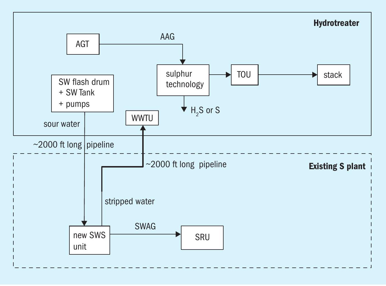
New sour water stripper
For the new sour water stripper, a similar design as opposed to the standalone green fuel area was considered with a higher capacity to be able to process the existing water produced in the refinery sulphur complex. The unit proposed was a single-stage sour water stripper with a pumparound system.
The installation of a new sour water stripper provided the following benefits to the project:
- Replacement of an old sour water stripper which was near to end of life.
- All sour water acid gas produced can be processed in the existing sulphur recovery unit.
- No sour water acid gas processing in the new green fuel area thermal oxidiser.
- No requirement for the installation of a caustic scrubber associated with the thermal oxidiser to meet emissions regulations.
- Elimination of additional waste stream due to elimination of caustic scrubber.
The following disadvantages for the installation of a new sour water stripper were determined:
- Limited plot space available to install the new sour water stripper.
- Demolition scope to remove existing sour water stripper.
- Limited ability to shut down the existing sour water stripper, resulting in potential difficulty to make tie-ins.
- Additional tie-ins are required to connect the existing sour water system with the new sour water stripper as well as with the acid gas lines to the SRU.
- Long sour water and stripped water lines crossing the battery limits of the sulphur complex and the green fuel area.
Fig. 3 shows the proposed configuration for the installation of a new sour water stripper in the existing refinery sulphur complex.
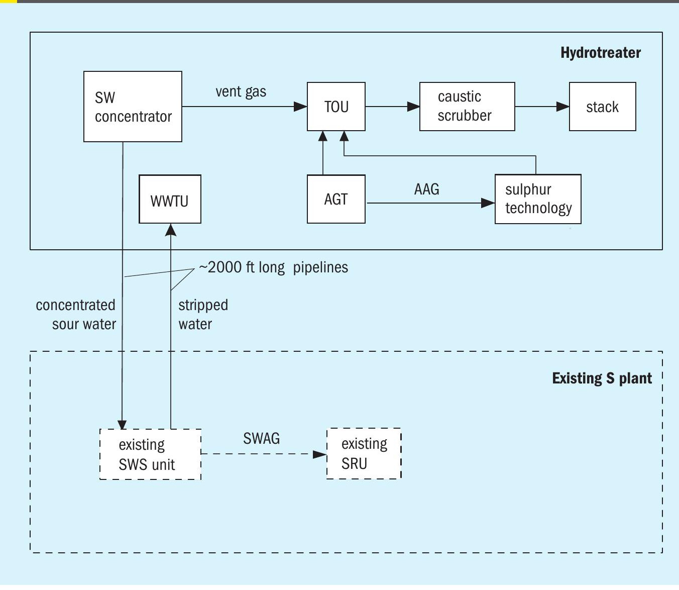
Sour water concentrator
A sour water concentrator is a non-refluxed tower in which most of the overhead from the stripping tower is condensed so that a small sour water stream remains that can be processed in an existing sour water stripper. As indicated earlier, it is typically possible to reduce the sour water rate to be processed by about 90%. Due to the presence of CO 2 in the sour water of a green fuel facility, a small off gas stream typically still remains which contains some H 2 S as well. This stream still requires processing in a thermal oxidiser.
The installation of a sour water concentrator provided the following benefits to the project:
- No replacement of the existing refinery sour water stripper required.
- All sour water acid gas produced can be processed in the existing sulphur recovery unit.
- No sour water acid gas processing in the thermal oxidiser
The following disadvantages for the installation of a new sour water stripper were determined:
- Similar plot space requirement as a new sour water stripper in the green fuel facility
- Additional tie-ins are required to connect the existing sour water system with the new sour water concentrator as well as with the acid gas lines to the SRU.
- Long sour water and stripped water lines crossing the battery limits of the sulphur complex and the green fuel facility areas.
Fig. 4 shows the propo sed configuration for the installation of a sour water concentrator in the green fuel facility, with the concentrated water processed in the existing refinery sour water
The option to process sour water acid gas in the thermal oxidiser requires the installation of special thermal oxidiser technology to handle the ammonia that is present in the gas. Ammonia destruction in a thermal oxidiser is typically considered difficult and requires special configurations to ensure that the ammonia is destroyed as well as the NOx formation is kept low. This can be achieved with higher than normal thermal oxidiser temperatures and implementation of staged combustion schemes for the introduction of the ammonia rich streams. In addition, there is a greater risk of the formation of SO 3 in these thermal oxidisers due to the higher temperatures and additional oxygen required for the combustion. Due to the environmental limitations of the location of the refinery, a caustic scrubber was required in all scenarios where sour water acid gas or even the vent stream from the sour water concentrator had to be sent to the thermal oxidiser.
Only in the scenario where the sour water was routed to a new sour water stripper located in the sulphur complex was it possible to eliminate the need for a caustic scrubber as the existing SRU had both capacity and tail gas technology that eliminated any additional SO 2 emissions associated with the green fuel facility installation.
Comparison of the SWS options
The relative capital costs associated with installing either a new SWS or a sour water concentrator in the green fuel facility or installing a new sour water stripper in the existing refinery sulphur complex are provided in Fig. 5. The relative cost includes the capital cost benefits of the elimination of the caustic scrubber.
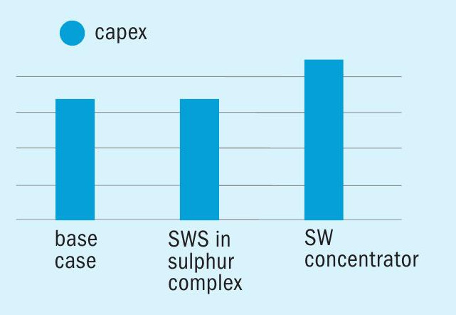
Selection of SWS option
All three SWS options considered are workable solutions. Even though installing a new SWS in the existing sulphur complex is approximately 30% higher in capex, it was recommended over the new sour water stripper or the concentrator option in the green fuel facility for the following main reasons:
- Better overall reliability, availability and maintainability due to a single processing unit versus a concentrator and SWS.
- Concentrator unit option will necessitate a caustic scrubber to be installed downstream of the thermal oxidiser unit for residual SO 2 removal, therefore also including a waste heat boiler.
- Requirement for a thermal oxidiser unit that is capable of destroying ammonia. The existing sulphur complex has had severe fouling issues with the processing of ammonia in the thermal oxidiser in the past.
- Concentrators are not commonly used for high CO 2 applications, due to vent gas which requires further treating for residual H 2 S removal.
- Lower overall opex for processing the sour water in the existing refinery sulphur complex.
By integrating the consequences of the presence of ammonia in the sour water acid gas with the options available for the acid gas treatment unit, it was concluded that substantial benefits could be expected by using the available SRU in the refinery sulphur complex. This resulted in simplification of the design of the thermal oxidiser as well as the need for a caustic scrubber to meet environmental requirements.
PHAST study
A PHAST (Process Hazard Analysis Software Tool) study was carried out to determine the dispersion scenarios in the event of loss of containment for pipe rupture scenarios for both the AGR as well as the AGR + AGE configurations. This also included the evaluation of the difference in consequence from the installation of an acid gas compressor and the potential risk that could be resulting from a leak.
The study was based on vulnerability, which includes factors like inventory, dynamics of the dispersion and duration of exposure for a leakage arising out of a 2” hole in the pipe.
The PHAST study indicated potential for exceeding H 2 S risks outside of an acceptable distance from the source of a leak. However, on further analysis, based on vendor information for the compressor, the risks associated with the installation of an acid gas compressor were better understood and the realistic risk was considered mitigable by appropriate design. The operating cost reduction due to the significantly lower sulphiding agent consumption was deemed sufficient incentive to improve the piping design as well as implement safeguards for the installation of the acid gas diaphragm compressor. The resulting reduction of sulphiding unloading frequency at the plant site was also a significant advantage to operations. Therefore, the project decided to proceed with the acid gas enrichment and acid gas compressor scheme.
Final recommendations
The project decided to proceed with the acid gas enrichment and acid gas compressor scheme. As for the installation of the sour water stripper, the recommendation was made to install a new sour water stripper in the existing sulphur complex with a capacity that was sufficient to handle the produced water in the sulphur complex as well as the additional water produced in the green fuel facility.
The benefit of being able to process the sour water acid gas in the existing sulphur recovery unit which was designed already to process this gas far outweighed the potential risks associated with handling SWAG in a thermal oxidiser.
By combining the selected option for the acid gas treatment with the installation of a new sour water stripper in the existing sulphur complex, the need for a caustic scrubber could be eliminated. This allows for the reduction of caustic consumption in the facility as well as reduced the impact on the waste water treatment.
By eliminating the caustic scrubber, a simple natural draft thermal oxidiser can be installed instead with no need for waste heat recovery, which was necessary for the caustic scrubber to reduce the inlet temperature into the scrubber.