Nitrogen+Syngas 363 Jan-Feb 2020
31 January 2020
Reforming catalyst under continuous development
PELLETED AND STRUCTURED REFORMING CATALYSTS
Reforming catalyst under continuous development
M. Wilson, J. Brightling and M. Carlsson of Johnson Matthey detail the development of steam reforming catalyst, with a focus on an operating case study, where Johnson Matthey has combined pelleted and structured reforming catalysts to deliver additional value from an existing asset.
Although the fundamentals of steam reforming chemistry remain the same, the operating conditions within a reformer are becoming more intense. The expected performance and life of a catalyst are increasing, resulting in demand for robust catalyst supports and formulations, capable of performance through the harsh reality of operating plants, with minimal loading variation and stresses, ability to cope with feedstock variation, shutdowns and steaming.
Building on knowledge and success of the KATALCO ™ ranges of ceramic supported catalyst, such as KATALCO 25and 57series, Johnson Matthey has invested in CATACEL SSR ™ technology, a metal foil based structured catalyst that delivers a dramatic improvement in the catalyst performance. CATACEL SSR technology allows previously unachievable combinations of heat transfer properties, reactive surface area and pressure drop characteristics within tubular steam reformers. These enhanced catalyst performance parameters can be tailored and targeted for each steam reforming plant such that maximum operational benefit is realised for existing plant operators or for those designing new steam reforming units.
Steam reforming catalyst developments
Steam reforming catalysts are for the most part made from shaped ceramic supports onto which the active nickel (Ni) species is impregnated and treated to give stable dispersed nickel oxide (NiO). There are a range of forming techniques and support formulations which all dictate both the chemical and mechanical properties of the final catalyst.

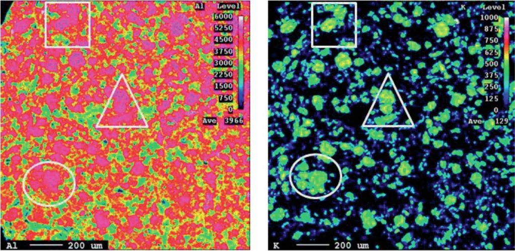
The chemical properties of the support and catalyst that need to be considered include stability in operation as well as transient conditions which include loading, start-up, shutdown and trip conditions. Looking closer at the role of the support, one important consideration in steam reforming is the propensity to form carbon. Carbon formation on the surface of a catalyst is affected by the surface acidity, as positively charged sites catalyse the cracking reaction and therefore increase the rate of carbon formation. Alpha alumina, a commonly used support, contains acidic sites. One way to make the surface less acidic is to add a compound of a group 2 metal such as Calcium (Ca), as seen in KATALCO 57-series. This modification of the support not only changes the surface acidity but also the mechanical properties, as well as the interaction between the surface and the Ni/NiO. This is important when considering that NiO has to be reduced in-situ to generate the Ni-metal sites which are active towards the steam reforming reaction. The support structure can be further modified to include dopants such as potassium (K), in KATALCO 25-series, which further enhances the carbon formation resistance of the catalyst by enabling faster gasification of carbon than its formation. Both for an unpromoted catalyst such as KATALCO 57-series and for a promoted catalyst such as KATALCO 25-series, it is important that the ceramic phases are stable in the extreme conditions which the steam reforming catalyst is exposed to. Under consideration are ensuring hydrothermal stability, minimising the sintering and phase change effect of steam on the support and also prevention of formation of inactive Ni-spinel phases. Looking closer at the KATALCO 25-series in the electron probe micro analysis (EPMA) image in Fig. 1, areas which are rich in Al (left image) and K (right image) are present, indicating potassium-aluminates which are there as potassium reservoirs for the catalyst. The use of a range of phases allows for the release of potassium at an appropriate rate under a range of process conditions and maintains high activity in terms of carbon removal.
The mechanical properties of the catalyst are a combination of the inherent material properties of the support together with its porosity, which are important to optimise for overall catalyst performance. Both the mechanical properties and the porosity are a function of formulation and manufacturing/forming technique and post-forming processing. With regard to the porosity, nitrogen gas sorption and mercury porosimetry are routinely used at Johnson Matthey to gain information on the pore structure/void space of both catalysts and adsorbents, measuring surface area, porosity, pore size distribution and inter-pore connectivity.
Each technique in isolation cannot give insight into the spatial distribution of the pore network. By integrating the two techniques however, scientists at Johnson Matthey have increased their understanding of the role of pore structure in reforming catalysts. Examining and analysing existing catalysts allows for the development of new catalysts with a pore structure that is designed for a particular application with optimum selectivity and activity. Designing a catalyst with small pores at a certain porosity will have the end result of a higher total surface area than an equivalent porosity with larger pores. Focusing on the diffusion limited reforming reaction, the optimised combination of pore volume and pore size and therefore surface area results in minimised diffusion limitations and maximised metal dispersion.
The mechanical strength of a catalyst pellet has been shown to be related to porosity and pore structure. The tensile strength decreases exponentially with the porosity, as shown by the Ryshkewitch-Duckworth equation:
ln ( σt ) = c 1 (D-1) σ0
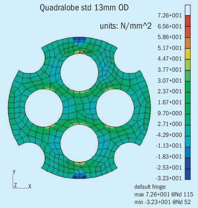
Where σt is the tensile strength, σ0 is the tensile strength of the material at full density i.e. zero porosity (D = 1) and c 1 is a constant related to the bonding capacity. Hence there is a direct tradeoff between overall porosity and physical strength. Generally ceramic catalysts will fail in tensile mode, where tensile stresses may be developed within the catalyst structure (as shown in Fig. 2). Whether or not crack propagation occurs through the porous substrate will be dependent on the porosity both with regards to size and connectivity.
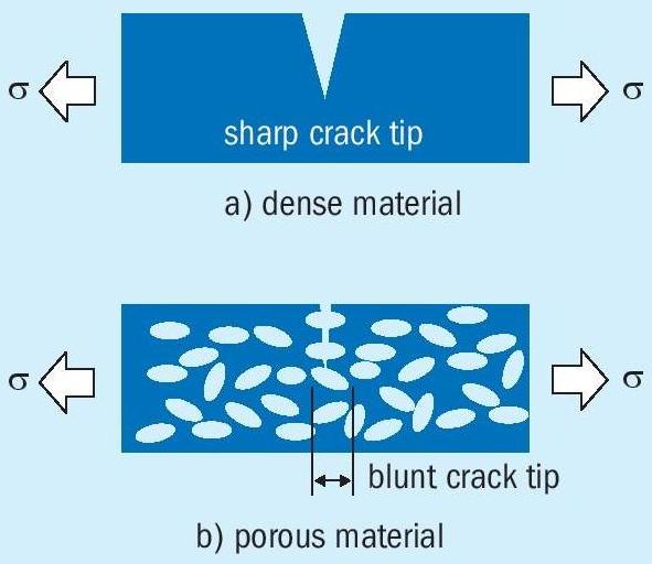
It is well understood in the field of material science and in particular crack mechanics that, ‘blunt crack’ tips have a higher threshold fracture toughness, as pictorially shown in Fig. 3, when a crack meets a pore the crack will become blunt which will decrease the stress concentration, potentially stopping it from propagating further, preventing breakage. Cracks with sharp tips propagate easier than cracks with blunt tips.
The strength of the catalyst must be high enough to allow loading through conventional means without breakage but still have sufficient porosity to maximise activity as detailed above.
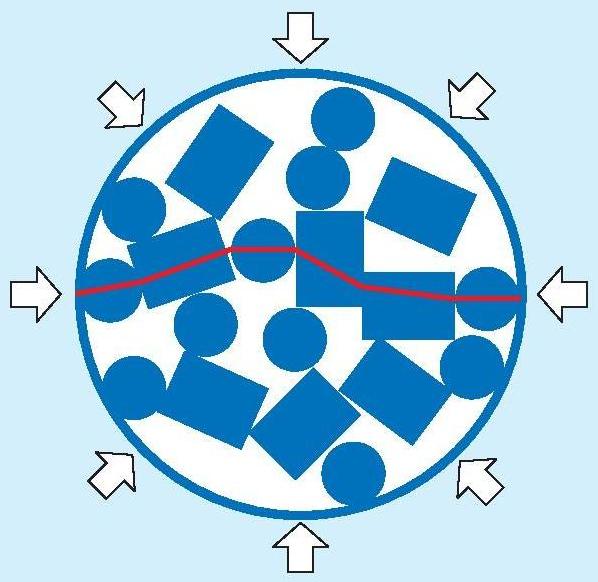
The final consideration with regards to mechanical properties of the catalyst is how it will break, as in some circumstances the catalyst will need to fail in such a way as to minimise pressure drop build-up. In a conventional steam reformer, this would be during a trip/shutdown when the tubes are allowed to cool down. As the tubes initially heat up, the associated thermal expansion leads to some settling of the catalyst. On subsequent cooling, there is insufficient rearrangement when the tubes contract to avoid stress chains to build up, as illustrated in Fig. 4.
These stress chains are a function of the packing structure of the catalyst, which is influenced by the catalyst’s external shape. The size of the fragments created during breakage to release this stress chain are a function of the catalyst shape as well as material properties.
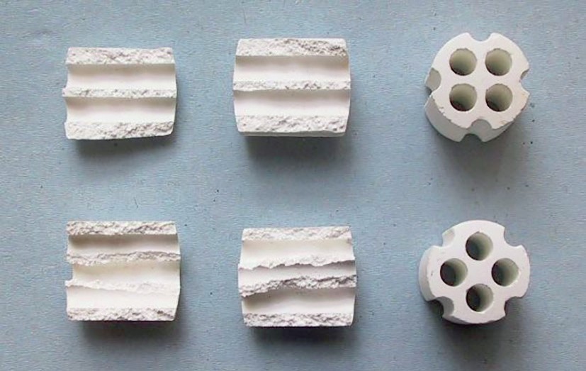
The KATALCO 57-series catalyst, a calcium aluminate supported catalyst, has been optimised taking all of these aspects into consideration. The calcium content increases the basicity of the surface to minimise carbon formation without introducing interactions that detrimentally affect the ease of reduction of the NiO. The porosity of the support has been optimised to have a bi-modal distribution of pores between 100 and 20,000 Ångtröms, ensuring a high surface area for dispersion on the active Ni, minimising diffusion resistance and giving a high mechanical strength. The KATALCO 57-Q series catalysts has been designed to break into large pieces, as shown in Fig. 5, which has as little detrimental effect on pressure drop as possible.
Alternative formulations with high strength and non-optimised porosity can lead to formation of many small fragments which would have a greater negative impact on the pressure drop over the lifetime of the catalyst. Similar detrimental effects would be present if the shape design was poor, for example having many external features which could interlock, facilitating build-up of stress chains. Alternatively, an intricate internal design can lead to many fragments being created when the pellets break.
Feedback from multiple users confirms that the robustness of the ceramic support in JM’s catalyst leads to less breakage of catalyst when loading. Additionally, the robustness of JM’s ceramic support is evident by the fact that JM catalysts are much more likely to display a lower rate of pressure rise over time. Many JM customers have experienced a change to a more favourable rate of pressure drop development, when they have switched to JM steam reforming catalyst from a competitive steam reforming pellet.
Metal foils and catalyst coatings
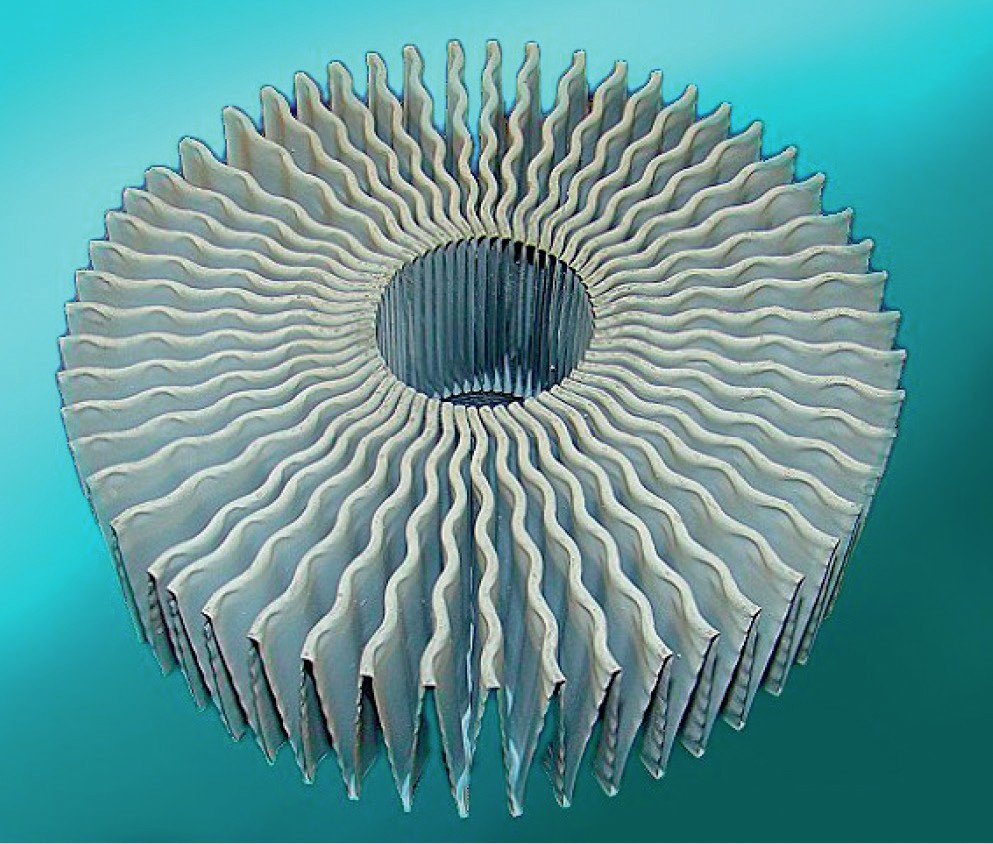
An alternative catalyst design to traditional randomly packed pellets is the use of coated metal foil technology, which has been shown to have several benefits, both with regards to catalyst design but also operation, one of which is the elimination of any breakage due to the stress chain phenomenon described above. Several high-quality metal alloys possess the combination of mechanical properties that allow them to be formed as thin metal foils and used as carriers for catalysts. These metal foils are light, extremely durable and can operate efficiently and robustly in very high temperature environments. CATACEL SSR technology uses a special high temperature alloy as a substrate material. Alloy strip is formed into engineered foil structures called fans (see Fig. 6).
A key factor in their success as a catalyst is the proprietary coating process that ensures that the catalytic coating is tough and long-lasting. The coating contains promoters that allow reduction and start-up on either natural gas or pre-reformed naphtha feeds with no special reduction procedure. The fans are coated with a nickel based steam reforming catalyst using a proprietary process that ensures the catalyst remains attached to the surface of the foil during the catalyst lifetime. The fans are stacked one upon another in the reforming tube, separated by thin metal washers.
There are a number of constituents of catalyst coating that are required to ensure that the binding of the coating to the metal foil is robust and durable. The preparation of catalysts by use of coating technology opens up the possibility of using a range of active catalyst components, stabilisation additives and other promoters that are not always feasible in more traditional catalyst systems.
Structured catalysts
A structured catalyst is a system in which the fundamental characteristics of a catalyst coated metal foil are used to design a precision engineered reaction media. The inherent and repeating structure that can be produced in such an engineered system ensures that the reacting gases within a tubular steam reformer are guided in a highly controlled flow path through the steam reforming reactor. This provides reproducibility of behaviour from tube to tube and allows the designers of these structures to engineer unique features with the structure that deliver high voidage, high geometric surface area and desirable patterns of gas flow.
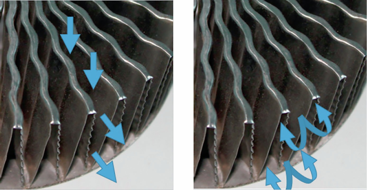
The stacked fans deliver superior heat transfer by impinging gas on the internal surface of the reforming tube rather than relying on convective heat transfer mechanisms. During operation, gas flows down the tube and encounters the first fan structure. It cannot move through the fan and therefore it is forced out of the triangular ducts. The process gas thus jets directly onto the internal surface of the reformer tube, where it gathers heat. Having nowhere else to go, the gas flows around the edges of the fan and back into the triangular duct on the underside of the fan (see Fig. 7). The washers that separate the fans from one another facilitate this flow back into the fan. Once inside the fan, the gas is free to move to the next fan in the stack and repeat the process.
Key features of CATACEL SSR technology
CATACEL SSR technology is designed to leverage the high voidage, high geometric surface area and controlled gas flow that is available in a structured catalyst system to gain the maximum possible process benefits within the unique environment of a tubular steam reformer. Hence, the low voidage of the CATACEL SSR structure provides the operator with an intrinsically low pressure drop reaction media and the high geometric surface area delivers a high activity steam reforming catalyst.
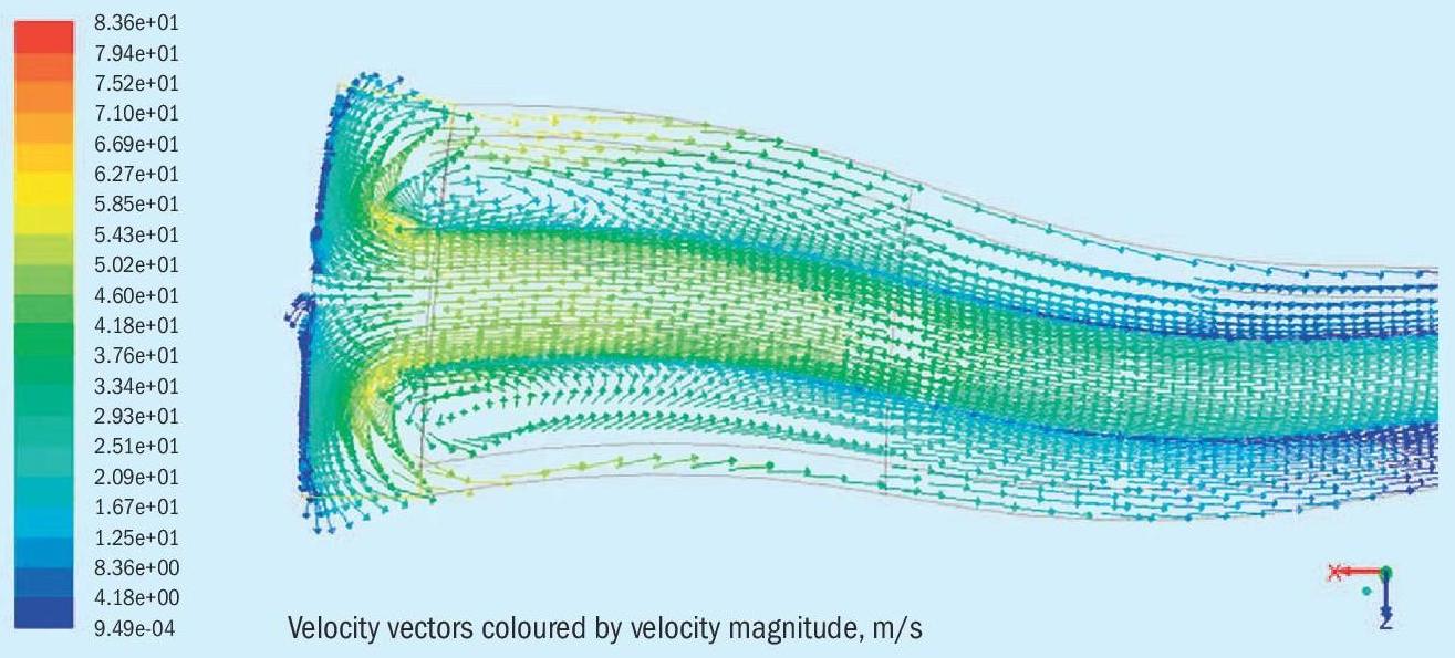
The outstanding design feature of CATACEL SSR technology is however the distinctive “fan” structure that is created by the precise manipulation of the underpinning metal foil. This feature carefully directs the gas flow in and through the CATACEL SSR structure and, most importantly, causes radial impingement of the gas onto the internal wall of the reformer tube. The “jetting” mechanism, as shown by CFD (Fig. 8) acts to destroy the stagnant, and heat transfer limiting, gas film that exists on the internal wall structure of the tubular reactors that are used in the steam reforming process. This “jetting” process repeats itself radially around the reformer tube and axially down the tube and it is this innovative behaviour that lifts the heat transfer characteristics of the CATACEL SSR technology to unsurpassed levels.
CATACEL SSR technology operational benefits
Heat transfer coefficients (HTCs) with CATACEL SSR technology can be 20-30% higher than those obtained with conventional ceramic pellets and with a lower pressure drop (PD). Furthermore, the fans offer a high geometric surface area, 1.5 to 2 times that of simple conventional pellets, and this is highly beneficial in areas where reaction is strongly pore-diffusion limited as activity is then proportional to surface area. The design of the fans can be tailored to achieve high heat transfer, high activity or low PD depending upon the requirements of individual plants and so can deliver maximum benefit in each case.
CATACEL SSR technology breaks the usual relationship that requires higher PD for improved thermal and catalytic performance, achieving far higher HTC and activity than is possible from ceramic based pellets while offering significantly lower PD.
CATACEL SSR technology produces a combination of high heat transfer, low pressure drop and high reactive surface area that cannot be achieved with any other catalyst system that is available in the industry. The technology is, within its field, highly disruptive and provides unique value and a basis for innovation for all operators and designers of steam reforming process technology.
Design flexibility
Every operating steam reformer is unique in respect of, for example, feed properties, reformer tube length, reformer tube metallurgy, reformer tube internal and external diameters, burner design, fuel composition, furnace size and furnace geometry. In order to optimise the economics of operation in such a system a great deal of design information and process data are required as inputs to complex programmes such as Johnson Matthey’s PRIMARY model. To date, suppliers have been able to deliver a limited range of catalysts that provide no more than binary changes in the factors that a process operator or designer can vary within these models when seeking to optimise performance. For example, small pellets such as KATALCO MQ have aided enhanced heat transfer but penalties may be encountered in respect of pressure drop. The patent protected fan structure can be designed and manufactured with a range of fan heights, with different densities of folds and with a variety of fine design features. These variables produce a vast combination of heat transfer, pressure drop and reactive surface area combinations that, when integrated with an understanding of the characteristics of each reformer unit, can be altered to maximise value for every reformer and every customer.
Impact on plant operation
Value creation comes from the enhanced heat transfer, larger reactive surface area and lower pressure drop characteristics of CATACEL SSR technology, which can deliver the most value to the operator of a hydrogen or syngas plant where a design or an operating process limit is constraining the efficiency or capacity. It is commonly found that CATACEL SSR technology can deliver:
Currently operating units
- 1%-2% throughput increases (direct replacement for standard pellets)
- 2%-10% trim fuel savings (direct replacement for standard pellets)
- 20% decrease in pressure drop compared to standard pellets
- Steam to Carbon decrease of 0.5 units (mol/mol) when replacing standard non-alkalised pellets
Revamps
- 10%-20% throughput increase with no change in tube wall temperature margin
- Tubes can be changed to lower cost, thinner wall, systems
- Decrease in tube count by 10% – 20%
- Decrease in tube wall thickness and or longer tubes
- 5%-20% lower capital cost of the radiant box
Case study: US Methanol plant
G2X Energy Pampa Fuels, a wholly owned subsidiary of Consolidated Energy Ltd. which is part of the Proman Group, owns and operates a nominal 185 t/d (22 million US gallons per year) methanol plant located in Pampa, Texas.
During a revamp of the plant, further development opportunities targeted the existing SMR unit, which included replacing the tubes in the reformer. JM worked with Pampa Fuels to review the potential to introduce new products that could be utilised to increase the capacity of the methanol plant. One such product was JM’s innovative reforming technology, CATACEL SSR.
CATACEL SSR technology breaks the usual relationship that requires higher pressure drop for improved thermal and catalytic performance, achieving far higher heat transfer coefficient (HTC) and activity than is possible from ceramic based pellets while offering significantly lower PD.
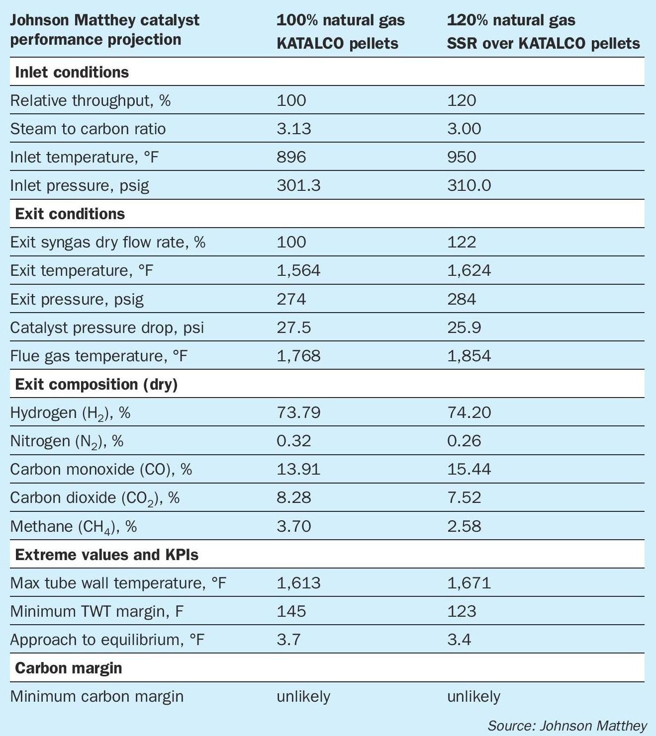
This combination of features presented Pampa Fuels with real opportunities for major improvements in the operation of the SMR, summarised below in Table 1:
- High HTC would reduce the tube wall temperature (TWT) and extract more heat from the combustion gases, leading to improved thermal efficiency of the reformer. The lower TWT would also increase the tube life.
- High activity would reduce the methane slip while further lowering the TWT. Further, the higher activity combined with the lower TWT would reduce the risk of carbon formation, with beneficial effects on the life of the catalyst.
- Low PD could yield benefits either through reduced load on the plant compressors or higher reformer (and therefore plant) throughput, the latter being the one of most interest.
Operating data
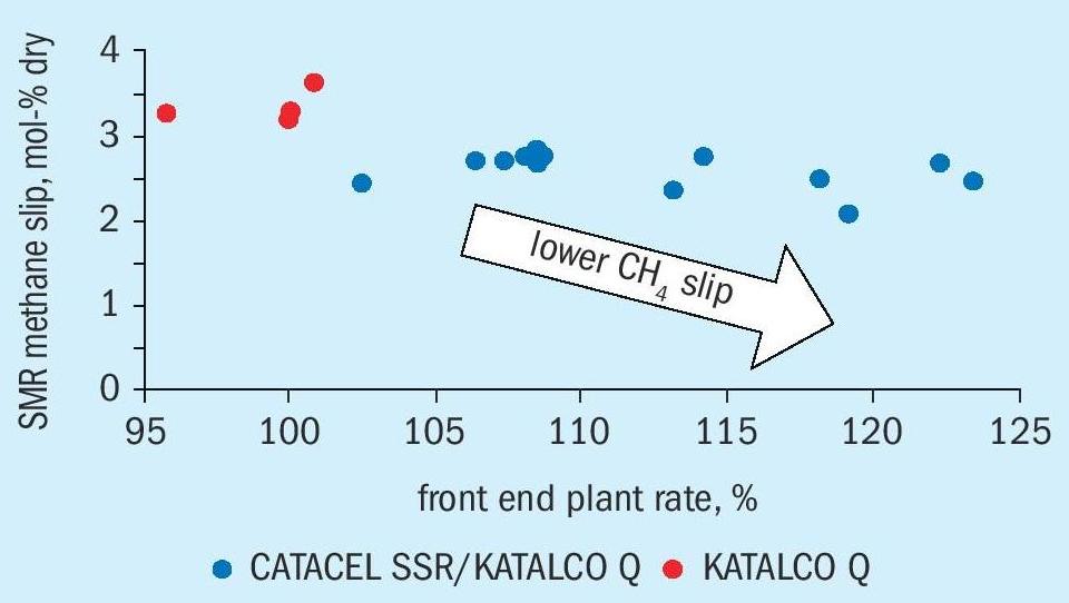
Since the plant uprate and restart in 2018, the newly installed catalysts in the reformer have delivered on the expected performance. Front end rate reached a peak of over 123%. The reformer methane slip as shown in Fig. 9, is trending lower, along with TWTs, as per expectations.
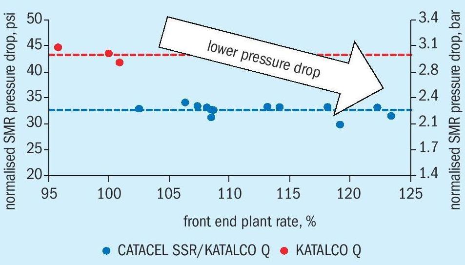
Fig. 10 shows the PD of the SMR (normalised to 100% rate) loaded with CATACEL SSR catalyst and KATALCO 57-Q series plotted against plant rate. Across a wide range of rates, the PD has displayed very steady performance. For comparison, results from the previous, full pellet charge of KATALCO Q-series are shown from various points throughout the catalyst life. The new catalytic combination has delivered improved reforming performance and a lower normalised PD.
Conclusion
Johnson Matthey has been pushing the boundaries of conventional pellet technology for many years, while also defining new and innovative structured catalyst solutions with CATACEL SSR technology. The combination of the very latest JM catalyst developments and plant equipment upgrades has led the G2X Energy Pampa Fuels facility to achieve a substantial increase in methanol production. Early performance has matched expectations and allowed the plant to operate at over 121% of the previous feed rate and deliver a proportional increase in methanol product. This is due to the low pressure drop of CATACEL SSR catalyst, used for the first time in conjunction with KATALCO Q-series pelleted catalyst, resulting in lower methane slip and greater process gas throughput.