Sulphur 387 Mar-Apr 2020
31 March 2020
Better monitoring and control in Claus plants
ANALYTICAL MEASUREMENT IN SRUS
Better monitoring and control in Claus plants
Applied Analytics discusses potential improvements made possible with data and analytical measurements fed into improved mathematical models to produce a more proactive approach to control and better performance of sulphur recovery units, AMETEK Process Instruments explains the benefits of feed forward control, SICK reports on reliable continuous emission monitoring systems and WIKA introduces a new purge-free system to measure refractory temperature in the Claus reaction furnace.
The control of a sulphur recovery Claus plant has been based on using simple concentration feedback for air demand control for the better part of the past 70 years. While the original British patent was issued in 1883, the Claus process was not implemented on a large scale until approximately 100 years ago and was using simple photometers since the 1960s to make measurements.
The importance of a sulphur recovery system has become an essential engineering control parameter in the modern world and more than likely will be progressed and expanded upon in the future. The continuing discovery and expansion of geologically abundant resources has led to the processing of a larger quantity of natural gas and crude oil of varying quality that potentially contains higher sulphur content. Sulphur recovery must be utilised to remove dangerous and toxic hydrogen sulphide (H2 S) and to limit sulphur emissions, primarily sulphur dioxide (SO2 ).
Improvements in monitoring equipment and process control sensors over time have resulted in increased efficiency and lower maintenance in sulphur recovery units (SRUs) versus their original process controls. Analysers were developed for properly determining the compositions of the feed gases and the acid gas inlet for H2 S content and impurities as well as instrumentation for temperature and pressure measurements prior to the reaction furnace burner. Analysers that monitor the Claus catalytic outlets for controlling the oxygen combustion air for maintaining the appropriate stoichiometric equilibrium in maximising sulphur recovery efficiency were also introduced. Improvements were made with flow equipment for monitoring reaction furnace residence time and sensors for catalytic converter bed temperatures and process reheating between stages. Monitoring of sulphur tail gas composition to tail gas clean-up units and subsequently monitoring the final emission outputs of the stack was implemented. With the introduction and implementation of better process instrumentation over time, sulphur recovery units now have better control, higher recovery efficiency, improved safety, reduced maintenance, and smoother plant start-up and shutdown. Even with the availability of all of these improvements in process instrumentation, operating and maintaining an efficient sulphur recovery unit is still a challenging task from a process control standpoint due to the complexity and magnitude of all the interlinked variables throughout process production.
Optimising a Claus plant
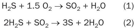
The combustion air feed rate is the most critical variable that affects the efficiency of a Claus plant. The combustion portion of any sulphur recovery unit is designed to produce enough SO2 from equation 1 to meet the required ratio from equation 2 of 2 moles of H2 S to every 1 mole of SO2 in the later catalytic and finishing sections.
Commonly, the air that supplies oxygen to the furnace in the Claus process is controlled by two valves in parallel, a main valve, and a trim valve. Ideally the trim valve is controlled using a tail gas analyser (H2 S, SO2 ) that is installed after the final reactor stage and before the incinerator, and the main valve is controlled using a feed forward basis that combines an H2 S analyser and acid gas flow rate. The tail gas analyser provides the ratio from equation 2 by measuring the H2 S and SO2 , which is used to control the trim valve.
Often plants forgo the feed forward analyser and rely on the tail gas analyser to control the air demand.
There are issues with this approach related to the dead time between tail gas readings and air introduction can be significant. Process modelling along with a feed forward analyser can help with this dead time issue.
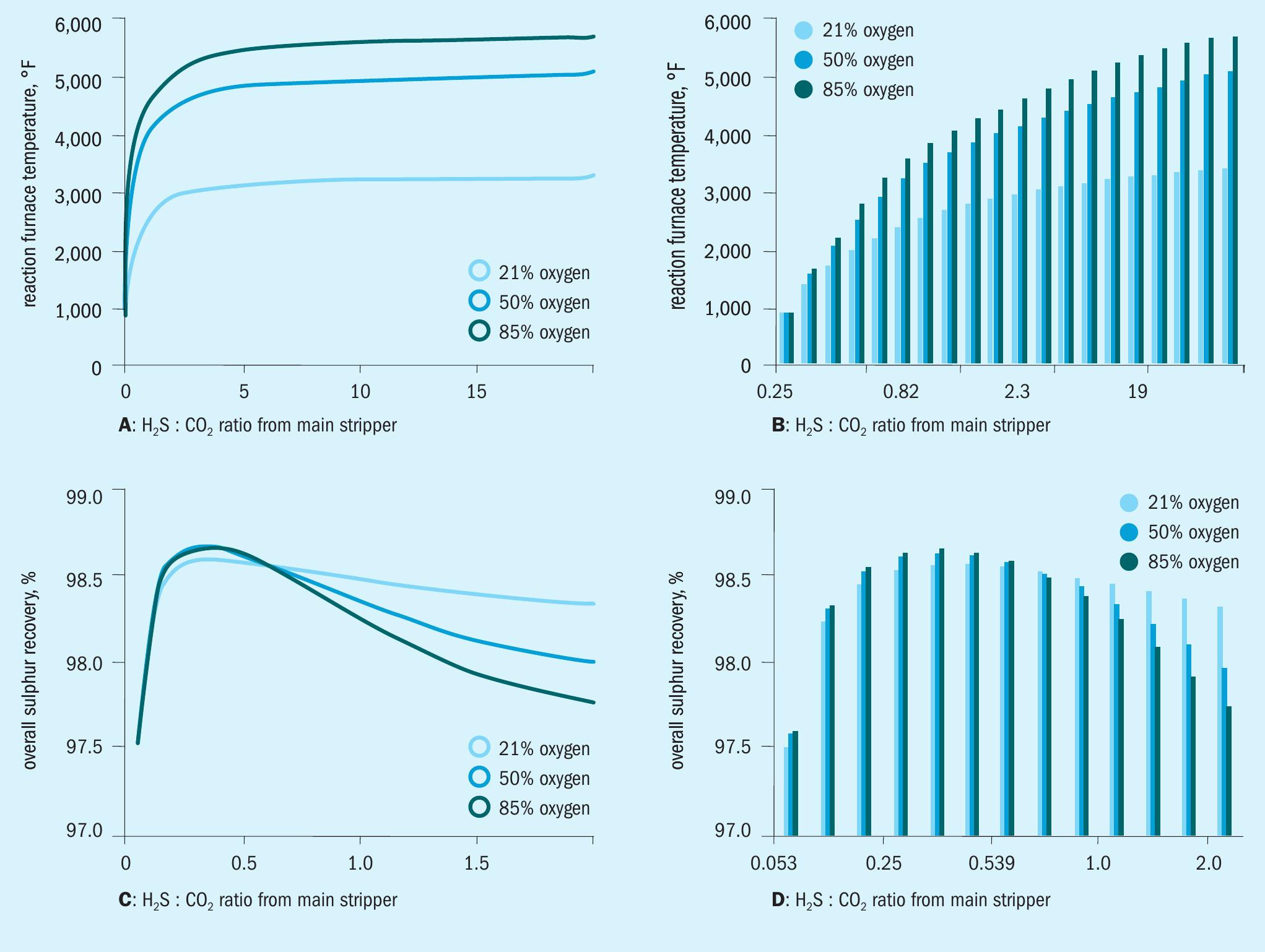
Carbon dioxide in the feed gas can also influence the efficiency of a Claus plant. High carbon dioxide levels can result in a severe drop in combustion chamber temperature. The higher the H2 S/CO2 ratio, the higher the combustion chamber temperature will be.
However, this does not correlate directly to an increase in efficiency. The relationship between H2 S/CO2 ratio and efficiency of sulphur recovery is depicted with a concave down (hill shape) graph (see Fig. 1) that has a maximum or ideal H2 S/CO2 ratio.
The ratio is typically controlled during the design phase by adding an acid gas enrichment process that selectively removes H2 S from the CO2 heavy stream, and then this upgraded gas is sent to the sulphur recovery unit. However, as mentioned earlier swings in the ratio have an effect on the temperature in the furnace and the ratio should be monitored at the inlet of the Claus plant to take pre-emptive actions to properly set the furnace temperature according to the incoming gas mixture.
Lean of peak, rich of peak
The H2 S/SO2 ratio in a typical Claus unit should be controlled as closely as possible to 2:1. However, there are instances that require different ratios, which come about in more complex Claus unit configurations. The first example would be when the sulphur recovery unit has a tail gas treatment unit. The tail gas treatment unit is affected by SO2 and precautions are taken to ensure that this component is not present after the catalytic stages of the sulphur recovery units. If there is even 12-12.3% excess air the tail gas treatment unit can completely fail. The pH of the system drops dramatically and the excess hydrogen can drop to zero. When a tail gas treatment unit is used in the plant design, the air demand is run on the lean side, which chokes the SO2 production and keeps a 4-5:1 ratio of H2 S/SO2 . A second example of running off peak is for SUPERCLAUS units. SUPERCLAUS units operate using the absolute value of H2 S as a point of control instead of the 2:1 ratio.
Efficiency improvement by feed forward control
SRU plants often process gas of unknown and fluctuating compositions coming from a variety of process units in a refinery. Feed forward control is key to handling these fluctuations.
One of the difficulties process analyser manufacturers face is the measurement of unknown process gas compositions. The other challenge is that the measurement must be very fast. The process gas needs to be measured right at the inlet of the Claus reaction furnace. The reaction time of the process gas in this reaction chamber is around three seconds, so any measurement taking longer becomes useless. In addition, ensuring the safety of refinery operating personnel is of paramount importance as the gases being measured can potentially contain up to 90% hydrogen sulphide (H2 S), one of the most toxic gases in a refinery. Having a simple, easy to understand and operate sampling system eliminates human errors and improves safety.
AMETEK Process Instruments has introduced a measuring system which meets these challenges, providing fast, reliable and safe measurement of process gas streams with unknown composition. End user feedback has confirmed its value with several users of this feed forward analyser reporting, “We decided to install this analyser in order to mitigate upsets of our SRU plant, in the beginning we were looking at the appearance of upsets, but now we have found the instrument is also useful for showing the disappearance of the upset condition as well”.
Process upsets
The TGTU operation of a sulphur plant depends on a smooth operating Modified Claus unit, but unless the SRU is handling a stable acid gas, e.g. in a small scale natural gas treatment plant, this is often not the case.
Unusual process conditions (upsets) are never welcome and shouldn’t be considered as “normal” but in daily life they happen, particularly when processing different acid gas streams or sour water stripper gas in the SRU. What is important is how well the situation can be controlled.
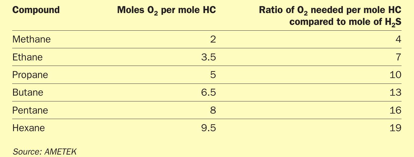
In some cases an upset may cause loss of recovery efficiency, resulting in higher emissions, which is undesirable but manageable, but in other cases, in addition to increased emissions, there may also be damage to process units. The latter can be caused by the breakthrough of hydrocarbons. Table 1 illustrates the impact of hydrocarbons on the air demand.
The higher oxygen consumption from the hydrocarbons will result in an air deficiency, which will be measured by the tail gas analyser and fed back to the process control system but only after a time delay (process lag time). Furthermore, the tail gas analyser only controls the trim air to the Claus reactor. If this is not enough, knowing about the condition of the upset will help.
Unfortunately, an accurate and component specific measurement is not possible in the required time. These measurements are only possible with the use of process gas chromatographs which take around 5+ minutes from the change of the process gas to any result of measurement (this includes sampling system). The upset may also be over before it is reported.
In the worst case scenario, hydrocarbon breakthrough, i.e. when there is insufficient air to burn the hydrocarbons, may lead to soot formation in the first catalytic reactor. Other consequences include loss of recovery efficiency leading to higher sulphur emissions.
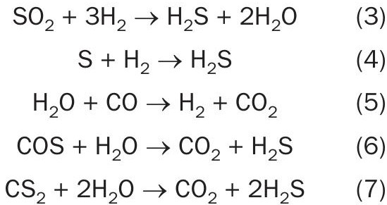
The TGTU will be forgiving and correct for the appearance of hydrocarbons. As an increase of hydrocarbons in the feed gas will lead to an air deficiency, the H2 S concentration in the tail gas will increase. However hydrocarbons can disappear as fast as they appear. The control system may have just managed to adjust the air flow to the reaction furnace so that everything is back to the required control set points but if the hydrocarbons then suddenly disappear there will be too much air fed to the reactor which will increase the SO2 concentration in the tail gas to unacceptable levels. The important question now is whether there is enough hydrogen available to hydrolyse all of the SO2 into H2 S. The following CoMo catalysed reactions take place in the reducing reactor:
Any SO2 breakthrough into the absorber tower will cause irreversible damage to the amine, which can be quite costly (costs of $40-50 per litre are not uncommon for specific amines). In this scenario, bypassing the absorber is the only option. There are two bypass options:
- bypassing the entire TGTU
- bypassing at quench tower outlet
Both options are illustrated in Fig. 2.
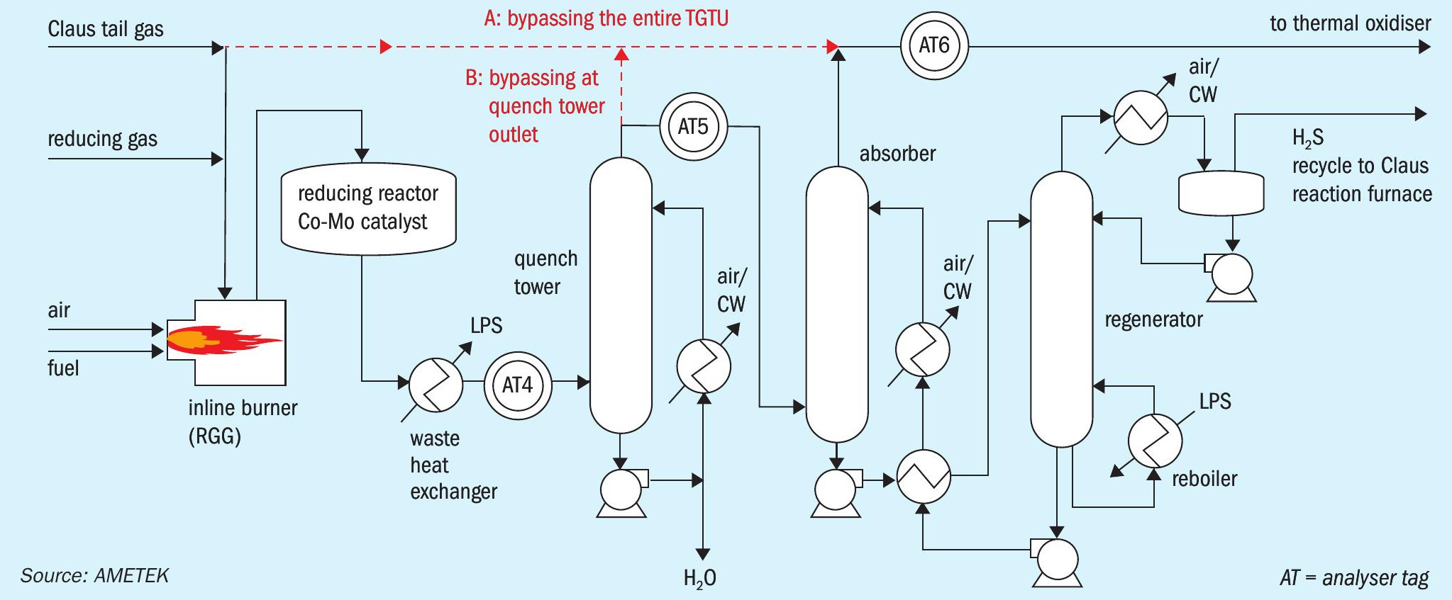
Process gas analysers (AT4, AT5 and AT6) can help to mitigate the worst case scenarios of 1) damage to the absorber amine and 2) bypassing the TGTU for an extended period of time.
In some plant setups both measurement options are utilised in the TGTU. AT4 monitors SO2 concentrations, to prevent damage to the amine found in the absorber. AT5 measures the H2 S concentration entering the absorber, to quantify the amine load required. AT6 measures the H2 S (and potentially COS and or CS2 ) concentration to assist in isolating operational problems and quantify contributions to sulphur emissions.
Recall that the reduction reactor in the TGTU converts all remaining sulphur components carried over from the modified Claus to H2 S, which is removed by the absorber and recycled to the Claus reaction furnace. In order for these reactions to take place, a reliable supply of hydrogen is required.
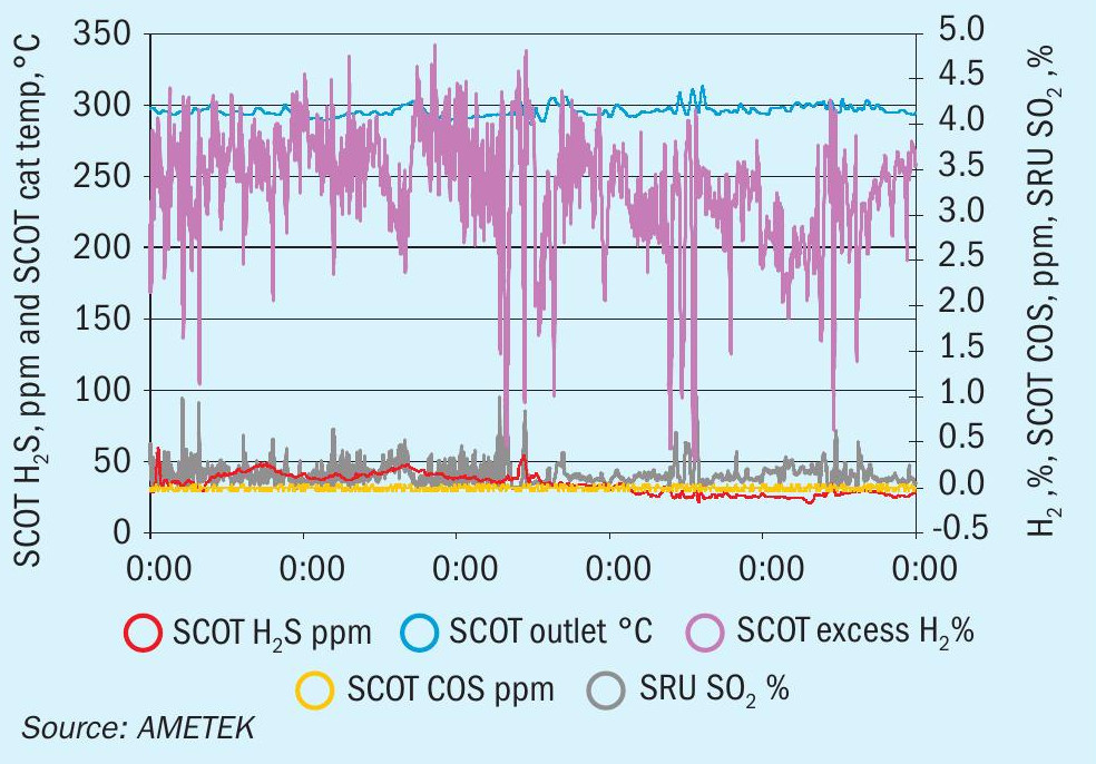
The graph in Fig. 3 shows the H2 reading as a function of an SO2 excursion. As soon as there is a deficiency of H2 , SO2 breakthrough becomes likely. Looking more closely at the reactions taking place in the reducing reactor (equations 3-7) it can be seen that every mole of sulphur also consumes one mole of hydrogen. As such, presence of SO2 at AT4 indicates that the hydrogen feed should be increased. Some users will monitor hydrogen at this point (or at AT5 or AT6), to identify whether or not too much hydrogen is being injected.
Proper selection, installation and operation of process analysers can reduce emissions, safety risks and operational costs in SRUs.
SRUs have historically been complex to operate because of the varying make-up of the feed gas streams and the multiple thermal and chemical processes used to remove elemental sulphur, but AMETEK analytic solutions continue to reduce that.
Artificial intelligence – a proactive approach to control
Applied Analytics is looking into adding more measurements upstream of the thermal reaction furnace (i.e. H2 S/CO2 in acid gas, H2 S in amine, H2 S in sour gas inlet) and incorporating those measurements along with other plant specific data into robust mathematical models to yield a more efficient and predicable sulphur recovery unit.
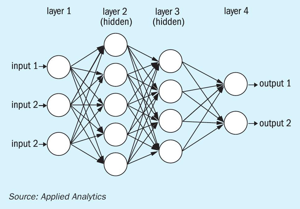
The basis behind the artificial intelligence (AI) in a plant is that the system would take in a series of inputs (in this case this would be the process data at all the different analyser and instrument points) through an adaptive program to learn and optimise the process. AI uses what is called a neural network (Fig. 4) which is a computational approximation of how the mind works. The neural network is built through the interaction of nodes. The data comes in and is run into the first layer, layer 1. The data gets combined into a series of nodes in hidden layers shown below as layers 2 and 3. Each of the nodes in the hidden layers performs a function with the data and then passes the new data forward. Once the information is translated through the hidden layers the data is compiled again into an output. In this case the outputs would be adapted set points for the system. There can be a multitude of hidden layers depending on the required results. Using learning algorithms allows for the system itself to adapt based on the results, changing the parameters of the nodes as the system is running to optimise performance. As can be seen by the system in Fig. 4 even with as few as three inputs the system is making a vast number of connections between the data and building out correlations based on this. A system built like this would be tuned to the specific process and the system would be able to adapt to the changes in that system.
Using this technology would allow the creators of the AI to build in certain parameters in which the AI would be able to run, ensuring that the process changes were not overcompensated for during the onset period while the system is learning or by erroneous reading. This could also force the system into only running in known safe run areas for the sulphur recovery unit. Using all the data that the system collects the AI could act as both a control unit for running the plant and it could also create an overview of how the plant is functioning, detecting issues long before they become problems. This has the potential of both giving invaluable information on how the plant is running and maintenance that needs to be done before it affects the product of the system or the run time.
The recent push for sulphur recovery plants to release less sulphur and the regulations that are being put in place make sulphur recovery a prime candidate for AI modifications. Many of the factors in the Claus plant affect the efficiency of the sulphur recovery unit. The main factor as mentioned above is the H2 S and SO2 ratio.
This ratio is most generally determined by the ratio of oxygen to the acid gas that is allowed into the reaction chamber, however there are many other factors that affect this reaction. Side products are often formed in the reaction chamber and beyond creating unwanted products their presence can alter the expected stoichiometry of the reaction and that of the downstream reactions. Additional hydrocarbons or CO2 in the feed can upset the burn temperature leading to more side reactions or react with and use up the oxygen meant for converting the H2 S to SO2 . These reactions are dependent on the temperatures in the chamber, fluid dynamics (mixing), heat transfer, along with the composition of the feed streams at the entrance to the reaction chamber.
Current modelling software is not able to perfectly predict the outcome of this reaction as there are many reactions that are taking place. Most models focus on just the few reactions below or fewer, however some of the more comprehensive models can have thousands of assumed reactions happening in the chamber. Modelling these though a kinetic model has shown to be the most closely correlated to the actual results seen in the plant. Even this is not a perfect simulation and has its inaccuracies, particularly around some of the side reactions. Additionally, the process is not always constant and can change based on a variety of factors like the feed composition into the reaction chamber and the mixing of the air and acid gas. Since each feed stream is different and the plants are not designed identically there has yet to be a model created that can fully describe every process and predict the outcomes and changes during the systems run time well enough to fully optimise the systems. Some adaptive kinetic models have shown promise on running sulphur recovery units in stabilising out the systems and reducing spikes in H2 S/ SO2 ratio. These systems are the first steps of AI implementation in sulphur plants.
Like much of chemical engineering, AI builds out models based on the data collected from process runs. This data is then compiled and the system uses this data to more tightly control the system. Feeding as much information to that AI as possible will allow it to make process adjustments to optimise the reactions in the plant based on how the specific plant itself is running. Instruments around the reaction chamber such as temperature, pressure, and flow analysers along with the compositional data from the acid gas analyser and the tail gas analyser will allow the AI to react quickly to changes seen. Adding analysers at the inlet of the process before the amine towers and on the rich and lean amine streams is always a good idea as it gives even more information allowing the user to predict how the process will react before the gas gets to the acid gas analyser. Adding these analysers to the AI inputs allows the AI to track how concentrations on the front end and the condition of the amine affect how the amine towers are working and adjust for the changing feed into the reaction chamber faster before it reaches the feed.
Commonly, the main (and sometimes only) analyser feedback used is the tail gas analyser. Since it is on the end of the process this analyser can have a 3-minute lag or more after the gas enters the system making the system reactive rather than proactive. If the tail gas analyser is coupled with feed forward analysers, the process becomes much more predictive. After adding these analysers, the AI takes all the data across the process, which can include the massive amount of data that is now stored by the DCS of trends over the past years and fills in the neural network based on the programmer’s instructions. This network would be used to determine the best settings for the specific reactor in the specific plant incorporating the analyser response times and the process lag time between changes and when the process reacts. Process controls based on these parameters will be predictive and changes consider all the available information to keep the system running at peak performance.
In addition to the increased efficiency and performance, this would also allow for the operators to only do required maintenance when it is needed, as opposed to during manufacturer recommend maintenance schedules. Doing this decreases the amount of time and money invested into the process. Through this and the AI modelling all these systems allow for the process to run more efficiently adding value to the customer through the predictive analytics which decreases upsets and ensures the plant is running at peak performance.
Reliable CEM systems for sulphur recovery units
Monitoring the flue gases exiting the final stack of the SRU is a legislative requirement and places unique challenges on the continuous emission monitoring (CEM) system.
Emission limit values for compliance are stated as normalised concentrations, i.e. referenced to 1,013 mbar, 0°C, dry basis (0 vol-% water vapour) and typically normalised to a given oxygen concentration (3 vol-% O2 ). Therefore, as well as the prescribed pollutants such as SO2 , NOx and CO, the emission monitoring system should additionally measure oxygen and unless measured dry basis, also water vapour.
Conventional cold dry extractive CEMS design
CEM systems for the purpose of measuring and reporting flue gas emissions behind a conventional combustion process have historically employed a cold extractive gas analyser. This CEMS design is based around pre-filtering an extracted sample gas to remove particles and then drying the gas by passing it through a refrigerating cooler (operating at 2-5°C) to condense out the water vapour, which is then removed. The dried sample gas flows via a sample pump to the non-dispersive infra-red (NDIR) gas analyser, which simultaneously measures SO2 , NO and CO by means of quantifying the amount of infra-red light absorbed at wavelengths specific to these different gases.
An additional paramagnetic oxygen detector module serves to allow the pollutant concentrations to be “normalised” to the oxygen concentration at which the pollutant emission limit values (ELV) are referred to. However, the particular sample gas properties found in the flue gas behind the SRU thermal oxidiser present significant difficulties when considering the application of this classical CEM system design.
First and foremost, the presence of elemental sulphur in the background gas is a major deterrent to utilising a sampling method which is based around chilling the sample gas to remove water. Cooling a sample gas containing elemental sulphur will result in solid and liquid sulphur blocking the sample system. Contamination in the sample cell can have fatal consequences.
Similar issues surround the cooling of any sample gas containing significant concentrations of sulphur trioxide (SO3 ), which once below its acid dew point and if not removed with 100% efficiency can cause significant corrosion problems, especially to the sensitive, gold-coated gas analyser sample cell.
Finally, representative measurement of low SO2 concentrations is compromised when the drying method creates water droplets, which prior to removal are in contact with the gaseous water-soluble SO2 molecules.
For these combined reasons, the conventional cold, dry extractive gas analysis system is entirely unsuited to the application challenges of SRU continuous emission monitoring. Fig. 5 shows an optical window of a measuring cell fatally contaminated by elemental sulphur.
Hot wet extractive CEMS design
In recent years, the hot wet extractive analyser has been employed as the basis to continuously measure and report emissions behind the sulphur recovery unit. It has proven itself to be far better-suited in comparison to the conventional cold extractive analyser.
This analyser design is known as “hot wet extractive”, because rather than cooling the extracted sample gas to remove water as a means to dry the sample gas, the sample gas is kept at a high temperature well above its dew point temperature and as such, the pollutant concentrations are measured in a “hot, wet” condition.
This design requires all elements of the gas analysis system, i.e. sample gas extraction probe, heated sample gas line and gas analyser to be thermostatically controlled at a temperature of 180-200°C. Since water vapour is not removed, it must be measured, both to dynamically correct for its cross-senstitive effect on other gases and secondly to enable pollutant concentrations to be expressed, dry basis.
The measurement principle is based on the absorption of infra-red light characteristic to pollutant species. The hot extractive gas analyser has a multi-component capability. A single hot extractive gas analyser can continuously measure SO2 , NO, NO2 , CO, H2 O, CO2 and O2 . The oxygen measurement for normalisation purposes is achieved by integrating an extractive ZrO2 sensor within the heated measuring section of the analyser.
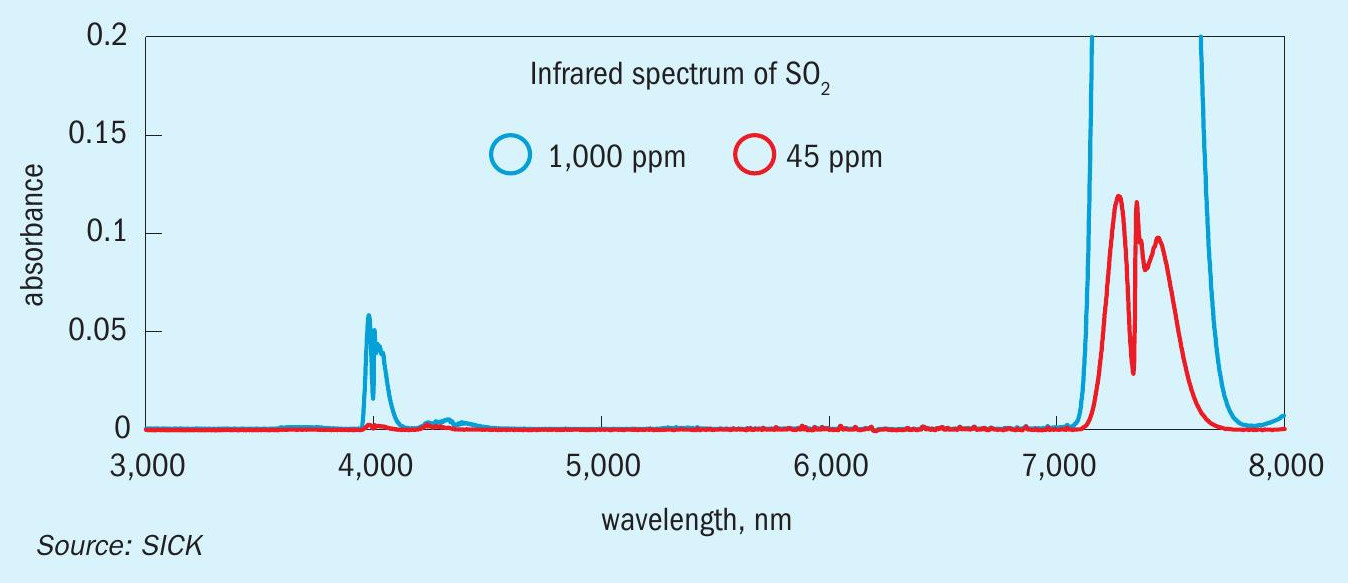
The design principle of the analyser allows it to be configured to measure widely varying flue gas concentrations as a function of rapidly changing process conditions. For steady state conditions, the primary SO 2 range might be 0-300 ppm. However, the analyser can be configured with a secondary SO 2 range, for example 0-8,500 ppm SO 2 . This ensures that the analyser measures SO 2 with optimum uncertainty regardless of whether very low SO 2 concentrations are prevalent during typical steady-state conditions, or when several thousand ppms SO 2 are present during TGTU bypass. Fig. 6 shows the SO 2 wavelength selection with respect to target gas concentration.
A new version of the hot extractive analyser, MCS 200 HW, manufactured by SICK AG has recently been certified by testing authorities in both Germany (TUEV Rheinland) & UK (MCERTS) for the purpose of continuous emission monitoring according to European regulation EN 15267.
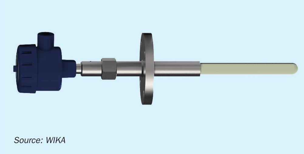
Purge-free refractory temperature measurement
In a Claus unit, it is important to measure the refractory temperature to make sure it does not exceed refractory limits. Thermocouple sensors and pyrometers are used to monitor the refractory temperature.
Type S thermocouples (see Fig. 7) are typically used since they basically show no aging up to temperatures of 1,400°C. They are also an excellent candidate because they can work well in a reducing or inert atmosphere. The downside of a Type S thermocouple is that it is susceptible to contamination and hydrogen will cause the wires to become brittle. Both phenomena will cause the thermocouple to fail.
Until now, the basic solution to this was to purge the thermocouple. By doing a purge, the gases and hydrogen are swept away from the thermocouple itself. The problem with a purge is twofold:
- A purge is considered a high maintenance item. If you have a purge system you must monitor it to make sure the flow rate is correct and that all components are operating correctly. There is a cost to get the purge system installed and to have a constant use of gas, which should be nitrogen but is often air.
- The flow rate must be set properly. If it is too low or there is loss of purge, the thermocouple will become contaminated and break. If the purge is too high, the thermocouple reading will be lower, giving a false sense of comfort.
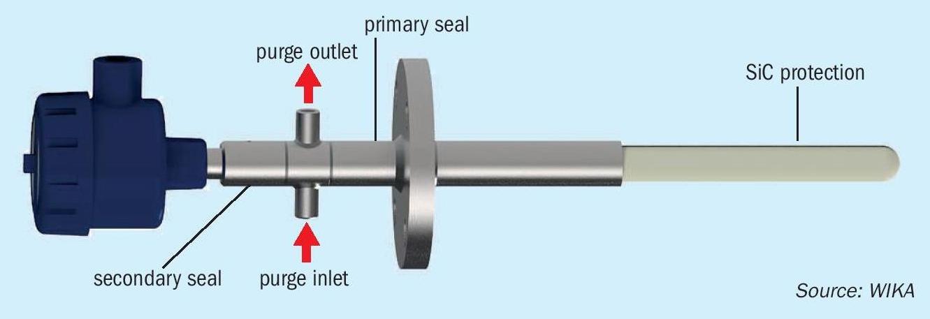
WIKA has a totally different method for reliable temperature measurement of refractory in Claus units that can be realised without the installation and challenge of maintaining a purge.
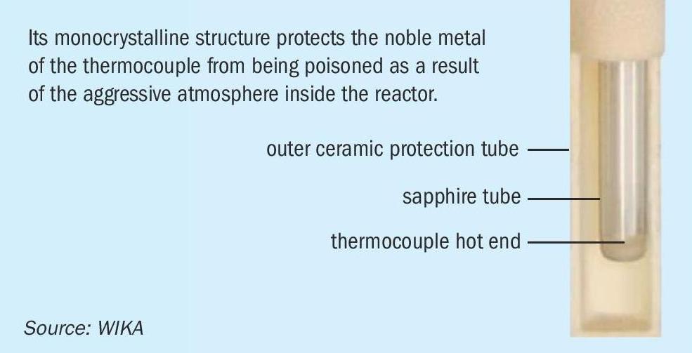
WIKA purchased a company that produced a system using a monocrystal sapphire (Fig. 8), which has been used in gasifiers in the GTL industry. Its monocrystalline structure protects the noble metal of the thermocouple from being poisoned as a result of the aggressive atmosphere inside the reactor. This solution has been used successfully in different reactors worldwide since 1997 under the designation model T-FZV. Pressure-tight, hermetically sealed junctions between the sapphire and metal protection tube, and also a multifold sealing system in the connection housing prevents toxic gases from being able to escape the reactor (Fig. 9).
This solution has also been installed and used in a couple of Claus units in Europe. The first one has been running for over six years and continues to operate today. The second one was installed almost three years ago and the customer reports that they will be installing the WIKA Sapphire solution (Fig. 9) on the other Claus unit during the next turnaround.
The key to this success is the monocrystalline sapphire, which can dramatically slow down hydrogen migration. There have been attempts to use just sapphire, but the crystalline structure allows for hydrogen to migrate. It is also important that the design of the unit remains sealed in case of breakage. There are things that can be done to minimise breakage due to refractory shift, but gas should not escape the system into the atmosphere.Another increasing concern nowadays is how to monitor if there is a catastrophic loss of the refractory. Wika is currently conducting research within its new state-of-the-art research furnace and reactor to test different methods, including fibre optics, magnet thermocouples, washer thermocouples, and other designs.
References