

Nitrogen+Syngas 364 Mar-Apr 2020
31 March 2020
Evolution of a new NH3 synthesis catalyst
AMMONIA SYNTHESIS CATALYST
Evolution of a new NH3 synthesis catalyst
AmoMax ® -Casale is a new ammonia synthesis catalyst jointly developed by Casale and Clariant. Retaining the same superior resistance to ageing, poisoning and mechanical strength as the well-known wustite-based catalyst, AmoMax ® 10, the new catalyst is significantly more active. C. Berchthold of Clariant and S. Panza of Casale explain the advantages of AmoMax ® -Casale and share the start-up experience of the first commercial reference.
Catalyst development
Catalytic ammonia synthesis from hydrogen and nitrogen represents one of the most important industrial reactions today. The catalyst used in this reaction is made from iron oxide with small amounts of other oxides added as promoters to enhance activity and stability. Despite the Haber-Bosch process being more than 100 years old, only incremental improvements have been achieved until recently. Combining the catalyst expertise of Clariant and the engineering knowledge of Casale, a breakthrough has been realised leading to the new ammonia synthesis catalyst AmoMax ® -Casale.
The new catalyst is based on Clariant’s successful catalyst AmoMax 10 with more than 100 references worldwide and is customised for Casale reactors (patent pending) with significantly improved activity compared to state-of-the-art iron-based catalysts. When introducing a new catalyst to the market, performance evaluation is of utmost importance. Simple catalytic tests in powder form are not representative enough for industrial applications and are only suitable for screening purposes. Therefore, a precise and rigorous methodology must be applied.
Materials and methods
To reliably validate a new catalyst, laboratory-scale tests should be representative of the industrial catalyst. Thus, catalytic and mechanical tests are performed with the final form and shape of the catalyst. During catalytic tests, the temperature profile in the catalyst bed is measured and correlated with the heat exchange between oven and reactor. Subsequently, systematic modelling of the obtained data is applied to understand the performance of the catalyst under industrial conditions. The information acquired is used to compare the new catalyst with the best available state-of-the-art catalyst technology. In case of the superior activity of the new catalyst, as a next step, in-depth mechanical stability characterisations are performed to confirm the robustness of the catalyst. This includes simulations and experiments of friction between the catalyst pellets/granules and the walls of the reactor, crush strength and simulations of startup/shut-down of industrial reactors. If the catalyst passes all the mechanical tests, proof of concept is achieved, and it is considered ready for scale-up. Transferring the catalyst recipe from lab to production scale is a highly complex process with numerous important parameters, which must be considered by the catalyst manufacturer. After a successful scale-up, the catalyst is prepared for shipment. To ensure it maintains its mechanical integrity and activity after transport from the production site to the plant, samples are taken during transportation, sent to different analytical laboratories and precisely analysed. The catalyst is then validated with the same catalytic and mechanical tests applied during the proof of concept phase. If all parameters are confirmed, the catalyst is finally ready for the market.
Performance tests
Activity
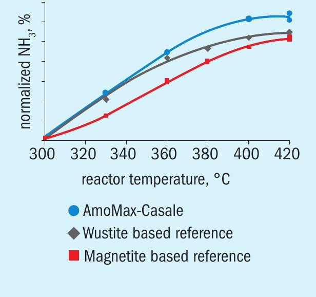
Laboratory results for the catalytic activity are reported in Fig. 1. The test conditions were:
- Tubular reactor, tests performed on granules
- Pressure: 150 bar and H 2 : N 2 = 3
- Temperature: 300, 330, 360, 380, 400 and 420°C
The results show how the new AmoMax ® -Casale outperforms magnetite and wustitebased state-of-the-art ammonia synthesis catalysts over the whole relevant temperature range. In particular, the gap between AmoMax® -Casale and standard magnetite catalyst is drastically increased.
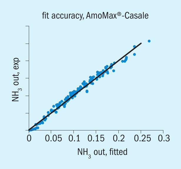
Based on the test results a kinetic model was created which fits very well with the experimental data (see Fig. 2).
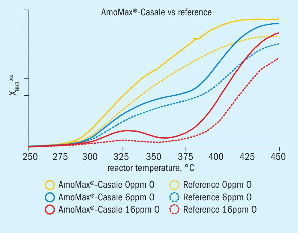
Poison resistance
The performance with different O2 concentrations in the feed was tested at different temperatures with the following results:
- The oxygen poisoning behaviour of the new catalyst is similar to the reference catalyst at all measured O2 concentrations (compare dotted versus full line)
- The deactivation observed due to oxygen poisoning corresponds to observations in commercial plants.
- Despite the higher activity, AmoMax® -Casale offers superior performance regardless of oxygen concentration (Fig. 3).
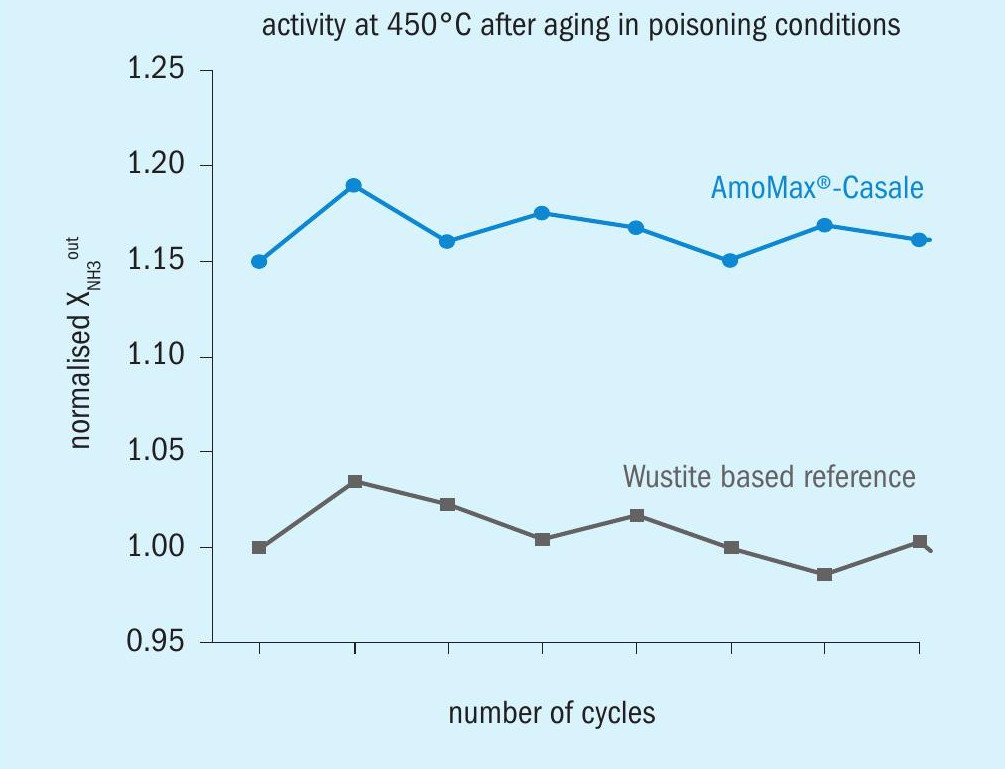
Stability
AmoMax-Casale shows an extraordinary stability in poisoning conditions. The performance was tested after each poisoning treatment and the activity was measured over time at fixed testing conditions without oxygen poisoning and after a stabilisation period.
As shown in Fig. 4 AmoMax® -Casale has proven to be very stable compared to wustite-based reference catalyst.
Mechanical tests
In addition, Casale and Clariant performed tests to assess the mechanical suitability of AmoMax® -Casale; in particular the main targets were to identify the intrinsic properties of the catalyst and how the catalyst would behave inside the Casale internals.
The tests performed to mechanically qualify the AmoMax® -Casale were:
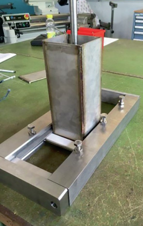
- Crushing strength properties in Casale internals: AmoMax® -Casale has been tested with an in-house tool (the so-called “Casale wall tester”, see Fig. 5) to assess the amount of powder produced due to friction of the catalyst with the Casale collectors. The AmoMax® -Casale crushing tendency has been compared with standard wustite and magnetite catalyst and no significant differences were found.
- Pressure drop: a test unit was set up to assess the pressure drop generated by the new catalyst and compared with standard catalysts used as references with the aim to evaluate the pressure drop result inside an axial-radial bed. The results obtained were in line with expectations and with the industrial pressure drop achievable in an industrial converter with a converter based on standard catalyst.
- Shear stress test: basically, this test is designed to apply stress to a test sample so that it experiences a sliding failure along a plane that is parallel to the forces applied. Therefore, this test is important in order to assess the effect of the catalyst on the Casale internals; after several tests the parallel stresses created on the internal surface are comparable to the ones measured with standard catalyst.
Casale internals design philosophy
Depending on the project type (new converter or revamping of an existing reactor), Casale can approach the ammonia synthesis converter in different ways.
In general, for a new pressure vessel the main goals are:
- full exploitation of catalyst;
- high reliability;
- highest catalyst volume filling efficiency to reduce the final pressure vessel sizes;
- easy access to internal baskets for maintenance or catalyst replacement.
For revamping, considering the possible physical constraints of the existing pressure vessel, the target is to provide the most efficient thermodynamic configuration combined with the maximum catalyst volume filling efficiency; reliability is another important target, while access to the internal baskets is determined by the existing pressure vessel configuration.
For a new converter Casale usually adopts the well-known configuration based on three catalytic beds with interchangers between the first and second bed and between the second and third bed, coupled with the use of Casale patented axial-radial internals.
In case of revamping the most frequent configuration is three catalytic beds with one or two interchangers; retrofitting an existing converter with Casale internals often means increasing the installed catalytic volume compared to the previous design.
The installation of a bottom exchanger is also quite common especially for revamps or the installation of a new pressure vessel in an existing synthesis loop.
In general, the higher efficiency of Casale internals together with the well-known Casale cold-wall design allows the converter to operate at a lower thermal level, thus improving its expected lifetime. Independent control of each of the three beds temperatures is foreseen since it is essential to obtain optimum operation of the converter at all times, i.e. with new as well as aged catalyst and at different plant loads, for maximum energy saving and thus highest return on the converter retrofit investment.
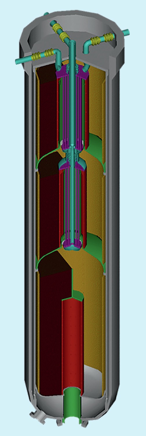
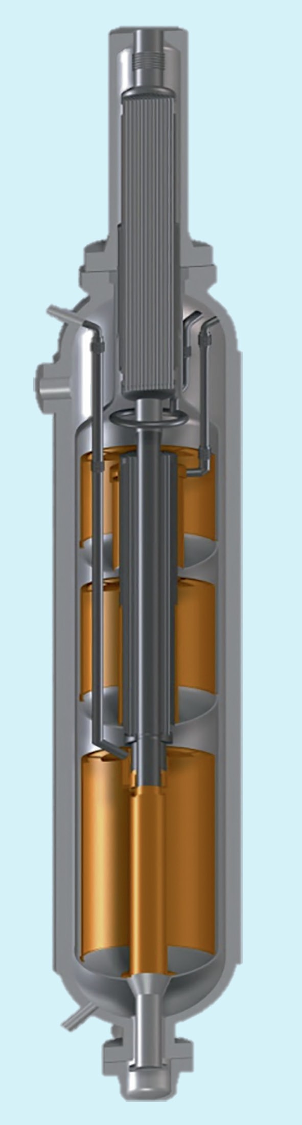
The new converter internal features are:
- a fixed cylindrical cartridge, which separates the catalyst baskets from the pressure vessel wall, allowing the vessel wall to be kept cool by flushing it with the incoming gas;
- first and second axial-radial flow type removable catalyst baskets for a three-bed design;
- a third (bottom) fixed axial-radial catalyst basket;
- two internal heat exchangers.
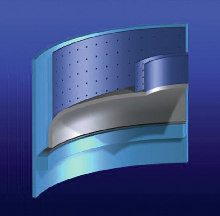
The catalyst beds have two cylindrical walls, one external (near the cartridge wall) and one internal, to contain and support the catalyst mass providing mechanical strength and to provide uniform gas distribution throughout the whole bed volume in order to get the best catalyst performance.
Each of the three axial-radial baskets is designed with an open top catalyst bed, which has the following advantages compared to conventional radial designs:
- utilises efficiently the full volume of the catalytic beds, including the top layer;
- easier mechanical construction, not requiring completely top sealed catalytic beds;
- easier catalyst loading and unloading;
- easy and controllable dense loading of the catalyst to obtain high and uniform bulk density.
To avoid any movement or spillage of the catalyst loaded in the top portion of the catalytic bed in upset conditions, suitable provision, such as slotted protection screens, are installed.
The material selection is performed to minimise or avoid high temperature Hydrogen attack and nitriding phenomena, that would affect the reliability and the life of the installed pressure vessel and internals as well.
The axial-radial flow pattern in the catalyst, results in an empty cylindrical core around the converter centreline, which is the ideal location for the interbed heat exchangers. To save costly converter space, Casale adopts a special design that allows high heat transfer rates to be obtained with comparatively low pressure drop and eliminates vibration problems. The bottoms of the removable baskets are inverted dished heads. Besides simplifying the sealing problems, this arrangement allows better utilisation of the converter volume (i.e. more catalyst can be packed in these baskets).
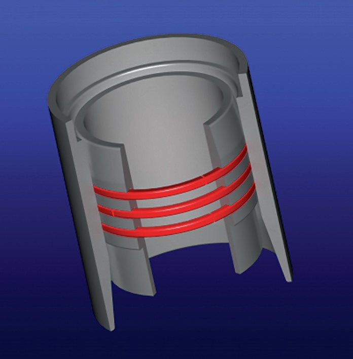
The different interconnected metal parts, which combined constitute the internals, reach very different steady state temperatures in an operating converter. To cope with different thermal expansions, Casale only uses bellows expansion joints where they are easily accessible for assembly and disassembly (i.e. at the reactor top). For converter inner parts, since they are not easily accessible, Casale patented elastic seal rings are used (Fig. 6). In this way it is possible to reduce internal leakages with smaller axial dimensions and shorter length.
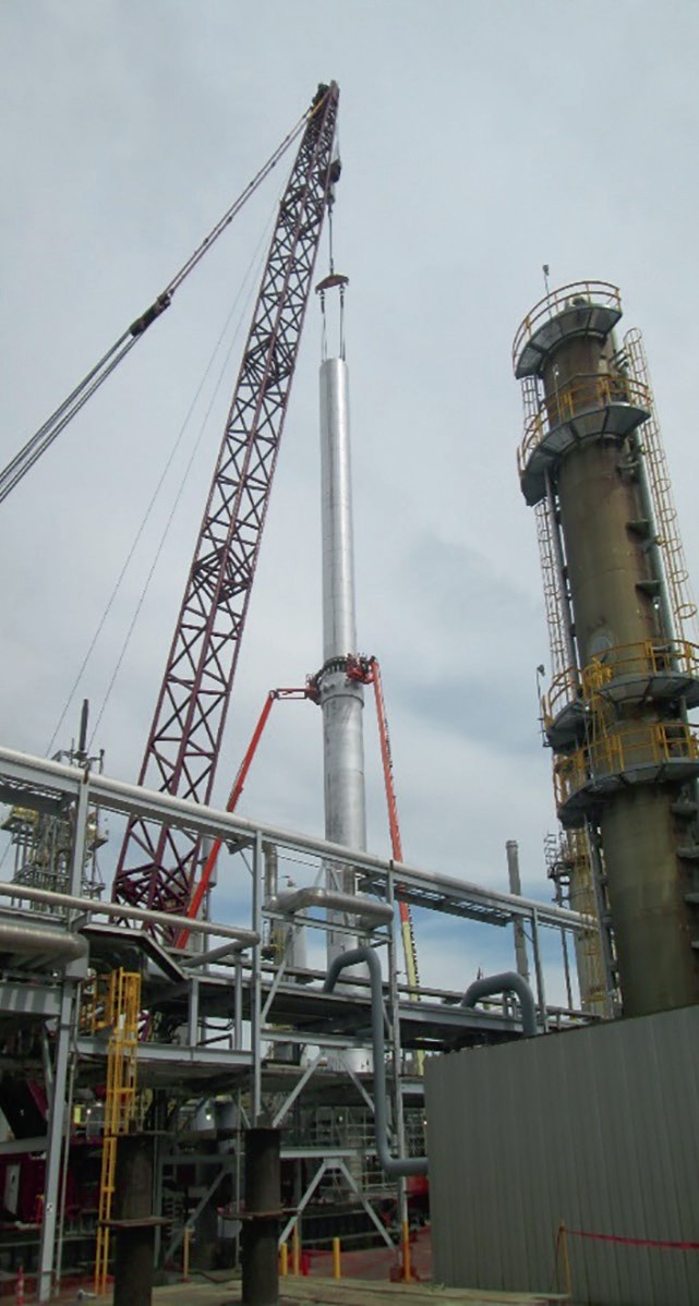
Casale internals installation
In case of converter pressure vessels with a fully open top configuration, this is unbolted to unload catalyst and remove the existing cartridge. The pressure vessel is then inspected, the stud bolts and gaskets seating surface are protected. A new cartridge is then lifted (Fig. 7) and installed inside the pressure vessel (Fig. 8). The expansion joint assembly on the converter outlet nozzle is installed and welded up to the cartridge bottom pipe, then the cartridge top cover is removed. After removal of the protection screen and lifting of the first bed basket, it is possible to unbolt and remove thermowell pipes.
To ensure a proper reading during converter operation, water moisture and dirt must be prevented from infiltrating the inside of the thermowell pipes: special care is therefore taken to plug and seal the thermowell pipes openings. Internal heat exchangers are already welded and in position inside the new cartridge; they are never normally removed during cartridge installation. Using the same procedure as for the first bed, the second bed basket is removed, and catalyst loading is started in the third bed.
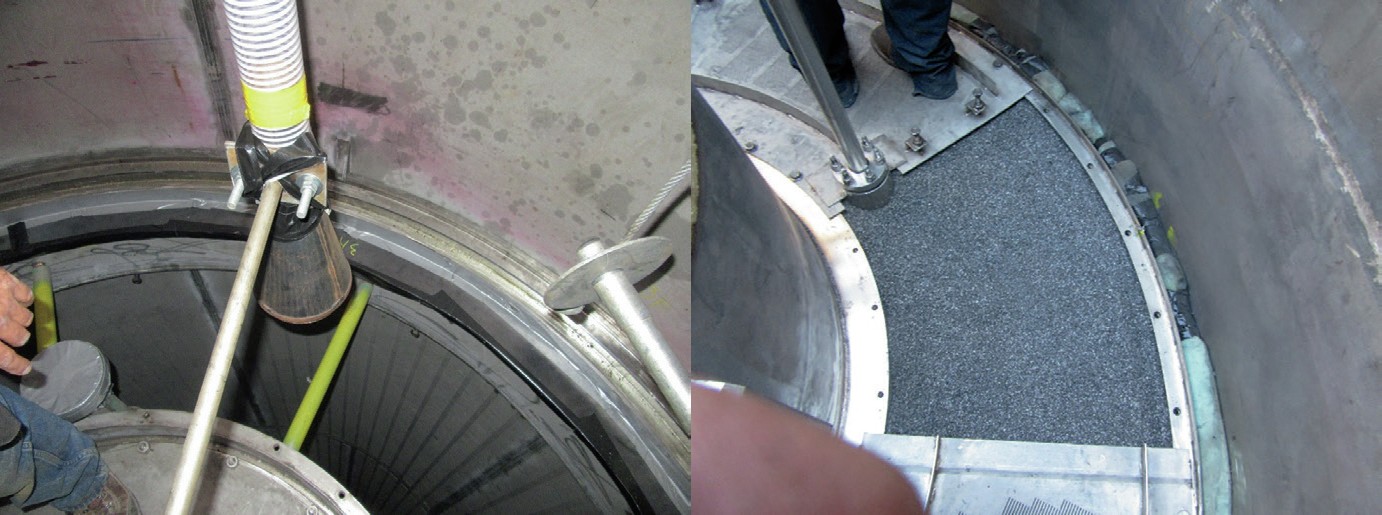
Special attention must be given during catalyst loading to preserve catalyst activity and the integrity of the converter internals. Oxidised catalyst is completely unreduced and does not present any risk of reactions with ambient air; conversely, pre-reduced and stabilised (RS) catalyst is obtained by the complete reduction of oxidised catalyst followed by skin oxidation for safe handling and storage. Reduced and stabilised catalyst can react with air even at ambient temperature; if such a reaction occurs, the temperature can easily rise since the oxidation reaction is exothermic, causing both catalyst and converter internals damage. For these reasons, pre-reduced catalyst loading (converter first bed) must be performed under a nitrogen atmosphere. Special nitrogen connections are used to flush the converter and a temporary cartridge closure cover and polyethylene sheet are used to cover all areas were catalyst is handled.
Catalyst is always screened before loading: in fact, it is sieved to remove any dust before loading in the drums and shipment, however some dust can form during handling and transportation.
Catalyst loading is performed by using a dense loader (Fig. 9). The amount of catalyst loaded is recorded while regularly monitoring (every 1,250 mm) catalyst distribution and bulk density (loaded catalyst weight and height are required) to maximise loaded catalyst bulk density.
After the third bed catalyst loading is completed, a relevant top protection screen is re-installed together with second bed and gaskets. Catalyst loading on the second and first bed proceeds as described for the third bed. Thermowell pipes and relevant stuffing boxes are also re-installed. During first bed loading, the bed temperature is carefully monitored to ensure that no oxidation is occurring.
The cartridge cover is then re-installed and insulation sleeves welded in the main inlet nozzle and start-up/bypass nozzle. Finally, central pipe assembly and expansion joints assemblies are installed, and the pressure vessel is boxed up.
All welds are 100% checked by dye penetrant test to ensure maximum reliability of internals. Installation of the new converter internals are accomplished smoothly in less than 15 days for a new converter, with no impact on plant scheduled shutdown time.
AmoMax® -casale operation in casale converters
As discussed previously AmoMax® -Casale catalyst provides up to 30% higher activity compared with the standard wustite based catalyst available on the market (reference catalyst). The combination and synergy of this catalyst with the best ammonia converter technology provided by Casale offers an unmatchable design with the highest possible attainable performances, in terms of lower synloop operating pressure and higher ammonia conversion.
These benefits can be easily converted into energy savings, lower natural gas specific consumption or higher production if the limitation to a plant load increase is provided by the synthesis loop.
In case of a new converter, AmoMax® -Casale can be used in all designed beds boosting the performances and the expected life, a different layout could foresee a first bed based on standard catalyst (this bed is working with fresh and unreacted gas).
A new converter based on AmoMax® -Casale catalyst and Casale internals to be installed in a new syntheis loop would have a smaller pressure vessel or a lower synloop circulation and therefore smaller equipment sizes with reduction of the relevant capex.
For ammonia synthesis converter revamping, as AmoMax® -Casale is more efficient than the standard reference catalyst, its logical application is in the last bed of an existing converter. Often the application of AmoMax® -Casale is also offered starting from the second bed of an ammonia synthesis converter. The application of AmoMax® -Casale in the first bed is not normally required for ammonia synthesis converter revamping as this basket is working with a very fresh gas (low ammonia concentration) and therefore the differences with a standard catalyst are not so significant.
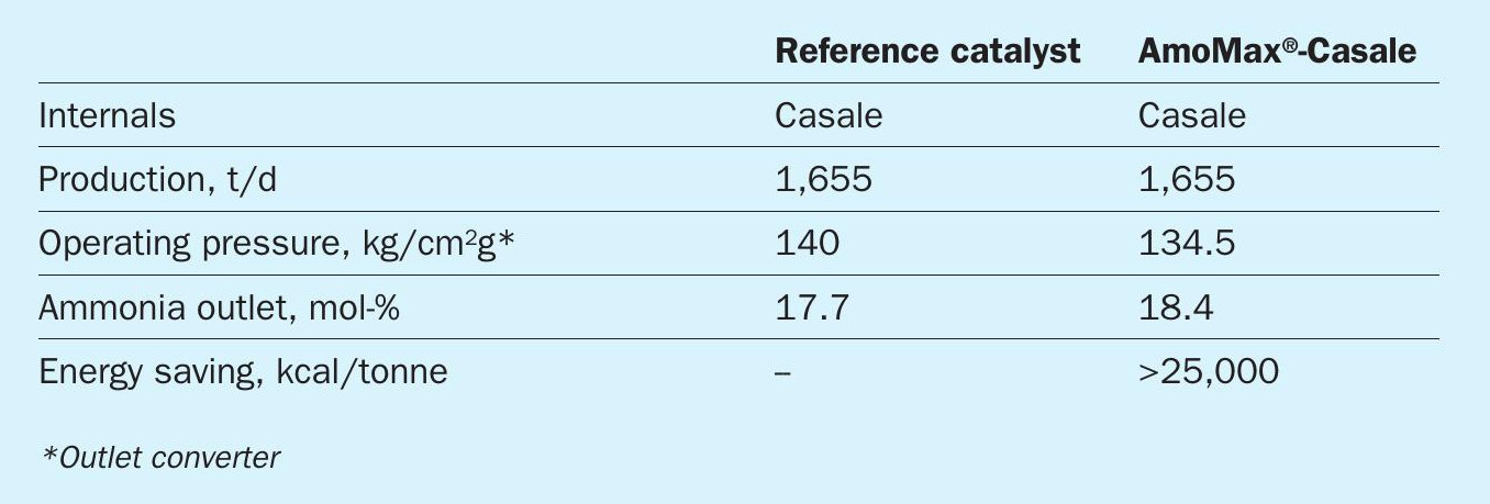
Table 1 compares the performances of a new ammonia synthesis converter pressure vessel designed with Casale internals and operated with standard wustite based catalyst available on the market (reference catalyst) or AmoMax® -Casale catalyst, based on the following boundary conditions:
- same catalyst life:
- same Casale internals;
- same new pressure vessel;
- AmoMax® -Casale loaded in the second and third catalytic beds.
Therefore, with an optimised ammonia converter internals configuration and based on the latest Casale technological improvements the AmoMax® -Casale catalyst is able to provide an enhancement of the overall synloop performance.
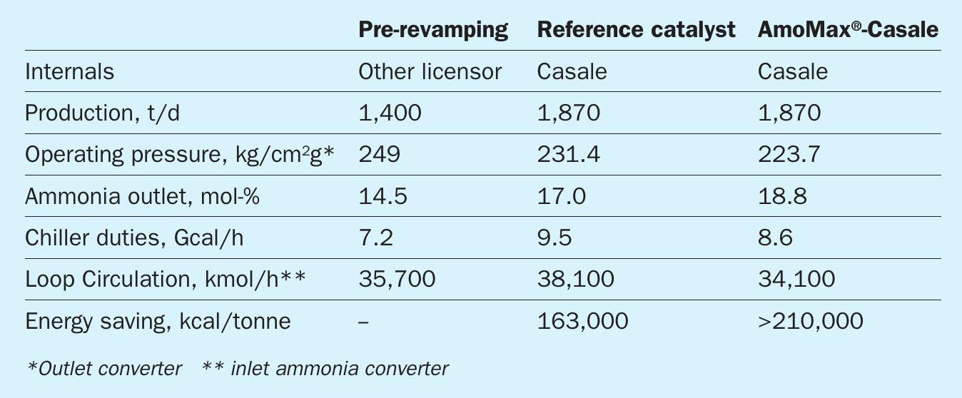
The installation of this new catalyst in a revamped converter (Fig. 10) can be even more effective considering that very often, an existing converter is working in conditions far from the original ones, and therefore with a design and configuration that may no longer be optimised for the current operation.
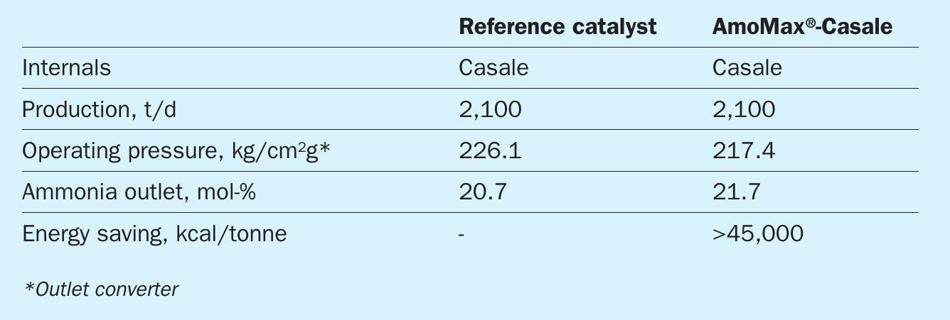
Consider, for example, two different design configurations, a GIAP bottle shape and a TEC bottle shape, based on the following:
- same catalyst life:
- Casale or competitor internals;
- existing pressure vessel;
- AmoMax® -Casale loaded in the second and third catalytic beds.
The benefits of AmoMax® -Casale in the revamped converters are presented in Tables 2 and 3.
The performances improvements in terms of energy savings and capacity increase are quite remarkable especially if compared with ammonia synthesis converter design different to Casale.
Conclusions
In a joint multidisciplinary effort involving process engineers, scientists, modelling engineers, and fluid dynamic engineers, Casale and Clariant have created a new ammonia synthesis catalyst and made it ready for the market in less than three years.
AmoMax® -Casale provides the following benefits to ammonia plants:
l Casale engineering adapted and optimised to use the newly developed catalyst;
l new catalyst efficiency index up to 30% more than wustite-based reference;
l higher tolerance towards poisoning and aging compared to wustite-based reference;
l Energy savings, lower natural gas specific consumption or higher production if the limitation to a plant load increase is provided by the synthesis loop.
AmoMax® -Casale has been successfully installed and started up in the first large scale ammonia plant in the Americas.