Nitrogen+Syngas 364 Mar-Apr 2020
31 March 2020
Finding solutions to problems in urea equipment
UREA EQUIPMENT
Finding solutions to problems in urea equipment
Schoeller-Bleckmann Nitec (SBN), an experienced manufacturer of high pressure equipment for ammonia and urea plants for many years, also helps customers when things go wrong. SBN has come to the aid of operators on numerous occasions, helping them return their plant to operation as soon as possible when a problem occurs. R. Bunzl discusses SBN’s approach to finding solutions to a number of exceptional problems in urea equipment.
SBN, part of the Christof Group, is a manufacturer of high pressure equipment for ammonia and urea plants. Over the past 20 years, SBN has manufactured more than 200 heat exchangers and reactors for high pressure urea synthesis. SBN is based in Ternitz, Austria, where there is a very experienced team in the workshop, mechanical and design engineers, welding engineers and non-destructive testing specialists, all contributing to the decades of experience and success of SBN.
Having manufactured so many vessels for urea plants, with many still in constant operation, SBN also gets involved when there are incidents during operation of these vessels. If, for whatever reason, a problem occurs, SBN is often called upon by the operators for immediate help in order to return the plant to operation as soon as possible.
This article describes several exceptional problems for which SBN has been approached to help.
Repair of a Pool Condenser tubesheet
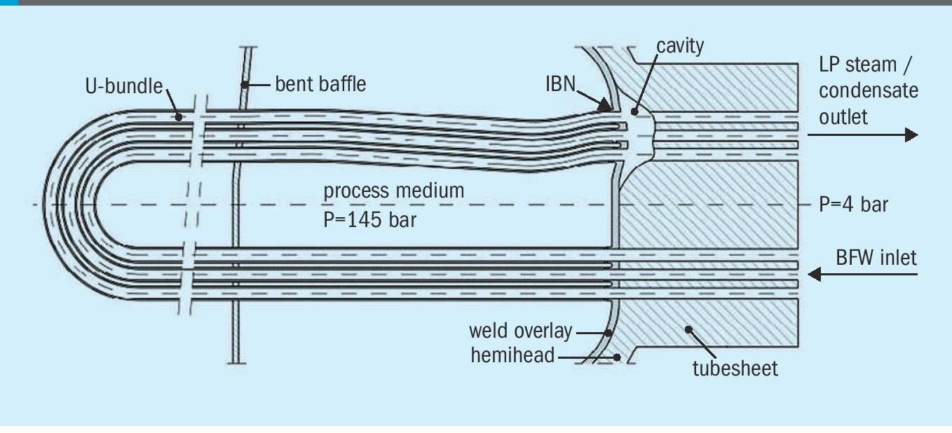
The Pool Condenser is a horizontal shelland-tube heat exchanger in the high pressure synthesis section of a urea plant. On the shell side, ammonia and carbon dioxide react to form carbamate and urea. The reaction heat is removed by passing steam condensate through the U-bundle.
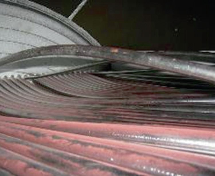
In this Pool Condenser the carbon steel tubesheet was severely affected due to flow accelerated corrosion (FAC), which created a large cavity. The cavity grew over a period of months and remained undetected until finally a sudden increase in conductivity triggered an alarm indicating a leakage. The plant was shut down and the Pool Condenser opened for inspection.
With the help of a video endoscope the inside of the tubesheet was inspected and the cavity was found. A severely deformed and buckled tube bundle was also discovered (Fig. 1). Fig. 2 shows a schematic of the cavity in the tubesheet.
The vessel damage meant the plant could not continue operating, so SBN was contacted by the client for a repair solution that would enable the plant to return to operation as soon as possible.
After a detailed study of different repair solutions, and taking into consideration technical and commercial aspects, it was decided to do a temporary repair of the damaged tubesheet and in parallel manufacture a new Pool Condenser.
The idea was to keep the tube bundle and weld overlay of the tubesheet, although deformed and sufficiently damaged that a leak occurred, but to repair the tubesheet as its mechanical integrity was the biggest concern. Since the damaged weld overlay was beyond repair, it was clear from the beginning that any repair could only be temporary and, due to the deformation of the overlay, additional leaks could still occur after the repair.
The repair was therefore only to keep the plant in operation until the new Pool Condenser arrived on site.
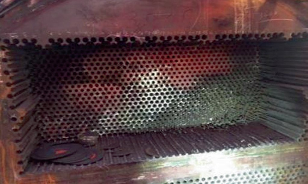
The repair method entailed completely removing the carbon steel of the tubesheet from the opposite side of the bundle in the area of the damage, but leaving the overlay untouched.The overlay could then be inspected and the amount of damage and cracks finally assessed.
Fig. 3 shows the CS part of the tubesheet removed to allow inspection of the weld overlay.
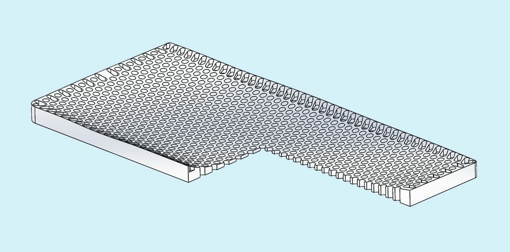
As expected, the overlay was severely deformed. It was clear that the three-dimensional shape of the deformation had to be recorded and a support plate with exactly the negative shape of the deformation needed to be installed. This support plate would avoid additional deformation after start-up of the vessel due to the pressure on the overlay from shell side.
To make this possible a 3D-laser scan of the deformed overlay was performed. The data were then used to exactly machine the same contour.
Fig. 4 shows the support plate for the deformed weld overlay.
After supporting the existing weld overlay the mechanical integrity of the tubsheet needed to be restored.
The solution was to close the cut-out in multilayer design. Since the tubesheet was bending due to the higher pressure on the shell side, the shear forces between the layers needed to be addressed. This was done with the help of high strength duplex sleeves, which also protected the carbon steel.
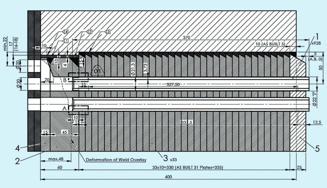
Fig. 5 shows a drawing of the repair. The repair was completed within the estimated and contractually agreed time of four months.
The repaired Pool Condenser was in operation for more than one year without any problems or unplanned shutdowns.
Re-design of a gasket seat
In the past, double cone gaskets were used by some companies as a standard gasket solution for manway covers in high pressure urea vessels. Some of these vessels are still in operation today.
Double cone gaskets need to be pre-tensioned to have contact on the conical face with the vessel wall. Additionally, thin layers of aluminium foils are used to improve initial sealing. Upon application of pressure it expands and is pressed further against the vessel wall to seal it.
A client of SBN operates a urea reactor, designed in the 1980s, with a double cone gasket. The client experienced leakages every few years, especially after longer plant shutdowns (without opening the vessel). Although the gasket is replaced every time, the leakage still occurs frequently.
It is assumed that these leakages occured due to slight corrosion effects and imperfect gasket surface geometry. SBN was asked what could be done to avoid these leakages and associated unplanned shutdowns.
SBN’s recommendation was to change the gasket type to the standard gasket system commonly used today. This is a serrated gasket made of urea resistant steel covered by a PTFE envelope.
This gasket is well proven and reliable. Due to the PTFE envelope, which is pressed by the serrated steel against the flange face, the sealing system is unaffected by pressure variations in the vessel.
The first option was to manufacture a new cover with the necessary geometry and additionally machine the existing manhole on-site with a transportable device. Afterwards, a solid gasket ring could be welded into the manhole. Finally, all open carbon steel parts need to be covered again by overlay welding with a urea resistant steel like 25-22-2.
A second option was also possible, since the original vessel had a multilayer shell design. Here, the multilayer design is a big advantage. Since no post-weld heat treatment is necessary when welding forgings to a multilayer shell, the complete manhole can be manufactured in the SBN workshop together with a new cover. The original flange is cut at the connection to the multilayer and the new one is welded on. This also reduces shutdown time of the plant during the change of the gasket seat.
After welding, the seam needs to be checked. Normally such seams are Xrayed in a workshop. But on-site, due to the restriction of all radiography, this becomes virtually possible. In such cases ultrasonic testing like UT-TOFD and phased array can be used. This is also covered by all major pressure vessel codes like EN 13445, AD-2000 or ASME. SBN has the equipment and experience to use this NDT technique on site.
Re-lining of a HP scrubber
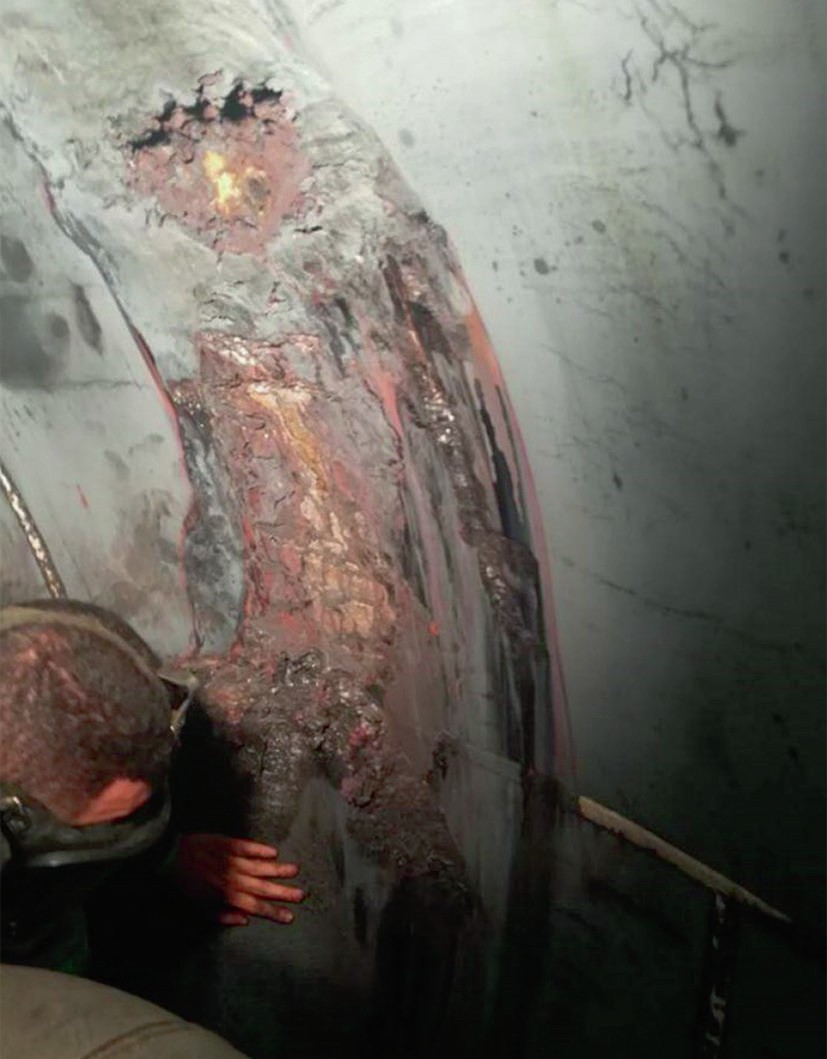
During a shutdown and inspection of the HP equipment a client of SBN recognised severe cracks over several square metres of the lining in a scrubber. It was clear that it needed to be replaced before it could go back into operation. After removal of the lining in the affected zone it could also be seen that even the carbon steel behind was already severely damaged.
Fig. 7 shows damage in a HP scrubber sphere behind the lining.
The damaged area was located in the sphere. The manufacture of spherical lining is much more complicated than lining for a cylindrical shell. This is the reason why many vessel manufacturers only do overlay welding in spherical formed sections of their vessels, and not lining.
SBN has extensive experience in manufacturing spherical vessels for urea plants with lining. The re-lining of existing vessels has also been performed many times.
For manufacturing a spherical lining the plates need to be first cut to size and then pre-formed on a press.
Fig. 8 shows the forming of a spherical lining segment on a press.
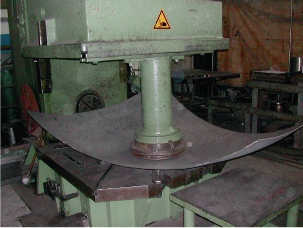
Forming requires a lot of experience and very skilful press operators to shape the segments. The segments need to be placed in the vessel several times during the forming process to check the shape. Only when the shape fits almost perfectly with the vessel can the lining be installed. Otherwise the gap between the lining and the carbon steel after welding the lining to the vessel may be too big. In this case the lining could crack when pressure is applied to the vessel.
In case of manufacturing re-lining material for an existing vessel there is of course no possibility to check the shape with the help of the real vessel. Therefore, a wooden model with the same shape as the existing vessel is built which can be used during forming.
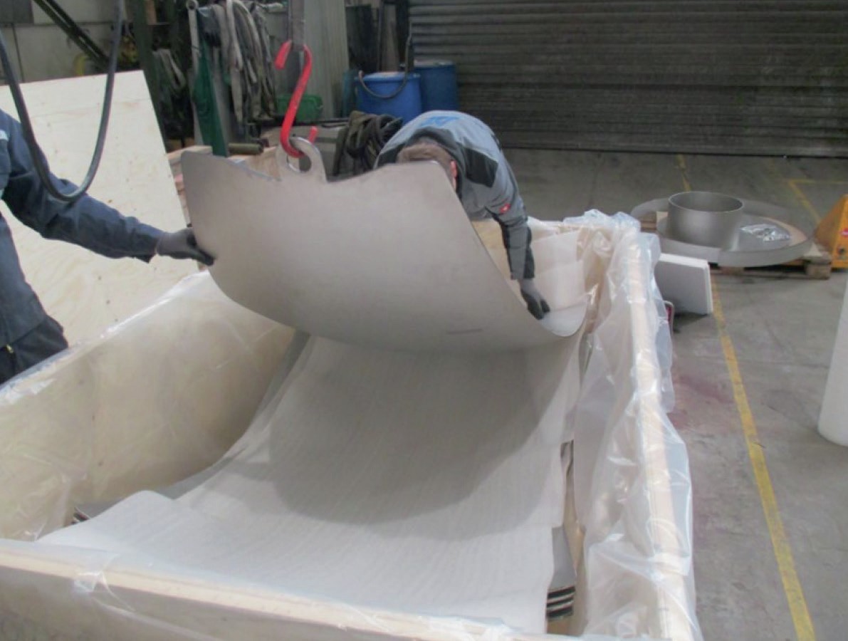
Since in such cases the shutdown times of the plant during the repair are one of the biggest concerns of the plant operators, SBN delivers the re-lining material in the quickest possible way. SBN has material of different urea resistant steel grades in different thicknesses in stock for such emergencies.
Fig. 9 shows packing of lining material for air transport.
Change of steel structure
SBN manufactures several replacement vessels a year for the high pressure urea synthesis section. Sometimes clients need just a replacement in kind with identical vessel dimensions and design. But for good reasons such a replacement is always an opportunity to increase plant capacity.
For the replacement of a HP stripper a client wanted to increase the capacity as much as possible. The heat exchanger part of the stripper, with its effective tube surface area, defines the capacity of the vessel. After re-calculations by a licensor it was decided to increase the number of tubes in the stripper. When SBN did the mechanical design of the vessel the client was informed about the new dimensions necessary to house the increased number of tubes. The client wasn’t aware of the increased size and weight and wasn’t prepared to change the steel structure where the stripper needed to be placed.
To do so SBN built the steel structure based on old as-built documentation in a CAD program.
Fig. 10 shows a 3D CAD model of the steel structure to accommodate the HP stripper.
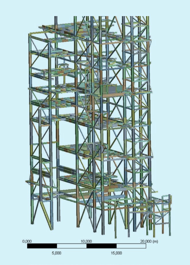
This model was used to perform different kinds of finite element analysis (FEA). First of all certain beams needed to be removed or replaced to increase the space necessary for the bigger vessel. Additionally the weight of the new stripper was increased and therefore especially the beams close to the stripper supports needed to be checked for their stresses and deformation.
Fig. 11 shows the FEA calculation result of local beams in the steel structure to support the HP stripper.
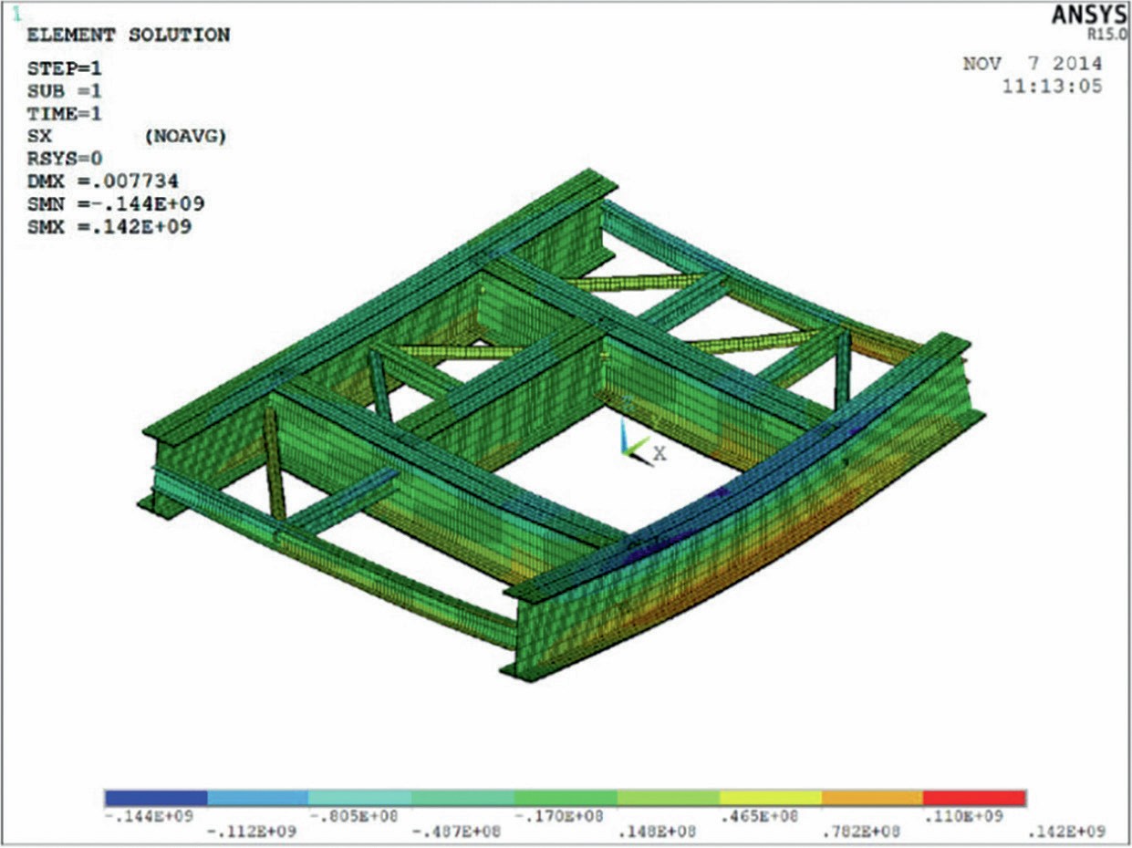
The complete structure also needed to be checked in terms of stability to avoid buckling. Especially during removal and installation of the stripper some beams needed to be removed to go in and out. This is the most dangerous load case and if not properly checked, there was the risk that the complete structure could collapse.
Fig. 12 shows an opening in the steel structure allowing entry into and out of the HP stripper with the help of a mobile crane.
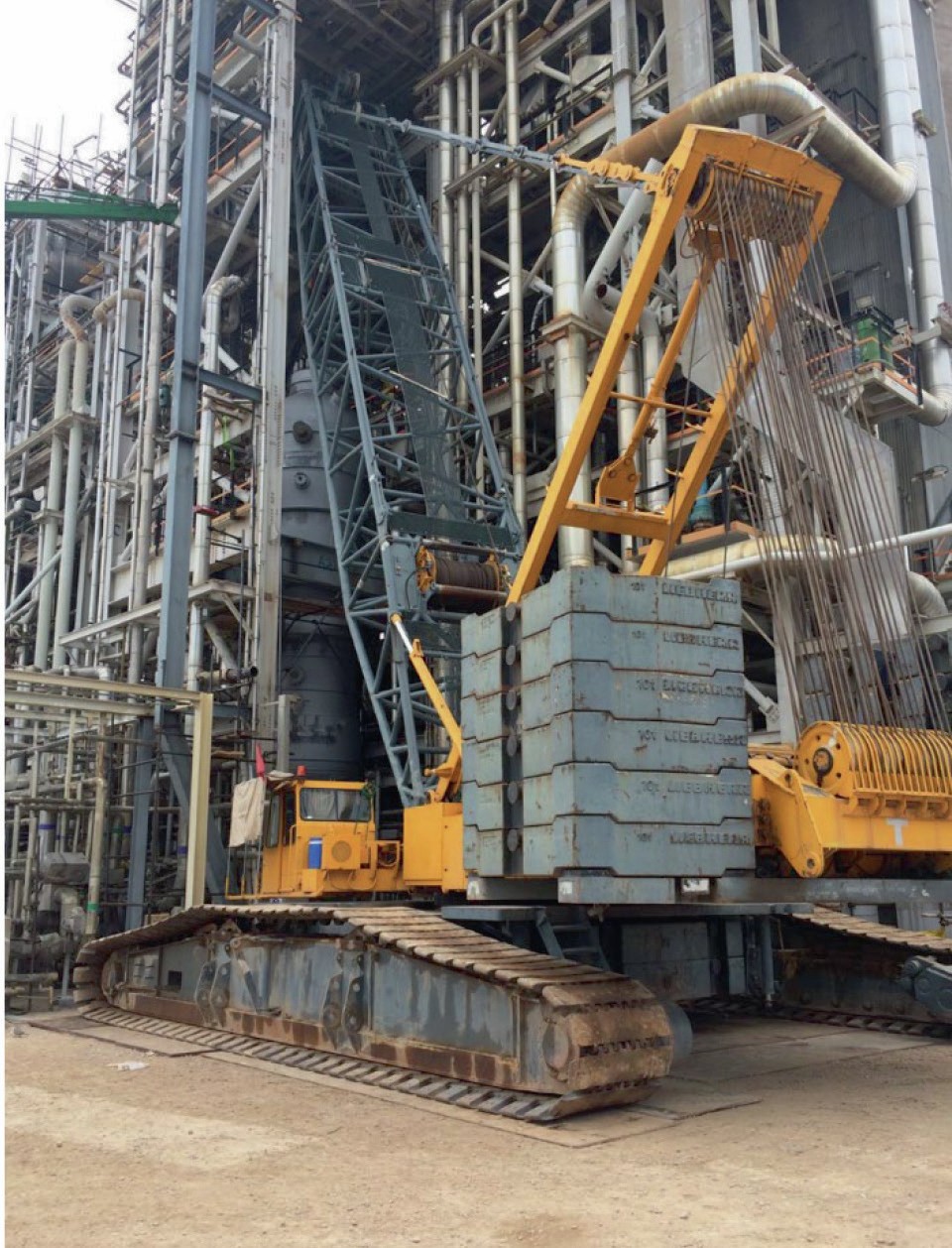
With these calculations SBN was able to support the client. SBN also prepared drawings for the necessary changes in the steel structure. The material itself and the erection work on the steel structure was organised by the client.
The stripper was finally installed without any problems.
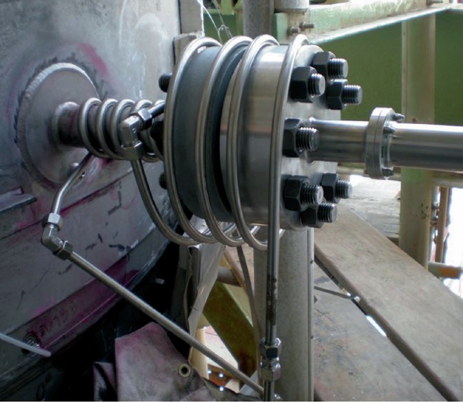
Change of level measurement system
In different locations in the high pressure urea synthesis section it is necessary to control the level of liquid for efficient operation of the plant. Due to the high pressure and temperature as well as the aggressive medium, level measurement is no easy task in these vessels.
Traditionally this has been done by using a radioactive source and a detector. For health and safety reasons this is very problematic and a radar level measurement system is now available on the market.
Unfortunately for existing vessels this radar measurement cannot be just placed onto the old nozzles for the radioactive source, a new nozzle is necessary.
Fig. 13 shows level measurement by radar in the bottom of a HP urea stripper.
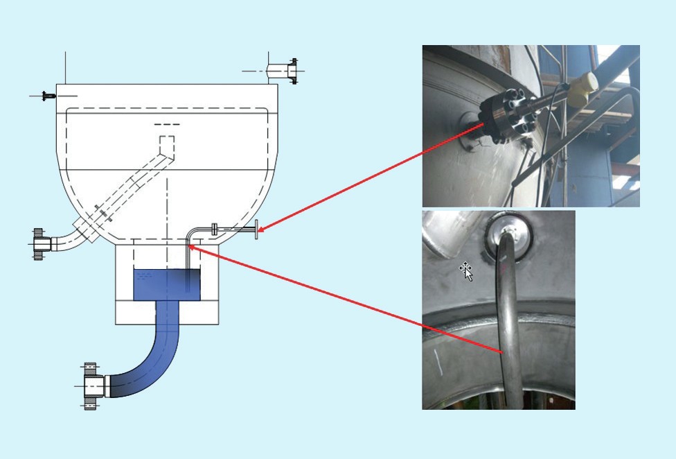
SBN can install new nozzles on site by drilling a hole into the vessel wall (Fig. 14) and welding in the new nozzle. The fact that these vessels are lined makes the task more complicated.
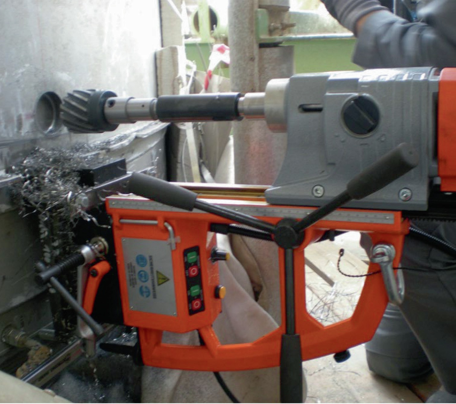
After drilling and welding in the new nozzle the corrosion protective lining and weld overlay needs to be closed again to avoid leakage and damage.
Fig. 15 shows a view from inside the vessel of an installed radar stand pipe. In addition to the machining and welding work, non-destructive testing is also necessary. This can also be performed by SBN.
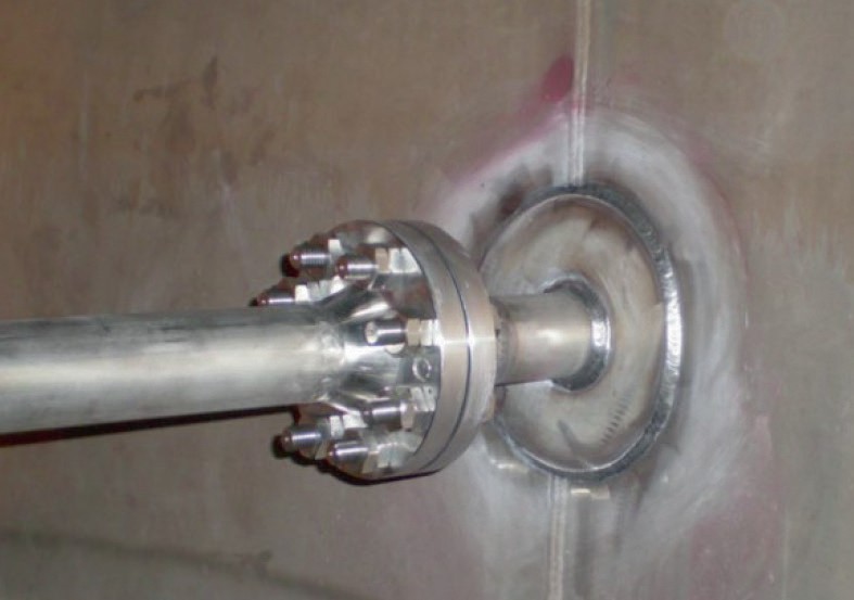
The radar measurement nozzles need to be heat traced to avoid problems later on due to cold spots and related corrosion problems.
SBN has successfully completed on-site radar nozzle installations several times. Typically only 1-2 weeks of shutdown time are needed to install the nozzle. Fig. 16 shows an installed radar nozzle from the outside with heat tracing.