Nitrogen+Syngas 364 Mar-Apr 2020
31 March 2020
Learning from successful plant commissioning
COMMISSIONING AND START-UP
Learning from successful plant commissioning
Lessons can be learned from the challenges faced during the construction, commissioning and start-up phases of major projects. In this article challenges and experiences are shared from the recent successful commissioning of ammonia and urea plants around the world, including projects in Indonesia, India, Egypt and the Middle East.

World’s first KBR Purifierplus™ ammonia plant in Indonesia
In 2018, PT Panca Amara Utama (PAU) successfully commissioned its 700,000 t/a ammonia plant located at Central Sulawesi, Indonesia. It is one of the biggest industrial projects in eastern Indonesia, supporting the government’s directive to increase domestic value addition and stimulate the local economy. The ammonia plant was specially designed to create a state-of-the-art facility with low natural gas consumption, high efficiency, and high reliability.
PAU ammonia plant is the first in the world to use KBR’s Purifier™ technology in combination with the KRES™ technology (namely KBR Purifierplus™ ) in one plant1 .
KRES™ technology has been successfully implemented in various existing plant revamps for capacity increase, energy reduction or natural gas saving, while Purifier™ technology has been successfully used in both grassroots plants around the world since 1966 as well as for existing plant revamps. PAU is the first grassroots plant used Purifierplus™ technology, which makes this plant unique.
Commissioning of the PAU ammonia plant was successfully completed in August, 2018 with one of the lowest energy and natural gas consumption figures per tonne of ammonia.
Challenges and lesson learned
Successful commissioning of an ammonia plant requires careful planning and utilisation of lessons learned from other successful start-ups. Below are some of the main challenges and lessons learned during the plant commissioning and start-up of the PAU plant.
Prevention of solution foaming in the CO2 removal system
Key to trouble-free, quick start-up and stable operation of the OASE white CO2 removal system is the effective prevention of the foaming of the OASE solution. Solution foaming can lead to significant operational upsets, and may cause damage to column internals, solution pumps, and heat exchangers in the system. It may also damage downstream equipment and catalyst due to solution being carried over to methanator. Hence, it is vitally important to ensure removal of the foaming causing agents, such as grease, oil, dust and fine particles from the system.
Following KBR advice, in the pre-commissioning phase, a very thorough cleaning and degreasing of the system was performed. The fact that degreased packings were procured also helped the cause. In the commissioning phase, two other important steps were carried out before process feed introduction to the system:
- Performance of a passivation step to form a magnetite layer (Fe3 O4 ) that protects the carbon steel surfaces from corrosion;
- LTS catalyst de-dusting to prevent fine particles from entering the system.
Continuous filtration of the recirculating OASE solution was maintained during startup and normal operation.
To prevent foaming, tests were carried out twice a shift on the recirculating OASE solution and adjustments were made accordingly to the anti-foam injection program which comprised continuous injection using the installed anti-foam injection pump skid and also e ach shift “shot” dosing using the installed “shot pots”.
Because of these measures, the PAU OASE White CO2 removal system has been running very smoothly and no foaming problems have been encountered since initial start-up.
CO2 ingression into the N2 plant
During start-up and soon after the ammonia plant was producing CO2 , the OSBL cryogenic nitrogen plant tripped several times due to icing caused by high CO2 content in the outlet stream of the molecular sieve dryers to the cryogenic section of the plant.
It was observed that, due to prevailing wind conditions, the CO2 vent from the ammonia OASE system was settling towards the air suction intake of the nitrogen plant compressor. CO2 mapping around the plant confirmed the phenomenon. During mapping, it was observed that the CO2 level in the area of the process air compressor was unaffected. As a solution, an additional air feed line for the nitrogen plant was taken from the process air compressor of the ammonia plant. CO2 mapping is carried out on a regular basis and air is sourced from the process air compressor if needed. As a result, the nitrogen plant had been running normally.
This problem could have been avoided if proper dispersion modelling had been carried out by the detailed engineering contractor before finalising the layout of the units in the plant.
Oil ingression into the dry gas seal of refrigerant compressor
During commissioning of the refrigerant compressor, lube oil leaked into the dry gas seal of the compressor due to failure of the nitrogen supply (separation gas) to the bearing housing. Spare dry gas seals were installed and the plant was re-started. Nitrogen backup with a battery of nitrogen cylinders was subsequently provided.
Delay in completing cleaning of the lube oil systems
Cleaning of the lube oil system for the major compressors, process air compressor, refrigerant compressor, and syngas compressor was prolonged and led to a delay in the plant commissioning. Cleaning of the air compressor lube oil took nearly nine months, as did the cleaning of the lube oil of the syngas and refrigerant compressors, which shared a common oil system.
The problem could have been avoided if proper pickling and air blowing of the lube oil piping was done before starting the flushing activity.
Erratic readings from steam flow transmitters
After completion of the nitrogen circulation heating and starting initial steam introduction to the primary reformer and KRES, it was found that all of the steam flow transmitters were showing different readings. It was observed that the impulse line tapping of the flow transmitters had not been installed as per KBR standard. The problem was resolved after the layout of the impulse line was modified from a 45° angle to horizontal as per KBR recommendations.
Delay of air blowing due to damage to auxilliary boiler
Two auxiliary boilers were provided to meet the ammonia plant start-up and commissioning steam requirement. However, during commissioning, tube leakage was observed in one boiler, causing a delay to the commissioning of the process air compressor, which in turn delayed other commissioning activities like air blowing of the plant pipelines.
Underperformance of methanator effluent water cooler
During start-up, it was found that the methanator effluent water cooler was underperforming and the process outlet temperature was about 12-15°C above design. Upon investigation it was concluded that the problem was caused by a fabrication defect – part of the internal partition plate was missing and led to bypass of the synthesis gas. The underperformance of this exchanger led to increased load for the downstream chiller and on the refrigerant compressor.
Repairs were done by the manufacturer, which involved extending the partition plate. However, the problem has not been fully resolved as the hot gas outlet temperature is still (approximately 6-7°C) hotter than design.
Despite the problems encountered, the PAU ammonia plant successfully demonstrated that its performance was better than the guarantees and design in terms of energy consumption, ammonia production capacity and product quality.
KBR world’s lowest energy ammonia plant at CFCL, India
To meet the demand for urea in India, in January 2019, Chambal Fertilisers and Chemical Ltd (CFCL) successfully commissioned its third ammonia/urea plant (G3AU Project) with a capacity of 2,200 t/d ammonia and 4,000 t/d urea at its existing facilities at Gadepan (Kota, Rajasthan) in India2 . Since commissioning the new ammonia/urea plant, CFCL has now become India’s largest production capacity of urea at one location.
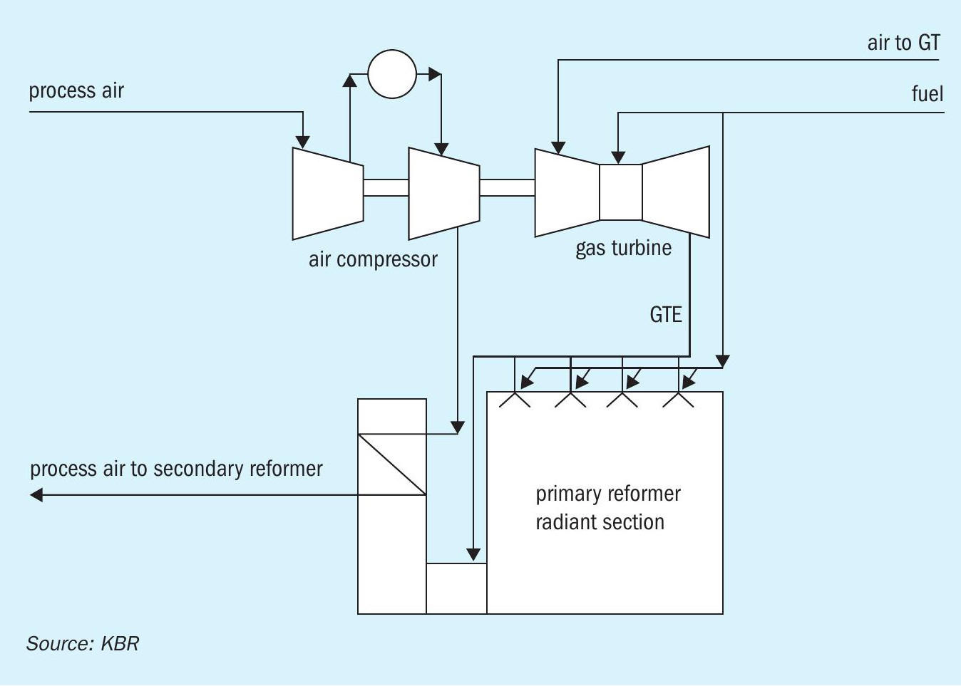
Due to the high cost of natural gas in India, CFCL wanted the new plant to have lowest possible energy consumption. CFCL also desired the plant to be self-sufficient in terms of MP steam. It was therefore decided that the process air compressor would be driven by a gas turbine and the hot gas turbine exhaust would be used as preheated combustion air for the primary reformer (Fig. 1). This configuration improves the thermal efficiency of the gas turbine from around 30% to over 95%, allows more steam export to the urea plant for its turbine-driven CO2 compressor and also eliminates the requirement of the forced draft fan and combustion air preheater. Due to its unique features, the ammonia plant has become the world’s lowest energy plant using KBR’s Purifier™ ammonia technology.
Project execution
The lump sum contracts for engineering, procurement and construction (EPC) for the development of the entire facility i.e. ammonia/urea/OSBL were awarded to TOYO. TOYO in turn awarded contracts for the ammonia plant license, basic engineering design packages, and supply of licensor’s proprietary equipment to KBR.
To ensure safety, quality and consistency of the overall plant design, KBR also supported TOYO/CFCL in the activities, such as review of the critical documents, critical equipment inspections, participation in Hazop, 3D model reviews, supervision during catalyst loading of the reformer, ammonia converter etc.
KBR also provided pre-commissioning, commissioning and start-up advisory services with 24×7 coverage for safe, fast and efficient start-up of the ammonia plant.
Throughout all phases of the project, CFCL, KBR and Toyo worked together for the common goal of design and construction of a safe, reliable and energy efficient world class ammonia plant.
Challenges and lesson learned
Several challenges were faced during the commissioning and start-up of the plant.
Purifier outlet valve stuck
A high pressure drop of 5 kg/cm2 was observed between the expander outlet pressure and syngas suction pressure during a start-up, after plant tripping. Upon checking, a high pressure drop was observed across purifier outlet valve, while the valve stem was in full open condition. This was creating a load limitation due to lower syngas compressor suction pressure.
During a short shutdown of the plant, the purifier outlet valve was replaced with a manual isolation valve. Upon checking the replaced valve it was found that the disc was disconnected from the stem and the valve was stuck at 40% open position, which was creating a high pressure drop.
Leakage from expander flange
The purifier was checked for any leakage at 30 kg/cm2 g with syngas before startup and no leakage was detected at that time. After commissioning the purifier, a minor hydrogen leak was observed from the sample point of the expander duct during routine checking of leaks in plant. The hydrogen concentration was in the range of approximately 4% and reduced to about 2% after increasing the nitrogen flow to the duct. The nitrogen hose was provided at the vent point to avoid an explosive mixture.
To reduce the leak from the flange in the expander compartment, the syngas compressor suction pressure was reduced by 1.0 kg/cm2 compared to design, which increased the load on the syngas turbine.
Expander bypass valve operation
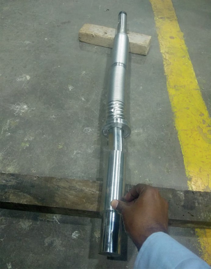
During stroke checking of the expander bypass valve, it was observed that valve operation was not smooth. The vendor checked and found that due to the actuator weight, the valve stem had bent (Fig. 2). During installation of the valve, the support for the valve actuator was not installed properly which led to the bending of the valve stem. The valve stem was replaced and valve operation returned to normal.
Oil Ingress to synthesis gas compressor dry gas seal
During start-up of the plant, after tripping, a small amount of lube oil was observed from the syngas compressor LP stage NDE side dry gas seal drain. A probable reason for the oil ingress was no backup of nitrogen from the existing nitrogen plant. Later on nitrogen backup was provided with a battery of nitrogen cylinders.
Heat leak from air compressor anti-surge valve
The ammonia plant tripped due to low air flow to the secondary reformer actuation. It was observed that initially the anti-surge valve opened which led to low process air flow to the secondary reformer and finally a full plant trip on the MP steam header fluctuation.
The root cause for the anti-surge valve malfunctioning was a heat leak from the control valve body. Proper insulation of the valve body was carried out to avoid the heat leak to instruments.
Cooling water high pressure drop
Lean cooler 108-C is a plate type heat exchanger which cools lean solution using cooling water as the cooling medium. During commissioning, it was observed that cooling water flow through the lean cooler was lower than design due to high pressure drop across the plates. The matter was discussed with the vendor and the problem was resolved by replacing the wrong type of plates with the correct type as well as installing 20% additional plates.
The CFCL plant was successfully commissioned and became the world’s lowest energy ammonia plant despite the problems listed above.
ENPC ammonia/urea project in Egypt
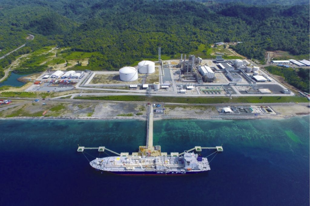
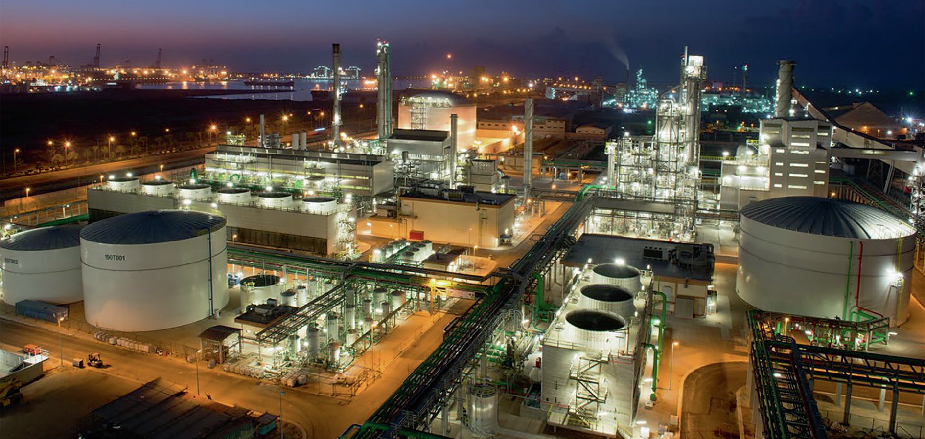
In 2016, the two train ammonia/urea fertilizer complex ENPC, owned by ENPC (Egyptian Nitrogen Products Company) was successfully commissioned3 . The complex is located in New Damietta (Egypt) near the Mediterranean Sea (see Fig. 3).
The ENPC complex consists of:
- 2 x 1,200 t/d ammonia plant (Uhde process with Johnson Matthey catalysts, UOP Benfield CO2 removal);
- 2 x 1,925 t/d urea plant (based on Stamicarbon synthesis and Stamicarbon granulation);
- all offsite and utility facilities, including 72,500 t urea storage.
In this project, thyssenkrupp Industrial Solutions (tkIS) was the EPC contractor, supplying its Uhde® technology and having the responsibility for engineering, procurement, construction and also for the commissioning and start-up of the entire complex.
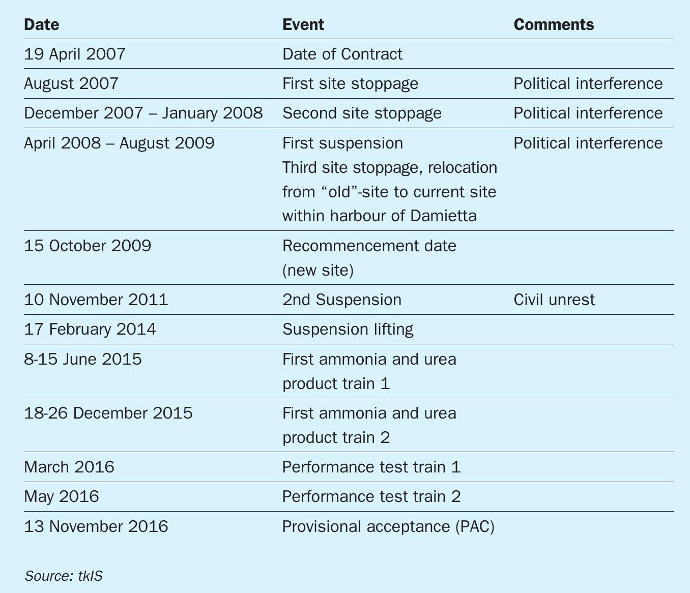
Project history
In total the ENPC project had a running time of 9½ years from date of contract signature until the achievement of provisional acceptance. Three stoppages and one site relocation in between were the main reason for the long project time.
The last stoppage fell in the phase of precommissioning of train 1 (see Table 1, “2nd suspension”).
Challenges during (pre-)commissioning
The main (pre-)commissioning challenge for the ENPC project was a 27-month project suspension due to political unrest.
The first (pre-)commissioning started in August 2011 and was interrupted shortly after by the suspension in November 2011, when all activities on site had to be stopped.
After resuming the project in February 2014, first with detailed inspections of the condition of the complex, construction resumed followed by first (pre-)commissioning activities in July 2014.
All previous (pre-)commissioning activities had to be repeated in addition to an intensive cleaning and repair effort for all affected sub-systems, which suffered during the suspension period.
Interruption of first (pre-)commissioning phase
In September 2011 the (pre-)commissioning started with air blowing of the interconnecting piping network between the battery limits and the two trains as well as for the fuel gas system. In parallel, pre-commiss ioning by water flushing for some utility systems was ongoing. The events mentioned here are discussed in more depth in reference 3.
In early November 2011 the site had to be left suddenly due to civil unrest in context with the “Arabian Spring” and unfinished sub-systems of train 1 had to be left in their current condition. For example:
- The cooling water system was filled with untreated town water for initial flushing.
- The boiler feed water system in the utilities and in the ammonia plant partly filled with demineralised water. Parts of the system were exposed to a seashore atmosphere due to dismantling of control valves for flushing activities.
- Fuel and feed gas system were exposed to a seashore atmosphere. Water from air humidity condensed inside the piping causing corrosion.
Preservation and conservation measures
The site was inaccessible for around six weeks, until mid December 2011. When the tkIS project team returned to site in December 2011, after an initial inspection of the conditions on site, no further site activities were possible until the civil unrest outside the complex ceased.
Preservation procedures were prepared based on the assumption of a stoppage of all further site activities for a few months. Due to the situation in the country, only a few activities could be done in order to minimise damage to train 1.
- Only a few equipment items could be filled with clean water with pH control or filled with nitrogen.
- Several sub-systems filled with water from the hydrostatic testing could not be emptied, e.g. ammonia refrigeration system train 1.
- The shafts of the major turbines and compressors were not turned at regular intervals as requested by the vendor (once per week)
Second (pre-)commissioning phase
After tkIS’ return to site in February 2014, inspection, preparation and first construction activities took place between March and July 2014. In July 2014 the (pre-)commissioning activities resumed with the interconnecting system between both trains and the plant and instrument air system of train 1.
The (pre-)commissioning and start-up phase for train 1 was a success without major safety incidents with all parties following the strict safety protocols.
Major rotating equipment like e.g. the synthesis gas compressor were specially inspected and repaired after the suspension involving the vendor specialists, as well as specialists from tkIS and ENPC.
During (pre-)commissioning of the first train the second train was still under construction, which allowed replacement of defects in train 1 by utilising the corresponding parts from the identical second train, if in usable condition.
The (pre-)commissioning activities for the gas-containing sub-systems in train 1 went smoothly. Major damage was mainly detected for control valves, flanges and gaskets, e.g. lens gaskets. Whenever possible the damaged parts were repaired, e.g. resurfacing of lens gaskets. Air blowing was repeated several times to remove all the accumulated dirt and rust in the system. The effort required for pipe cleaning was approximately two to three times higher than for projects without interruption.
For the water containing sub-systems the situation was different. Since several of the sub-systems were filled with water during the suspension and were partly exposed to the seashore atmosphere, a much higher amount of damage was found during the construction and (pre-)commissioning phase. In particular, carbon steel piping, e.g. in the cooling water system, was heavily affected. Several parts of the piping had to be replaced after intensive inspections. Besides the cooling water system, the ammonia refrigeration system also showed a high amount of corrosion.
Unfortunately, during the commissioning phase, while synthesis gas was introduced into the ammonia synthesis loop under pressure, a leakage in the gas cooler downstream of the gas/gas heat exchanger was detected. The gas cooler is a shell-and-tube heat exchanger in which the ammonia containing synthesis gas is cooled down with cooling water.
After the detection of the leakage the ammonia synthesis was immediately depressurised and purged with nitrogen over several days with continuous hazardous gas monitoring.
During the following inspection of the heat exchanger by endoscopy and eddy current several leakages in the tubes were detected, requiring urgent replacement of the complete gas cooler. The inquiry and purchasing of a replacement heat exchanger would have taken several months, jeopardising the complete project schedule. However, by lucky coincidence a replacement gas cooler with the same specification was found at another ammonia producer, and because of the good cooperation between companies it was quickly transferred to ENPC.
The replacement of the gas cooler was thus executed in a very short period of seven days, considering the difficulty of keeping a positive nitrogen pressure in the ammonia catalyst beds and cutting the attached piping to the heat exchanger. A detailed safety analysis including a safety area with limited access was implemented around the heat exchanger. During the replacement of the heat exchanger all safety rules were strictly followed and there were no safety incidents or near misses. In summary, it was a remarkable effort considering the time criticality and difficulty of the job.
For the ammonia refrigeration system (having been filled with water during the interruption period), the situation was quite different. During the (pre-)commissioning phase leakages in the sub-systems of the ammonia refrigeration were detected. On the contrary to the cooling water system, it was not possible to replace affected parts of the piping system one after another later during operation since the operating media is hazardous ammonia. Consequently, the affected sub-systems were carefully emptied, inspected and corroded parts exchanged. Since it was not possible to inspect the complete ammonia refrigeration system in detail due to its size and the fact that most of the system had already been covered by cold insulation foaming, a job safety analysis had been executed in which it was decided to implement a safety area around the ammonia refrigeration system (including affected systems like the ammonia synthesis loop) with only limited access. During the initial filling of the refrigeration system with ammonia and the start-up of the system the plant was evacuated and all points were observed over weeks to detect any possible leakages and defects in the piping. Except for the previously found leakages, no additional ones were found. The safety area around the refrigeration system was kept for a longer time period until the plant was in a steady and stable operation mode.
In addition to the damage found in the mechanical systems of the plant resulting from the suspension period, the stored catalyst material and packing material also showed significant signs of corrosion. In case of the primary reformer catalyst and the packing material of the CO2 removal unit, the material had to be spread out over a wide area and sorted manually.
Shortly before starting the reduction of the ammonia synthesis catalyst in train 1, several leakages occurred in the ammonia synthesis loop and at the synthesis gas compressor. In particular, damaged lens gasket surfaces of quench valves directly at the converter pressure shell caused several delays due to the complicated re-machining of the surfaces at elevated heights. Therefore, the ammonia synthesis loop had to be depressurised and purged over several days.
Case studies
The following case studies discuss three different challenges faced by thyssenkrupp Industrial Solutions and their successful solutions during the commissioning of ammonia and urea plants.
False readings from synthesis gas moisture analyser
This case study refers to an ammonia plant where a synthesis gas drying unit is installed between the stages of the synthesis gas compressor. In this drying unit the makeup synthesis gas is passed through molecular sieves in order to remove remaining water vapour before the gas enters the ammonia converter.
According to the operating procedure from the ammonia catalyst supplier, the water content of the gas entering the converter should be kept as low as possible to avoid catalyst deactivation. Typically, the desired value in this particular application is less than 1 ppmv moisture.
During the recent commissioning of an ammonia plant in the Middle East the synthesis drying unit was put online. At the same time, the moisture analyser reading downstream of the drying unit was swinging with an amplitude of up to 200 ppmv. This meant that there were severe concerns about feeding the synthesis gas into the ammonia converter. A calibration of the moisture analyser was done, but the periodically high reading remained unchanged.
On the fourth day of the synthesis drying unit being online a pattern in the moisture reading was noticed. A peak in moisture reading was observed daily at noon, which coincidently is the time with the highest ambient temperature.
An effect on the moisture reading due to high levels of sun radiation was expected. Sun shades were installed and the analyser box was continuously purged with plant air which acts as a coolant in the analyser box.
With this arrangement the moisture reading became stable and commissioning of the ammonia synthesis unit could continue without any fear of deactivating the catalyst.
It was later learned that this cyclic effect is defined by the so-called “diurnal effect” and is typical for analyser systems which are located in outdoor locations. This effect is a real moisture change in the process sample system, associated process piping and vessels.
The polar nature of the water molecule allows it to adsorb to all surfaces with a full or partial ionic charge, like iron oxides on the inside of process piping or equipment. The equilibrium of the adsorption depends on the temperature.
During nighttime, due to lower temperatures, water molecules are adsorbed onto the inner pipe wall in equilibrium. This adsorbed water leaves the pipe wall as it heats up during the day time and enters the gas system.
The moisture analyser reading was influenced by the swinging ambient temperature within the analyser box. As soon as the temperature in the analyser box was stabilised by plant air purging no more fluctuations were observed.
The lesson learned from this incident is that the moisture analyser reading can be influenced by environmental conditions and that an appropriate arrangement should be considered to avoid analyser box temperature fluctuation.
Adjustment of biuret content of urea product
Urea product contains biuret, typically up to 0.9-1.2 wt-%. As biuret is a plant poison and the marketability of granulated urea product is somewhat limited when containing higher amounts of biuret the intention is to reduce biuret to a minimum.
In 2013, thyssenkrupp Industrial Solutions (tkIS) commissioned a urea plant using the Stamicarbon LAUNCH MELT™ technology for synthesis and the UFT® Fluid Bed Granulation technology licensed by thyssenkrupp Fertilizer Technology (tkFT). While maintaining the other product qualities, a significantly lower than 1.0 wt-% biuret in the solid product seemed nearly impossible to achieve.
It is well known that biuret formation increases at high temperatures and concentration as well as residence time while the urea is liquid. These conditions are found in the recirculation and evaporation section. Consequently, the residence time can be reduced by minimising the liquid levels in the rectifying column outlet, the flash vessel, and in the urea solution tank. By doing so, the biuret content decreased but still remained above the required value. Beside the evaporation section, high temperatures also occur in the HP section of the synthesis. However, the high temperatures in the HP section are required in order to achieve sufficient reaction progress. Consequently, it was decided to focus on the evaporation section and reduce the temperature of the urea melt using different approaches. tkIS urea plants are equipped with level control at the evaporator shell side which allows partial submersion of the tubes with condensate. While parts of the tubes are submerged, the area of heat transfer is reduced leading to a reduction in the residence time of liquid urea in contact with the hot inner tube surface. The steam supply to the evaporators is equipped with pressure control valves, allowing the shell side temperature to be adjusted. Reducing the steam pressure also reduced the temperatures which the liquid urea is exposed to. By increasing the vacuum in both stages of the evaporation, the melt temperature in the outlet could be reduced by some 1-3 K. Further reduction of the temperature was not possible because the melt temperature came closer to the crystallisation point. Still there was the possibility to shift the load from the first to the second stage and the other way around in order to try and find the optimum for the biuret formation. Unfortunately, despite all optimisation performed in the evaporation section, the biuret content remains above the required value.
In order to search for the cause of the unexpected high biuret content the parties involved decided to increase the location of samples taken in the recirculation and evaporation section. The sample analysis did not show essential changes in biuret content in the urea melt and urea solution sections of the plant. Consequently, tkIS engineers requested to widen the field of samples taken to include the upstream high pressure equipment. By doing so, the location of urea solution with the highest biuret increase was finally detected and was found to be the liquid outlet of the HP heat exchanger.
Within the HP heat exchanger, unconverted free ammonia is stripped by means of heat and CO2 introduced countercurrently. The higher the stripping efficiency, the higher the urea concentration in the solution from the stripper section. The stripping efficiency is the ratio between the number of moles of ammonia that have contributed to the conversion of urea and the total number of moles of ammonia in a reaction system.
In synthesis plants using Stamicarbon license, the stripping efficiency typically reaches 78-80%. The higher the stripping efficiency, the less unconverted ammonia leaves the HP heat exchanger with the liquid outlet which subsequently leads to a reduced load in the low pressure section.
Back in the urea plant under examination, the stripping efficiency was found to be 83% which is quite high. On the one side, the HP heat exchanger is able to handle higher capacities, while on the other side, it removed too much free ammonia which inhibits biuret formation. Consequently, a sufficient amount of free ammonia needs to be present in the liquid phase to decrease the biuret content.
After reducing the stripping efficiency of the HP heat exchanger to below 80 % by adjusting the steam pressure on the shell side, the biuret in the solid product dropped below the required value.
The commissioning of the plant showed once more that it is not always the typical factors which have to be considered and a complete analysis needs to be performed. Good cooperation between all partners, contractor, licensor Stamicarbon and plant operator, under the pressure of time as well as experience in engineering and commissioning were essential to find the right plant parameters in order to produce high quality fertilizer grade urea.
High conductivity readings during startup and commissioning
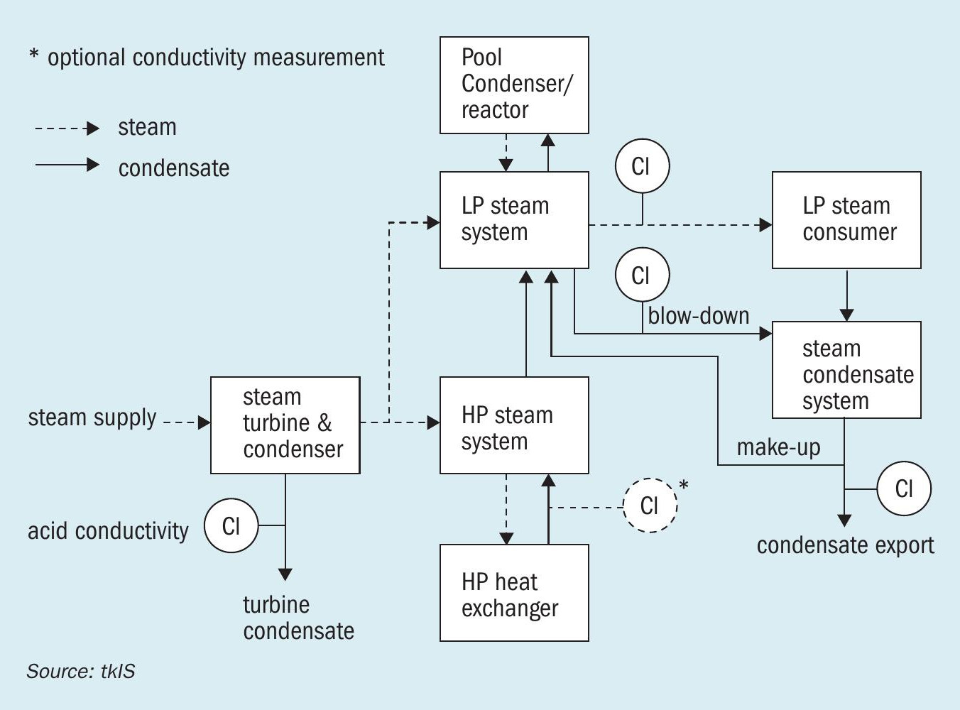
In a urea synthesis plant, the HP synthesis equipment is most vital for the operation of the plant. The synthesis is operated under severe process conditions and the synthesis solution contains amongst others carbamate, which is highly corrosive. This combination leads to challenging requirements for the used material in the urea synthesis. For the Stamicarbon urea process applied by thyssenkrupp Industrial Solutions (tkIS) the specifically developed duplex steel Safurex® is used as liner on the carbon steel pressure carrier for the HP synthesis equipment to withstand these harsh process conditions. A part of the HP synthesis equipment is energetically integrated to the carbon steel steam system of the urea plant via tube bundles. Here, MP steam is used as a heat source in one equipment and LP steam is generated in the tube bundle of another equipment. Even though a material failure of the tubes is very unlikely and had not yet occurred for Safurex® tubes, the effect thereof would be very severe. In the case of a tube leak, the whole carbon steel steam system could be contaminated with highly corrosive carbamate solution which would eventually lead to a release of ammonia via steam vent or steam condensate export. In case of a tube rupture, the whole hold up of the synthesis could be emptied from the synthesis into the steam system and additionally the design pressure of the steam system could be exceeded. That is why safety valves are installed in the steam system for this case, which release the synthesis solution in case of a tube rupture into a dedicated collection system. In both cases carbamate in the steam system can easily be detected as an increase of conductivity, which is why tkIS plants are provided with online conductivity analysers to closely monitor this parameter as shown in Fig. 4. This allows the detection of any leakage into the steam system or tube failure very early and prevents ammonia release to the atmosphere by blocking in the entire steam system.
However, a detected increase in conductivity is not necessarily correlated to a failure of an HP urea equipment as shown by the following two examples which occurred during the commissioning of tkIS urea plants. Both times, the conductivity analysers gave similar indications, but in the end there were completely different reasons for this and none included a failure of the HP equipment:
The first case happened during the commissioning of a urea plant in 2011. The analyser on the steam side of the HP heat exchanger showed a rapid increase of conductivity. Subsequently, the conductivity in the downstream systems increased as well. First a tube leakage in the HP heat exchanger was assumed, but the measured conductivity was much lower than could usually be expected for that case. Additionally, the laboratory analysis showed only an increase of the ammonia concentration and no increase in carbon dioxide concentration, which is expected in case of a tube leakage. Together with our client it was decided to keep the synthesis in operation as long as the conductivity stayed below a certain threshold while, in parallel, a root-causeanalysis was carried out.
After extensive sampling, it was found that the reason for the conductivity increase was not within the urea plant, but a consequence of a leaking heat exchanger in the upstream ammonia plant which provides steam to the urea plant. The conductivity analyser at the turbine condenser of the CO2 compressor turbine inside the urea plant did not indicate contamination of the inlet steam, because it was just measuring the acid conductivity and was unable to detect ammonia.
The second case happened during first start-up of a urea plant in 2017. A while after feed-in, the conductivity in the LP steam system started to increase. A consecutive increase of the conductivity in the condensate blow-down and after that in the condensate system could be detected within 15 minutes. The steam system was blocked-in by an automatic plant-trip and it was decided to consequently block in the whole urea synthesis. Lab samples which were taken immediately after plant shutdown confirmed the high conductivity and showed that ammonia as well as carbon dioxide were present in the steam and condensate system. Considering the lab results and because there was no increased conductivity in the condensate of the steam turbine – unlike the first case, here total conductivity was measured and not only acid conductivity – a cause outside of the urea plant could be excluded. The sequence of the conductivity increase detected by the online analysers together with the ammonia and carbon dioxide in the steam system implied that there had been a failure of one of the HP equipment. To inspect the HP synthesis equipment, it had to be drained, purged, flushed and cooled down in order to enter it, which was a time consuming procedure. But inspection and leakage test of both equipment, including a huge number of the combined almost 4,000 tubes, showed no failure. So the search was extended to all non-HP equipment connected to the steam system, which operates at higher pressure than the steam system. Here backflow would theoretically be possible in case of a material failure.
Normal process conditions are required to detect leakages in the LP equipment downstream of the synthesis, therefore it was decided to restart the plant and locate the leakage with an extended sampling schedule and some additional sampling points for manual sampling. Again, a conductivity increase was detected by the online monitors. However, with the additional sampling, the source of the carbamate contamination could successfully be attributed to the low pressure carbamate condenser (LPCC). This LPCC is operated by tempered cooling water of a closed cooling loop filled with steam condensate with a bleed stream to the steam condensate system. Thus, a leak to a cooling system was the reason for the high conductivity in the steam system. After the repair of the condenser and restart of the plant, no further issues with the conductivity in the steam and condensate system occurred.
The sequence of conductivity increase detected by the online analysers had not been reflecting the real sequence in the second case. The incorrect sequence was a consequence of different response times of the online conductivity analysers, due to different lengths of sampling tubing.
Both cases show that similar indications of process parameters are not necessarily caused by similar failures. Experience in engineering as well as in commissioning was the key success factor to find the root cause of the defects in due time for both cases enabling rectification and ensuring commissioning in time.
1,725 t/d urea project in Indonesia for Petrokimia Gresik
PT Petrokimia Gresik (PG) in Indonesia has been producing ammonia (1,350 t/d) and urea (1,400 t/d) for more than 20 years and in the past two decades has also intensely developed its NPK fertilizer production, which has become one of its core businesses.
Recently, the demand for NPK fertilizer has increased significantly, exceeding PG’s production capability. The demand for urea has also grown to approximately 1,100,100 t/a in East Java province of Indonesia, while PG was only able to supply 460,000 t/a of urea. In addition to this, most of the ammonia used as a raw material for NPK fertilizer production was imported and its high price had a big impact on the production cost of the fertilizers. For these reasons, PG decided to build a new ammonia and urea plant, to meet the increased demand and to reduce production costs4 .
The new project (Ammonia Urea 1B Project) consists of 2,000 t/d of ammonia and 1,725 t/d of prilled urea. Wuhuan Engineering Co., Ltd. (WEC) and PT Adhi Karya (ADHI) were awarded the EPC contract on a lump sum turnkey (LSTK) basis utilising technology licenses from KBR and Toyo Engineering Corporation (TOYO).
WEC, the EPC consortium leader, had the overall responsibility for the ammonia and urea plant, while ADHI’s scope was the utility units including urea product handling facilities. The service relating to the outside battery limit of this project (i.e. raw water supply, liquid ammonia storage, off-site piping, steam supply, and electricity supply) was the scope of other independent utility suppliers.
Initial start-up
During the initial start-up, a leakage from the lining of the reactor occurred unexpectedly due to a minor weld imperfection of a weld line between lining plates which cannot be detected by conventional non-destructive testing during manufacturing. Therefore, the urea plant was shut down immediately for repair. TOYO concentrated intensively on its repairing work and the urea plant was ready for start-up again in ten days. To avoid the recurrence of this problem, TOYO developed a special NDT for inspection of weld lines, which has already been applied in current on-going projects.
After the successful repair, from start-up it took only seven hours from raw material feed to the urea plant until first urea production. The readiness test was then performed in line with the requirement of EPC contract to ensure the urea plant could run at minimum 80% load, which was successfully completed in June 2018. However, after the readiness test, it was decided to shut down the urea plant for 19 days. During this period, all pending items were resolved.
Following the shutdown the urea plant was put back into service and the performance test was conducted at 100% load for a period of one week to confirm all the guaranteed figures specified in EPC contract, such as the consumption of raw material and utility, the product quality, etc. A demonstration test was then carried out at 110% and 115% load plant load. The urea plant was quite stable even at such high plant capacity.
Plant performance
Since commercial operation of the plant started in August 2018, the plant reliability has been confirmed and the plant has been running almost continuously at 110% capacity and finally achieved 120%. After one-year operation from the handover, the first turnaround was conducted in July 2019. All equipment was carefully checked and the critical equipment was free from any damage.
Project challenges
Every project has its own characteristics and challenges. Some of the major challenges faced in this project are detailed below.
Plant location near residential area
The dedicated area given to build this plant was in close proximity (approx. 300 m distance) to a residential area. No activities had any impact on the neighbourhood. Steam blowing was problematic resulting in many complaints due to its noise and heat exposure. To minimise the complaints, steam blowing had to be conducted during daytime only, which prolonged the activity, beyond the original plan. Close coordination among all the parties was required to prevent any activities being cause for complaint. Furthermore, as the emission of process fluid to the atmosphere also directly impacts the residents, a flare was installed to overcome it.
PG’s young and inexperienced personnel
PG’s main personnel involved in this project were relatively young – most were below 25 years old with less than two years job experience. Therefore, PG hired a senior, retired, former employee of PG to transfer expertise and support the inexperienced personnel. PG also employed some technical experts from third parties who had extensive experience in the construction of grass-roots ammonia and urea projects. Their coaching and leadership significantly raised the knowledge of the young personnel to a higher level.
PG also utilised TOYO’s operating training simulator (OTS), which proved very useful to operators, speeding up the time to become familiar with the operation and to learn the basic operational philosophy of the urea plant. OTS’s interface was very similar to the real HMI and young operators were able to simulate operating the real plant under various situations: start-up, shut down, normal operation, and even abnormal conditions. The more they utilised the OTS, the more experience they gained.
Safety awareness
Since safety is the first priority for all activities, the close meeting was always held to discuss the concrete work plan, and it was briefed again at the site among all parties. Despite strict supervision by PG, some workers still broke rules, for example, there was a case where a worker took off his safety protection because he felt uncomfortable wearing it while working. Each work area leader, who was a role model for the workforce, had the strong mandate to ensure workers obeyed the rules.
Change of government regulation
Government regulation was one of the biggest uncertainties in the project execution stage. Changing of the regulation related to “the import of steel and alloy”, “the custom clearance”, and “the labour law” caused three months delay to the project schedule. In the end, the EPC contract was revised to extend the period of the project by eight months, taking all unexpected circumstances into account.
Quality control (QC) of manufactured equipment
The competent and experienced inspectors, hired by PG from a third party, played an important role ensuring that the quality of the equipment satisfied the requirements based on international codes and standard. Most of the inspection activities were performed by them and no defects were observed throughout the project.
Supply of electricity and steam
The supply of electric power and steam for the plant was out of scope in this project, which means it was supplied from outside plants built newly by other independent utility suppliers. The project to build new power and steam plants commenced at the same time as this project, but unfortunately progress of their project was delayed. The overall project schedule also had to be delayed because each activity related to steam and power was suspended due to this reason. To minimise the delay, PG decided to shutdown PG’s existing plants in sacrifice, and transfer steam and power to the new ammonia and urea plant.
References