Nitrogen+Syngas 366 Jul-Aug 2020

31 July 2020
Reducing the CO2 intensity of hydrogen production
LOW CARBON HYDROGEN
Reducing the CO2 intensity of hydrogen production
There is an urgent need to limit the rise in global temperatures to avoid severe environmental and societal impact. This can be expressed as a target to achieve net zero carbon emissions by 2050. The provision of decarbonised hydrogen at scale is an essential step in helping to achieve net zero. Johnson Matthey’s Low Carbon Hydrogen (LCH) technology permits the needs of scale and urgency to be met. J. Pach of Johnson Matthey presents a serious response to a serious threat.
Johnson Matthey’s vision is for a world that’s cleaner and healthier, both today and for future generations. As a global leader in sustainable technologies, Johnson Matthey (JM) uses cutting-edge science to create solutions with its customers that make a real difference to the world around us.
Global average temperatures are rising above pre-industrial levels, with severe environmental and societal repercussions. There is an urgent need to deploy technologies at scale that will arrest this rate of rise by reducing greenhouse gas (GHG) emissions and contribute towards net-zero carbon emission-based economies by 2050.
Nearly 50% of global GHG emissions are produced by industry and in connection with the provision of fuel for generation of heat and power. The provision of decarbonised hydrogen is essential to achieving significant reductions in emissions from these segments.
The use of JM’s LCH technology facilitates the production of decarbonised carbon at scale using proven technology.
Hydrogen production
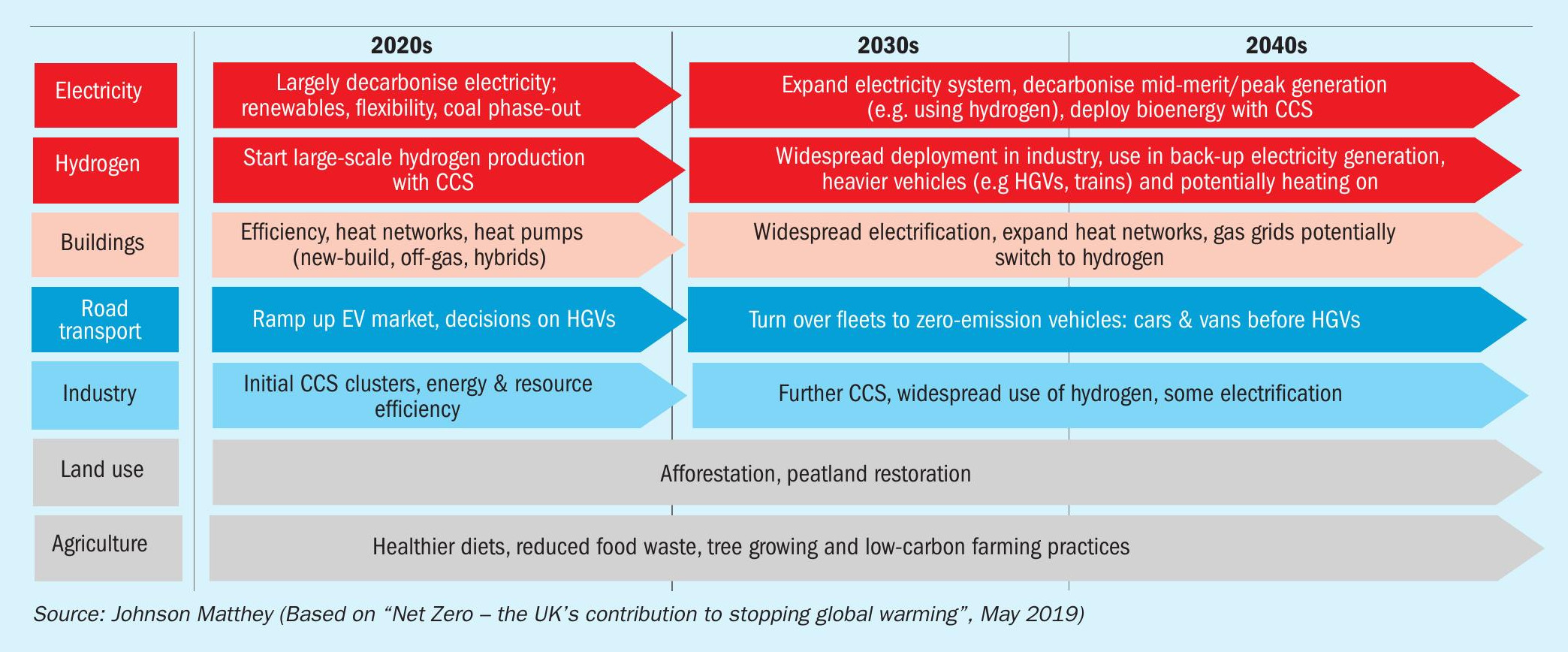
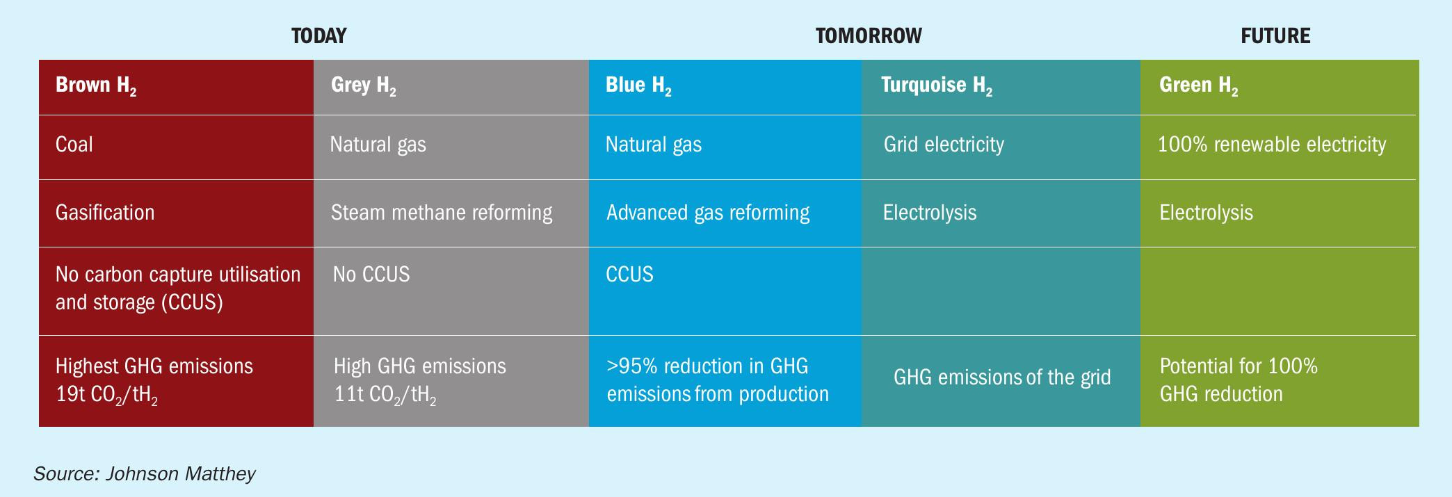
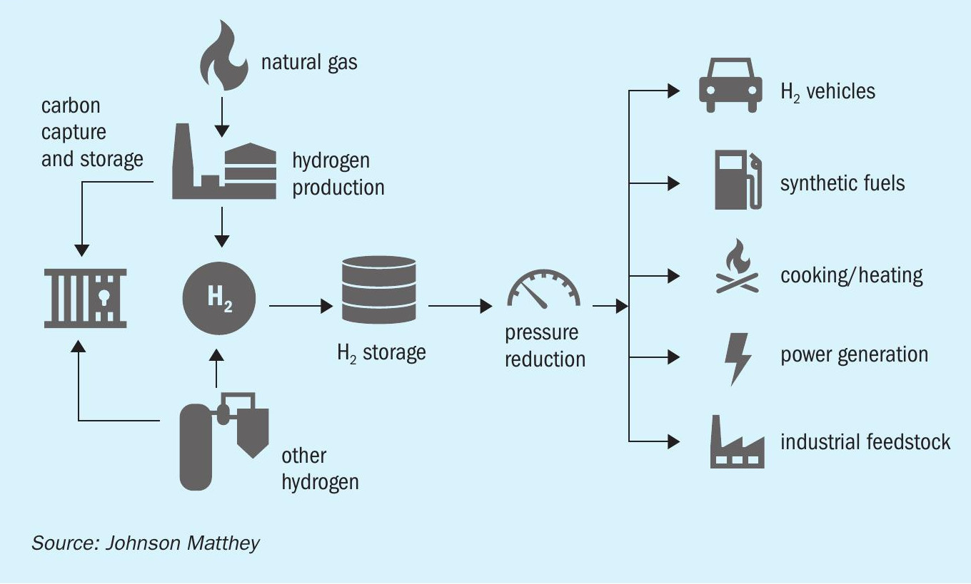
There are numerous strands of activity that need to be addressed to mitigate or reduce carbon emissions (Fig. 1). The key takeaway from the chart in Fig. 1 is the aggressive timescale over which each of these issues must be addressed. The ultimate goal is the most efficient use of the world’s natural resources with minimal associated environmental impact. In the long term this will mean the large-scale generation of hydrogen from renewable energy and electrolysers. However, much work is still to be done to realise an acceptable cost base for deployment of this technology, at the scale required, in the short to medium term. The hydrogen provision roadmap is summarised in Fig. 2. Although the fundamental driver is emissions reduction at scale, a blend of decarbonised technologies will be required due to location and cost drivers. There will also be a transition to ever greener hydrogen over time.
Today, hydrogen is predominantly made by steam reforming of natural gas, which produces carbon dioxide as a byproduct.
The reforming reaction for methane is:
CH4 + H2 O CO + 3H2 (1) ΔH = +206 kJ/kmol
In addition, the water gas shift reaction generates further hydrogen:
CO + H2 O CO2 + H2 (2) ΔH = -41 kJ/kmol
Around 55 million tonnes of hydrogen is produced globally each year. The majority of this is produced from steam methane reforming and partial oil oxidation with the remainder produced from coal gasification and electrolysis.
Around half of current hydrogen consumption is in the petroleum refining and recovery sector, in which hydrogen is used to crack heavier oils into lighter oils for use as petroleum and petroleum products. The second largest use of hydrogen is in the production of ammonia for fertilizers, in which hydrogen is combined with nitrogen as part of the Haber-Bosch process. The remaining 10% of hydrogen use is split across the food, methanol, metals and electronics industries.
Growth is forecast across all these markets and, to reduce GHG emissions to acceptable levels, substantial reductions in carbon dioxide emissions associated with hydrogen manufacture are required over the short to medium term. In addition, displacement of methane by pure or blended hydrogen for industrial and domestic purposes will lead to a significant increase in the demand for hydrogen. A low carbon solution for hydrogen production is therefore required to minimise climate change.
There are three main options for producing low-carbon hydrogen:
- electrolysis using low-carbon electricity;
- bioenergy with carbon capture and storage (CSS);
- natural gas reforming with CCS.
Electrolysis and bioenergy are likely to be limited by resource availability and the economies of scale, at least in the near term. In contrast, the production of hydrogen from natural gas reforming with CCS is not resource-limited in the same way and can be deployed at an impactful scale to deliver low carbon hydrogen in which more than 95% of the carbon dioxide is captured. Hydrogen produced in such a manner is often termed ‘blue’ (Fig. 2).
Conventional hydrogen production
The majority of the world’s hydrogen is produced in a steam methane reformer (SMR) in a flowsheet similar to that illustrated in Fig. 3.
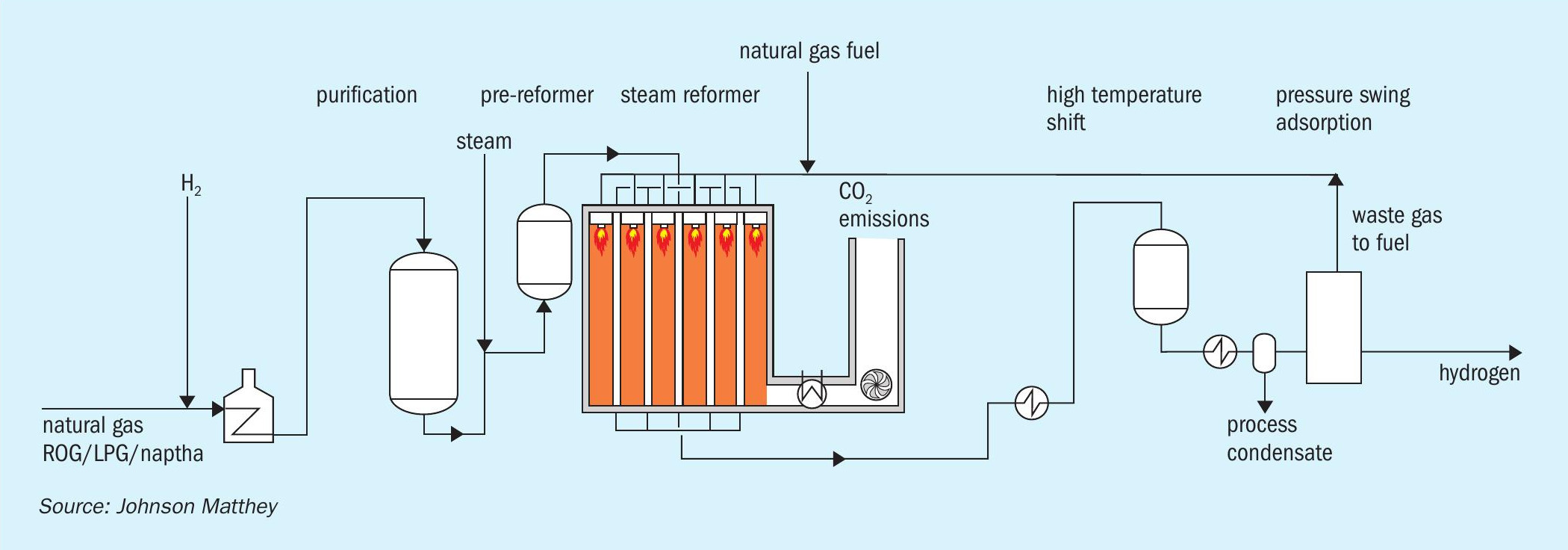
Natural gas is purified in a hydrodesulphurisation step in which organo-sulphur compounds are hydrogenated to form hydrogen sulphide which is then removed by absorption onto zinc oxide.
The SMR is a large refractory-lined box containing many pressurised tubes in which natural gas is converted to hydrogen across a nickel-based catalyst per equations (1) and (2). The reaction produces a mixture of hydrogen, carbon monoxide and carbon dioxide, which is often termed “syngas”. The steam reforming reaction is endothermic, so a source of heat is required and this is obtained by burning additional natural gas. Various waste gas streams can also be used. Depending on the flowsheet and final product, typical reformer exit temperatures are usually in the range 700-930°C.
The syngas leaving the SMR then passes across one or more beds of water gas shift catalyst which increases hydrogen production (equation 2). The water gas shift reaction is exothermic and energy is recovered by steam generation and as boiler feed water pre-heat.
SMR flowsheets have been optimised over many years and, with production capacity ranging from 1 to 330 kNm³/h of hydrogen, have become the technology of choice for the production of high purity hydrogen on a reliable basis. However, very few hydrogen plants capture carbon dioxide emissions.
If hydrogen is to play a role in reducing the impact of climate change, it needs to be produced with concomitantly low carbon dioxide emissions which, when using natural gas as a feedstock, implies coupling it with carbon capture and storage (CCS). The combustion process in an SMR produces carbon dioxide at low concentration and at atmospheric pressure which inevitably leads to high capital cost (capex) due to the low partial pressure of carbon dioxide. In addition, post-combustion capture of the carbon dioxide and/or the use of process-produced hydrogen as the fuel in the reformer introduce significant efficiency losses.
Accordingly, for blue hydrogen to be cost effective, high purity hydrogen must be produced in a process, which also makes high pressure/high purity carbon dioxide, without an excessive capital or variable cost penalty.
Low carbon hydrogen technology
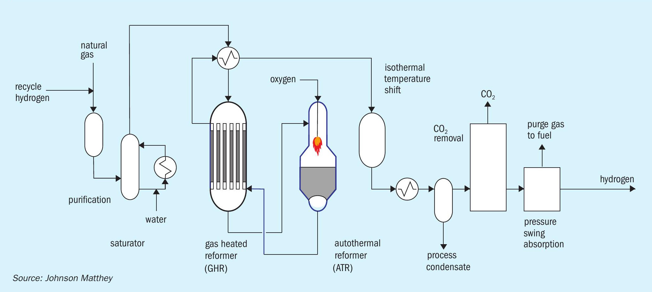
In JM’s low carbon hydrogen (LCH) flowsheet (Fig. 4), heat is recovered at maximum exergy (the highest possible quality) with commensurate efficiency benefits. This is achieved by coupling a gas heated reformer (GHR) with an auto-thermal reformer (ATR). The main difference between LCH and SMR flowsheets is that the energy used to drive the steam methane reforming reaction is provided by introducing oxygen to the ATR rather than burning natural gas in an SMR. At the scales envisaged, the oxygen can be obtained from an air separation unit (ASU).
By-production nitrogen from the ASU could be utilised to feed an ammonia loop.
ATRs are already used in the production of syngas and are an integral part of most modern schemes for production of methanol and of liquid fuels from Fischer-Tropsch processes. These plants are very large and demonstrate thatthe technology can produce hydrogen at large scale, thereby eliminating scale-up risk.
GHRs have operated on a commercial basis for over 100 cumulative plant years and have demonstrated best in class reliability. The technology has been scaled to facilitate a 5,000 t/d methanol project in the US. In 2016, JM’s technological breakthrough was awarded the top prize at the IChemE Global Awards (Outstanding Achievement in Chemical and Process Engineering). Therefore LCH, with its high degree of technology readiness, is optimally placed to address the current need to deploy best-in-class low carbon hydrogen production both at the scale required and with immediate effect.
Purified natural gas is pre-heated and reformed in the GHR before entering the ATR. In the first stage, the GHR, around 30% of the hydrocarbon feedstock is reformed by reaction with steam to form syngas. In the second stage, the ATR, oxygen is added and reacts with some of the partially-reformed gas to raise the process gas temperature to more than 1,500°C. The resulting gas then passes across a bed of steam reforming catalyst inside the same reactor for further reforming. Since the reaction is limited by equilibrium, operation at high temperature and steam flows minimises the methane content of the product gas which, in turn, minimise overall carbon dioxide emissions. The hot gas exiting the ATR passes back through the GHR shell side providing the heat necessary to drive the reforming reaction in the GHR tube side. The gas then passes through an isothermal water gas shift reactor and carbon dioxide removal, before final purification in a pressure swing adsorption (PSA) unit.
Comparison of the technologies
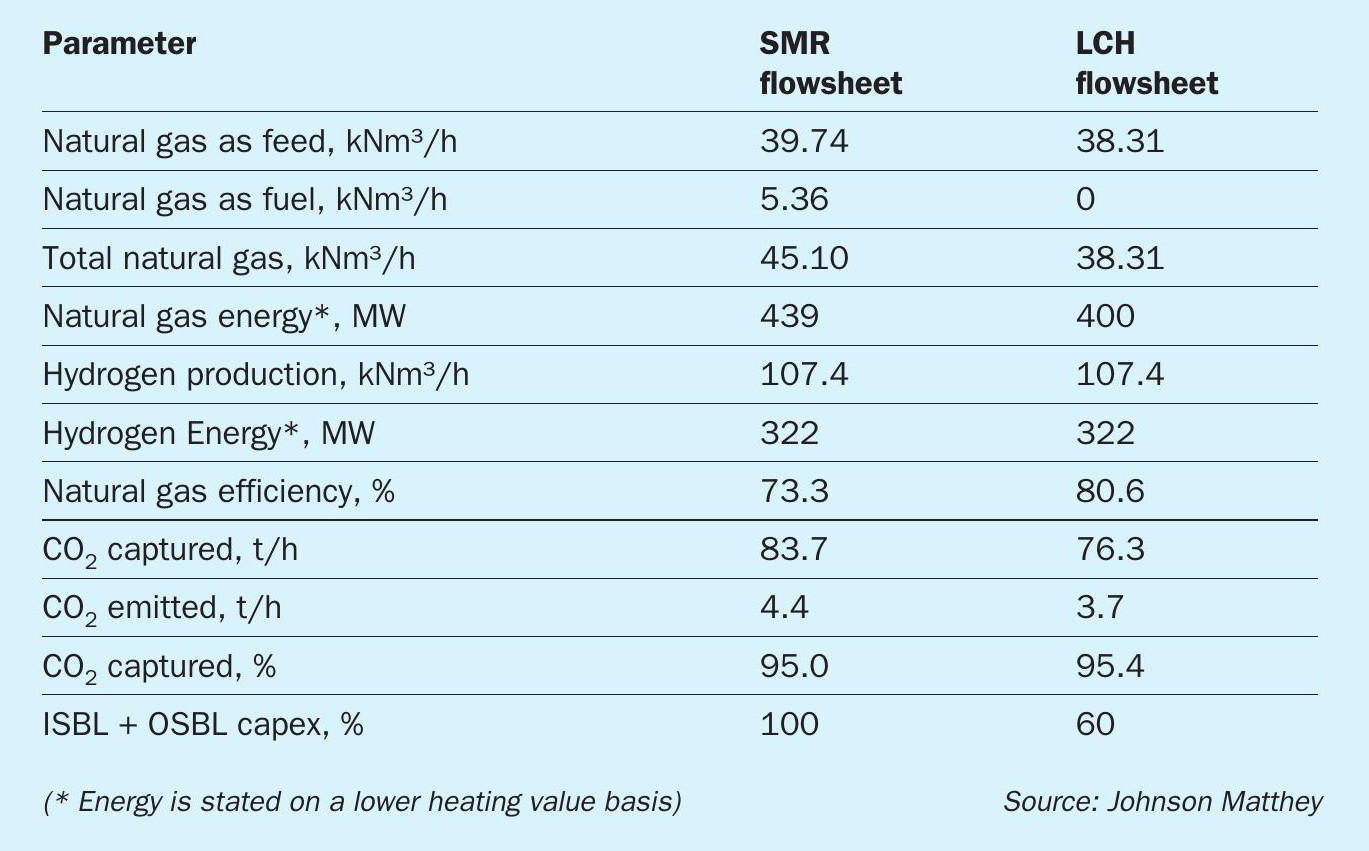
The advantages of an LCH flowsheet over an SMR flowsheet include (Table 1):
- Inherently greater efficiency: High grade heat is recycled back into reforming reactions at a higher quality (exergy) than is possible in an SMR flowsheet which degrades the energy quality (exergy) by raising medium pressure steam as a heat transfer medium;
- Improved feedstock conversion efficiency: The use of the gas heated reformer in series with the ATR means that reforming reactions are conducted at a higher temperature, leading to higher conversion of hydrocarbon feedstock to product hydrogen. This reduces the amount of carbon dioxide produced per unit of hydrogen made.
- Reduction in capex and opex: In the LCH flowsheet, all carbon dioxide is contained within the product stream at relatively high pressure. High purity carbon dioxide can therefore be removed easily using standard carbon dioxide removal technologies. This leads to a significant reduction in capex and opex compared to the alternative of carbon dioxide recovery at low pressure, as is the case with flue gas carbon dioxide recovery in an SMR based flowsheet. In addition, the reduction in the amount of carbon dioxide produced per unit of hydrogen made leads to a reduction in CCS costs and carbon tax. l Ability to utilise renewable energy: The energy required for the air separation unit and for carbon dioxide compression can be provided by renewable electrical energy.
LCH technology can therefore accommodate renewable energy import and provide a flowsheet with dramatically reduced greenhouse gas emissions, lower capital cost and lower natural gas consumption.
Deployment of LCH technology
LCH technology has been independently assessed to be the most cost-efficient technology capable of achieving greater than 95% carbon capture at scale and it forms the cornerstone of a number of projects in the UK that seek to decarbonise regional industrial clusters (Fig. 5). One such project is Hynet which seeks to decarbonise a proposed industrial hydrogen cluster in North West England
If a cluster is located close to an existing ammonia plant, additional synergies are possible
- carbon dioxide that is already being extracted from the ammonia plant can be sent to the CCS facility;
- Tte LCH plant can be used as a source of additional, low carbon hydrogen for ammonia manufacture;
- by-product nitrogen from the ASU as a source of additional nitrogen for ammonia manufacture.
Conclusion
As businesses, and as societies, we face a serious threat in the guise of GHG emission driven climate change. Decarbonised hydrogen is essential for achieving net zero carbon emissions. Johnson Mat-they’s LCH, proven technology with flexibility to integrate ever increasing amounts of renewable energy into its flowsheet, stands ready to play its part.