Sulphur 396 Sept-Oct 2021
30 September 2021
Extending the life of sulphuric acid plants
SULPHURIC ACID TECHNOLOGY
Extending the life of sulphuric acid plants
Chemetics describes a variety of ways to extend the life of sulphuric acid plants. Debottlenecking, emissions reduction and/or energy recovery projects require a systematic, phased approach to maximise the potential of economic and operational benefits to the owner.
A systematic phased approach to debottlenecking
Sulphuric acid plant operators are faced with the increasing challenge of extending the service life of its existing equipment after initial start-up. As the plant ages, equipment wears out and requires routine maintenance or replacement. Quite often, there is a need to debottleneck the plant to meet future demands of acid production, metals production, etc. Environmental regulations continue to evolve which results in requirement to reduce emissions such as SO2 and liquid effluent as well as increase energy recovery to reduce the plant’s environmental footprint.
Usually, plant debottlenecking involves a combination of the following objectives:
- Increase production capacity by increasing gas flow to the sulphuric acid plant or by an increase in SO2 concentration to the plant.
- Reduce SO2 and other emissions by increasing conversion of SO2 to SO3 or tail gas treatment before the plant stack.
- Reduce utility/energy consumption by reducing plant pressure drop, cooling water consumption, and increasing heat recovery.
- Improve operability and flexibility by increasing turndown ratio, faster equipment ramp-up, etc.
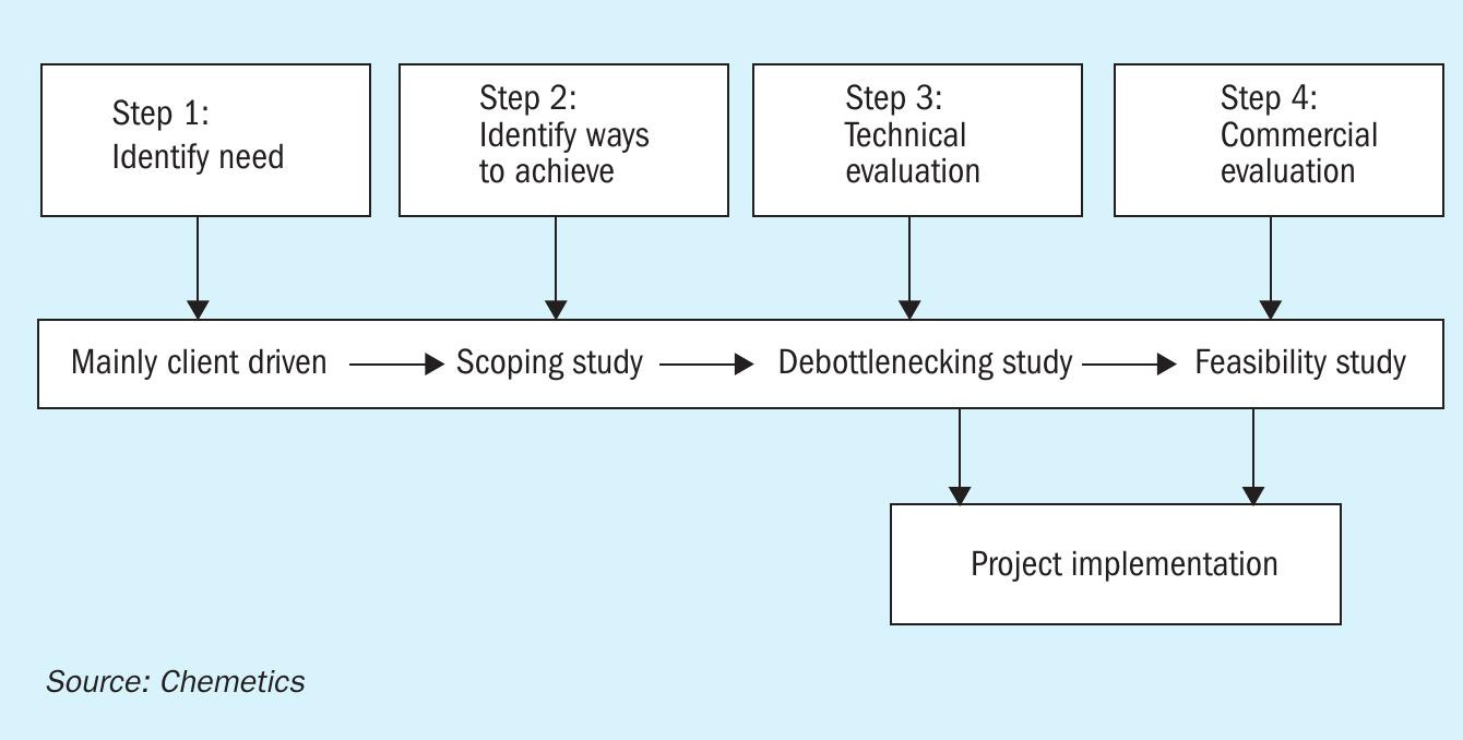
In most situations, a combination of these requirements must be implemented within stringent timeline restrictions such as smelter turnaround schedules. Sometimes these objectives conflict with each another. For example, increasing SO2 conversion might result in more catalyst volume being required which in turn will increase pressure drop (thus energy consumption) of the plant. Therefore, it is critical for operators to debottleneck the plant using a holistic (plant wide) approach and thoroughly evaluate options based on technical and economic merits before implementation. Fig. 1 shows Chemetics’ proven stepwise approach to plant debottlenecking.
The first step is for the plant operator to identify the need and objectives of the retrofit. This can be specific to the plant operation parameters (e.g. increase acid plant capacity by 100 t/d to match future acid consumption on site with a specific cost per tonne). It can also be driven by other opportunities, such as “Instead of replacing the existing converter with an in-kind design, what could be achieved with a reasonable investment in a new state-ofthe art converter design?”.
In step 2, a scoping study should be performed to identify different technologies and methods to achieve the objectives identified in step 1. At this step, only high-level process evaluation is performed (e.g. increase catalyst loading in converter versus install a new tail gas scrubber) with economic evaluation limited to “order of magnitude” level of detail. This enables the plant owner to select the solution(s) for a more detailed evaluation in the next step. This also eliminates the risk of spending time and money to evaluate options that have little or no merit and should not be evaluated further.
In step 3, a small number of options (usually two or three) will be studied based on actual equipment limits using simulations and actual plant operation data. At this level economic evaluation should be based on major equipment costs and factored installation costs. Economic evaluation should be more detailed (typically AACE class 4/5 or +/40-50% range). At the end of this step engineering should be advanced with enough detail for the purpose of final commercial evaluation and/ or basic engineering (step 4).
In step 4, the economic evaluation will usually be limited to a single configuration and incorporate elements of basic engineering where they are critical to the feasibility of the project. Specific equipment layouts and construction sequence should also be evaluated at this stage. Cost evaluation will be based on actual vendor quotations with an accuracy of around +/10% to 20%. This final step usually will become the design input for project approval and implementation.

Due to limitations in budgets and time limits allowed in a shutdown to implement the plant modifications, many debottlenecking projects are implemented in phases. The phased approach (sometimes spread out in multi-year implementation) will result in higher construction costs but will reduce production losses. Sensitivity analysis to balance capital cost expenditures against revenue lost due to downtime will determine if a phased implementation is suitable.
The descriptions above provide a general overview on what objectives should be achieved for each step. It is important for the technology supplier to tailor the deliverables for each study phase to the owner’s specific requirements for their capital and project approval process.
Equipment replacement
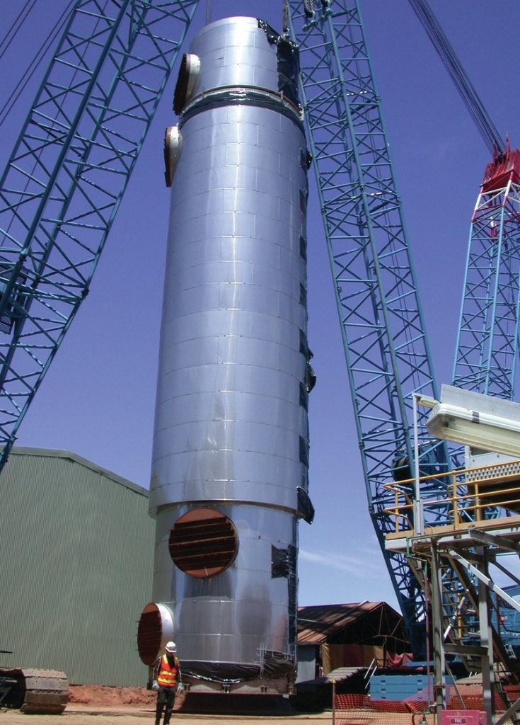
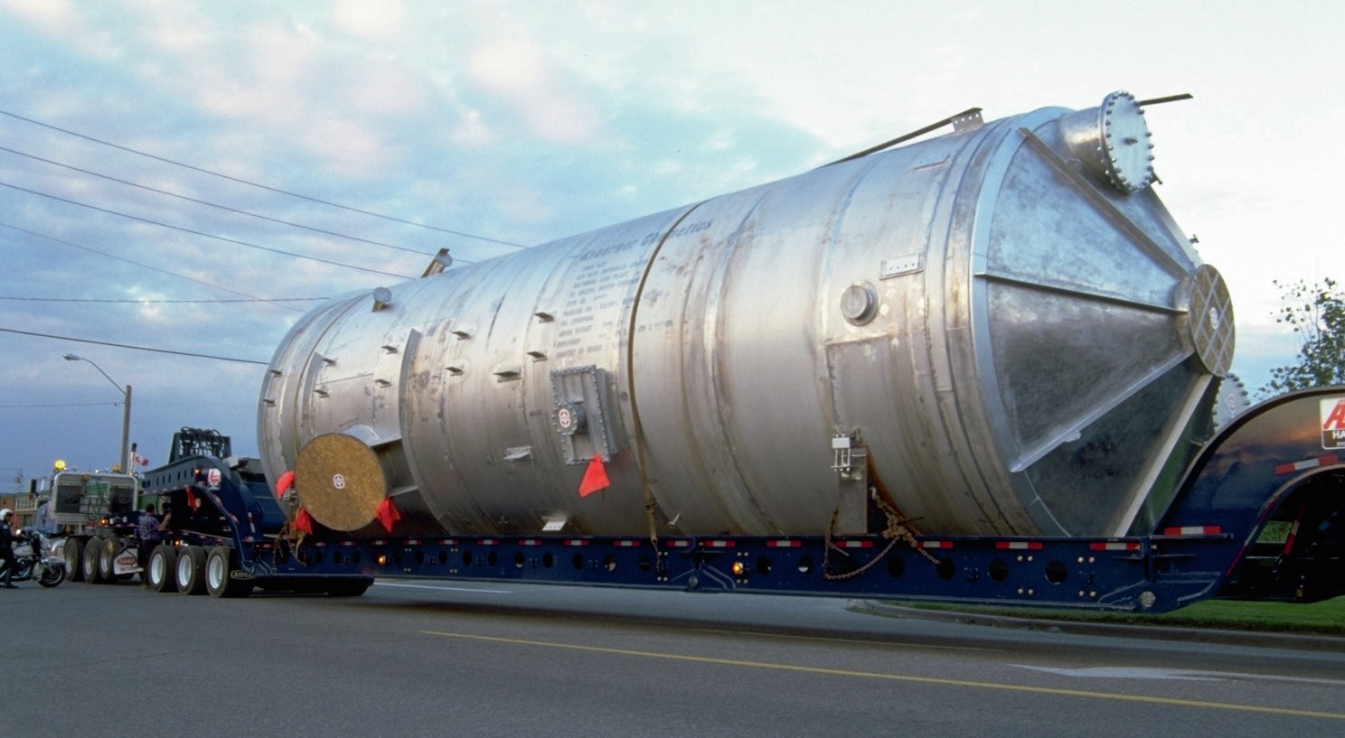
Replacing old, fouled equipment with modern, properly designed sulphuric acid equipment is a key strategy to extend the life of an existing plant. For instance, modern radial flow exchangers (Fig. 2) can be used to dramatically reduce plant pressure drop. This has the benefit of increasing plant capacity without additional blower power. More than 60% of Chemetics’ designed radial tube pitch heat exchangers are used for plant debottlenecking. Similarly, installing new alloy (or brick lined) acid towers to replace old and worn-out, brick-lined vessels is also a common feature in retrofit projects where pre-erection of long lead items is not possible due to existing plant layout constraints. In this case a fully fabricated alloy acid tower (Fig. 3) can be dropped into the existing tower location with a relatively short turnaround time.
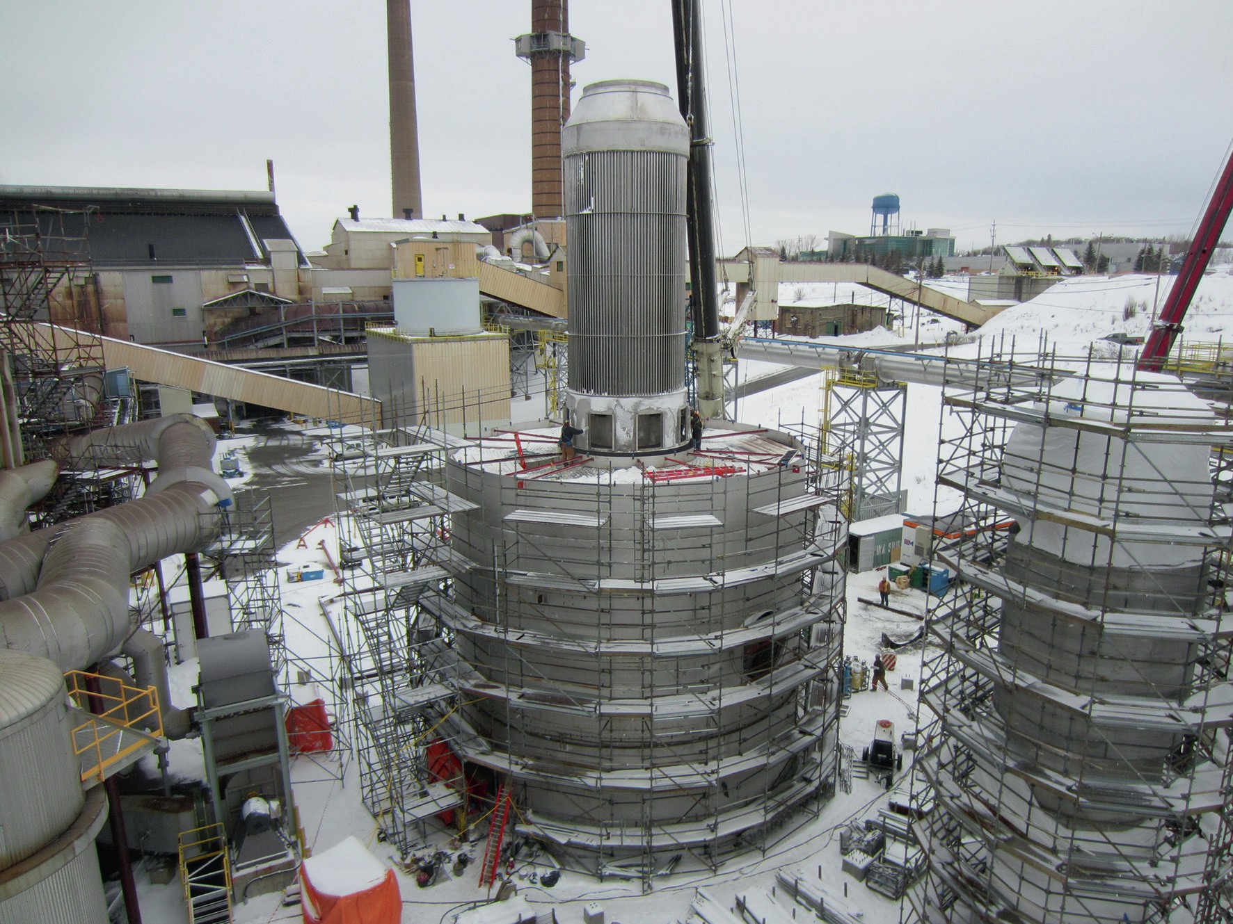
Replacing an existing post and grid converter with an all stainless, fully welded converter is another common strategy to unlock performance within an existing acid plant. Modern converters by Chemetics feature a fully welded design to eliminate hot gas bypassing, radial gas flow across catalyst beds for improved gas distribution, circular duct transitions to eliminate possibilities of duct cracking and shorter preheat time. Internal gas exchangers eliminate hot ducting and provide substantially lower maintenance costs. Since radial flow stainless steel converters are much lighter than traditional carbon steel, refractory lined units. For smaller converters it is possible to lift a fully fabricated stainless steel converter into place instead of traditional field construction (Fig. 4), resulting in significantly reduced downtime. Another strategy that has been practiced by Chemetics is to construct the converter using prefabricated modules, then each level of the converter is lifted into position. This can result in reduction in field labour costs by 75%.
Heat recovery in sulphuric acid plants
The sulphuric acid process is highly exothermic and to maintain heat balance, excess heat will need to be removed. Heat recovery is putting this heat into any useful purpose. First and foremost, recovering heat from high temperature sources such as the sulphur or regeneration furnace and converter to generate high pressure steam for power generation are widely practiced. However, other areas in the acid plant still have large amounts of lower grade heat and are typically disposed in cooling water. Converting this low-grade heat into lower pressure steam or hot water is commonly done and should be considered for the plant site.
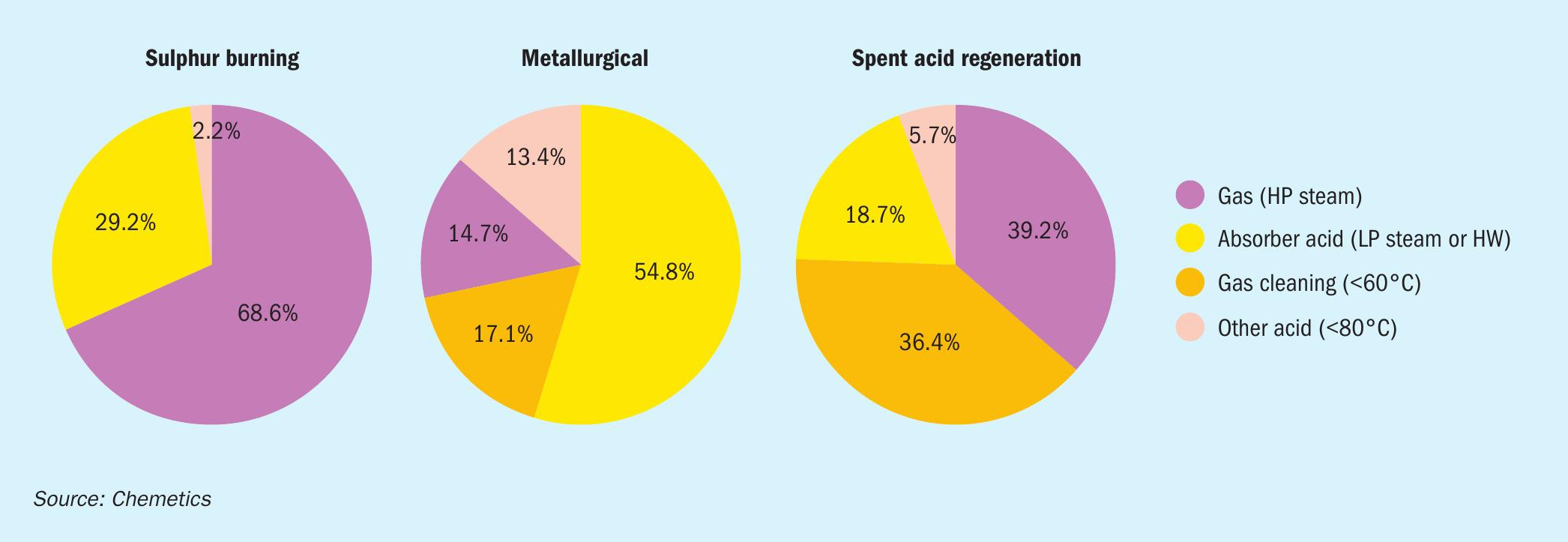
The amount of recoverable energy depends on the plant type (sulphur burning, metallurgical, spent acid regeneration). Fig. 5 shows typical recoverable energy profile for different types of acid plants. It should be noted that the heat recovered can be used inside the acid plant for items like boiler feedwater preheating or low-pressure steam addition. Or outside the acid plant battery limits, for phosphoric acid concentration, district heating, water desalination, and other local use such as raffinate heating in a hydromet complex.
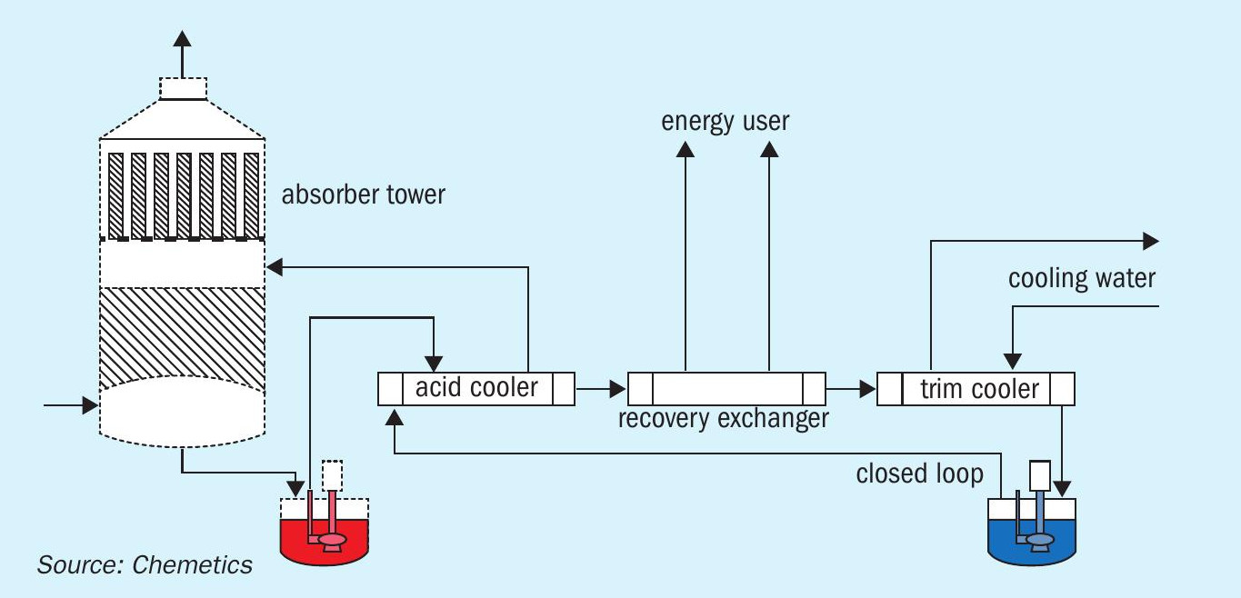
It is important that the system is reliable as the value of heat recovered has much less value than the value of the acid produced. If the system is unreliable, the cost of lost production in acid will far exceed the value in energy recovered. If maximum reliability is required indirect (closed loop) heat generation is recommended (Fig. 6).
In the flow scheme in Fig. 6, the hot water produced can be used for boiler feed water preheating, a municipal heating system, or for an evaporation system such as a multiple effect distillation (MED) system for a desalination plant. One of the major benefits of such a system is that the closed loop circuit uses demin or desalinated water. This clean water will result in high reliability due to its low fouling tendency.
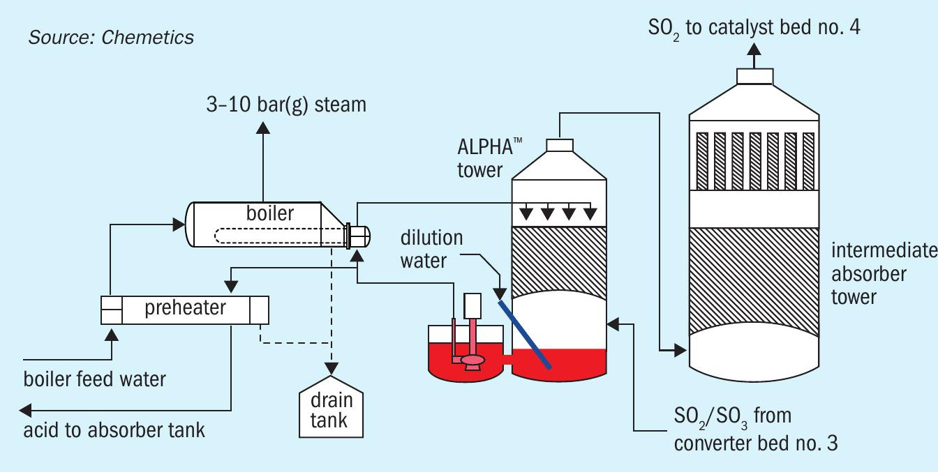
In the case of recovering low grade heat to produce medium pressure (4-10 bar(g)) steam, it is critical to consider the safety and reliability of such a system. The process conditions to produce MP steam requires the equipment to handle high temperature acid (190-210°C) which has a very high corrosion potential. If the system is down, the cost of lost production will very quickly exceed the value of the additional low-pressure steam produced. Fig. 7 shows a schematic of Chemetics’ ALPHA™ system which allows for the system to be shut down without forcing the acid plant to shut down, as well to ensure high reliability of acid production.
Emissions reduction
As environmental regulations become ever tighter for sulphuric acid plants, plant operators continue to look at new ways to reduce stack emissions such as SO2 and NOx. In addition, there is an increased emphasis in looking at reducing emissions during transient situations such as plant start-up and shutdown.
In general options for SO2 emission reduction include the following options:
- improve the performance of the existing contact process by using higher efficiency catalyst, optimise catalyst loading and operating temperatures;
- convert old single contact single absorption (SCSA) plants to the double contact double absorption (DCDA) process;
- install a chemical tail gas scrubber; l install a regenerative tail gas scrubber;
- application of a catalytic tail gas treatment process.
Improving catalyst formulations and adjusting catalyst temperatures can sometimes be achieved without changing the equipment. With the additional benefit of no additional effluent generation. However, the pressure drop will likely need to be increased which results in higher energy consumption and potential reduced acid production in the plant.
For a typical 3:1 DCDA sulphur burning acid plant, the SO2 emissions limit is typically limited to ~100 ppmv. With an additional fifth bed (3:2 configuration) the SO2 emissions can be reduced to ~50 ppmv range.
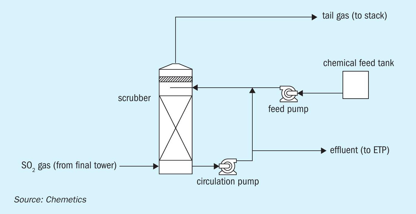
To further reduce SO2 emissions additional tail gas treatment will be required after the contact plant. Chemical scrubbers such as caustic (NaOH), hydrogen peroxide (H2 O2 ) and ammonia (NH3 ) are widely used as the installed cost of such a system is relatively low, and they are able to reduce SO2 emissions down to approximately 20 ppmv (Fig. 8). However, there are many downsides to such systems, mainly dealing with storing and introducing additional chemicals on site, a visible plume (tail gas leaving scrubber will be saturated with water), additional energy consumption due to pressure drop in scrubber, and handling/treatment of effluent generated.
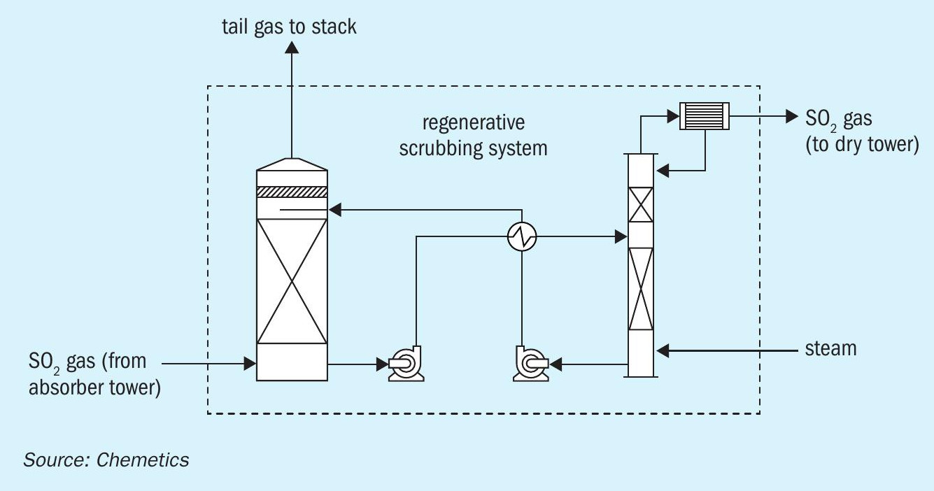
An alternative to traditional chemical scrubbers, regenerative scrubbers recover SO2 in the tail gas by first absorbing the SO2 through the reversible reaction with an amine-based scrubber solvent (Fig. 9). Then the SO2 gas is recovered by stripping the SO2 -rich solvent in a secondary column using steam. This concentrated SO2 gas produced can then be recycled back to the contact plant. Regenerative scrubbers have the advantage of opex not being impacted by inlet SO2 concentration, and the ability to recover SO2 gas for the acid plant. However, it is important to note that regenerative scrubbers require steam for solvent regeneration, as well as higher installed cost compared to chemical scrubbers.
Catalytic tail gas treatment can be used for SO2 emissions control. The traditional process is to use packed beds of activated carbon to slowly oxidise SO2 to SO3 . This process generates only weak acid which can be sent to the acid circuit as dilution water which turns SO2 into acid product value. The major downside is that traditional activated carbon used in this process has a very high pressure drop and large volumes of activated carbon are required which results in very large scrubber sizes.
Chemetics is offering an improved process that combines the catalyst activity of the activated carbon with the low pressure drop of a honeycomb packing. This process is offered under the name Chemetics Blacktail™ . This technology involves a proprietary process which combine activated carbon particles to a lightweight matrix of hydrophobic material resulting in a very thin material that can be shaped into the low pressure drop honeycomb structure.
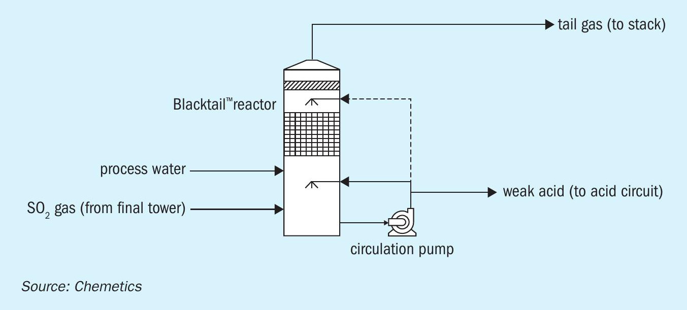
In the Blacktail™ process, tail gas from the contact plant enters the bottom of the tower where it is humidified with weak acid delivered through the sprays at the top of the Blacktail™ Reactor. The humid gas then enters the catalyst arranged in module layers which SO2 is absorbed into the surface of the activated carbon, which is then oxidised from SO2 to SO3 . The resulting SO3 reacts with the moisture in the gas to produce ~15 wt-% H2SO4 solution which drains to the bottom of the reactor and is sent to the acid circuit in the acid plant. The treated gas is discharged at the top of the Blacktail™ reactor and is sent to the plant stack (Fig. 10).
The key advantage of this technology compared to both chemical and regenerative scrubbers is that it generates no effluent, nor does it require continuous chemical consumption. The only by-product it produces is weak sulphuric acid which can be returned to the acid circuit for acid production. With very low pressure drop (up to 75% lower than equivalent chemical scrubber), the Blacktail™ can be applied in plants where the main blower has little or no spare capacity.
Summary
A systematic, phased approach to debottlenecking, emissions reduction and/or energy recovery projects maximise the potential of economic and operational benefits to the owner and eliminates the risk of spending time and money to evaluate options that have little or no merit and should not be evaluated in detail. Various techniques to accelerate tie-in schedule and minimising plant turnaround time including pre-fabrication and pre-erection of new equipment should be considered.
Replacing old and worn-out equipment with modern design sulphuric acid equipment will result in improved plant performance, increased reliability, longer plant up-time, and reduced on-going maintenance costs.