Nitrogen+Syngas 373 Sept-Oct 2021
30 September 2021
Waste to methanol
SUSTAINABLE SOLUTIONS
Waste to methanol
Johnson Matthey and MyRechemical have formed an alliance to commercially develop waste to methanol technology. In this article, two different approaches to waste disposal and chemical production are analysed: a post combustion scenario with waste incineration and hydrogenation of the CO2 recovered from flue gas to produce methanol, and a precombustion approach with waste gasification followed by conversion of synthesis gas into methanol.
Reduction of greenhouse gas (GHG) emissions in the industrial sector to mitigate climate change is a major challenge facing the global industrial and scientific community. Efforts and action in this community are underway through transformation of carbon-based fossil energy to a zero carbon footprint, the so-called energy transition.
This approach is re-shaping energy production by exploring more sustainable routes based on increased share of renewable energy, less intensive use of fossil resource, introduction of the circular economy concept, application of carbon capture in conventional process as well as measures aimed at increasing process efficiency.
A more sustainable use of resources has also been supported in the last few years by the European Commission (EC) through a policy stating that waste management should be improved and transformed into sustainable material management with a view to promoting the principles of the circular economy, enhancing the use of renewable energy, and providing new economic opportunities (EU Directive, 2018)1 . In this regard many accomplishments have already been achieved, as demonstrated by several ongoing projects aimed at valorisation of non-conventional feedstock such as solid, gaseous, or liquid waste source.
Arcelor Mittal completed construction of the first commercial plant in Europe aimed at re-use of the waste gases emitted from steelmaking for ethanol production. This plant will produce 80,000 million litres per year of ethanol2 .
Fulcrum has developed a commercial scale project to enable the conversion of municipal solid waste into low-carbon renewable transportation fuels, including jet fuel and diesel. This process combines gasification technology with Johnson Matthey (JM) and British Petroleum’s (BP) Fischer-Tropsch (FT) technology to produce renewable transportation fuels. Before feeding the system, municipal solid waste is pretreated to remove recyclable products and other material not suitable for processing. The resulting syngas then enters the FT process followed by upgrading step to a transportation fuel3 .
The above-mentioned examples demonstrate how the concept of a circular economy is already in motion and is currently reshaping many industries with the aim of waste valorisation.
Focusing on municipal solid waste (MSW), the current processes for residue plastics and the dry fraction of MSW, commonly known as refuse derived fuel (RDF), are mainly based on thermal valorisation for power and heat production followed by disposal in landfill. Although the efficiency of modern incinerators has increased, incineration does not recover any carbon or hydrogen, instead these components are fully oxidised to CO2 and water and discharged in diluted form into the environment through flue gas. Because of the resulting high GHG emissions, waste disposal is under the spotlight and carbon capture solutions are being investigated to mitigate the emissions from incinerators, to provide a more sustainable approach.
Huttenhuis et al.4 described an application of carbon capture and utilisation (CCU) at Twente incineration plant, where carbon dioxide (CO2 ) captured from flue gas is used for mineralisation. The CO2 is converted, through sodium carbonate, directly into sodium bicarbonate (SBC). The resulting SBC slurry is directly utilised at the waste to energy (WTE) plant to purify the flue gas stream before it is released to atmosphere. The new SBC plant produces 8,000 tonnes of SBC annually by capturing 2,000 tonnes per year of CO2 .
To the authors knowledge, besides Twente, there are only three other WTE plants with integrated carbon capture, in Norway (Klemetsrud CHP), Japan (Saga City) and the Netherlands (AVR)5 . In Japan, an alkaline aqueous amine technology for CO2 capture has been utilised on the incinerator and the captured CO2 is used for local crop cultivation and algae culture formation. This waste incineration plant captures 10 t/d of carbon dioxide.
The AVR plant was designed to capture and liquefy 60,000 t/a of CO2 to be used mainly for the greenhouse agriculture industry.
The waste incineration plant at Kelmetsrud in Oslo is integrated with a carbon capture system having a capacity of around 400,000 t/a of CO2 . Unlike the other mentioned applications, the plant in Klemetsrud will be a carbon capture and sequestration (CCS) facility, where it is foreseen that CO2 will be permanently stored in the North Sea.
The CCS raises some doubts about its real effectiveness, due to the availability of geological storage sites, as well as the unknown behaviour of the CO2 when stored in these sites6 . CO2 utilisation has also been explored as a valid alternative to carbon storage, for example, looking at the direct application of CO2 for food preservation, beverage carbonation, fire extinguishers, supercritical extraction, and dry ice production. All these applications account for only a fraction of the potential CO2 volume resulting from the wide application of the CCU concept. The reuse of captured carbon for chemicals production would therefore expand the application of CO2 utilisation application.
The main drawback of CO2 capture from flue gases is the resulting energy penalty of this approach. As a result, the efficiency of the WTE plant once integrated with CO2 capture drops by 8-12%7 .
A different, less energy intensive approach for carbon capture from waste disposal is a precombustion scenario using waste gasification. Conversion of waste into a syngas, which is different from a flue gas stream, allows the efficient conversion of hydrogen (H2 ), carbon monoxide (CO) and CO2 directly into chemicals, therefore avoiding the energy intensive step of CO2 capture.
Once purified, the syngas resulting from waste gasification, may be suitable for conversion into a wide range of chemicals like methanol, hydrogen, synthetic methane, ethanol, and their derivatives products8-10 .
Methanol is a good candidate for CCU as it has applications in both chemicals and fuels. As a fuel, methanol shows excellent combustion properties: although characterised by around half of the gasoline energy density, it has a higher octane number accounting for a more efficient combustion. Furthermore, there is a renewed interest towards sustainable methanol production, linked to the Renewable Energy Directive which promotes the use of advanced and/or carbon recycled fuel, such as fuel produced from non-fossil fuel feedstocks like waste or biomass.
RDF, the unsorted fraction of MSW, and the unrecyclable fraction of sorted plastic waste, in compliance with the so-called waste hierarchy, are all eligible for the waste-to-chemical processes due to their high calorific value.
An agreement is in place between Johnson Matthey and MyRechemical to commercially develop waste to methanol technology. MyRechemical is a company dedicated to waste to chemical solutions and is a subsidiary of NextChem, which is itself a subsidiary of Maire Tecnimont, and is a company specialising in energy transition technologies.
In this article, two different approaches to waste disposal and chemical production are analysed: a post combustion scenario with waste incineration and hydrogenation of the CO2 recovered from flue gas, and a precombustion approach with waste gasification followed by conversion of synthesis gas into methanol.
Due to the characteristics of the feedstock, both approaches face a shortage of hydrogen, and therefore require external hydrogen addition via water electrolysis. The two cases are analysed from a technical and environmental viewpoint.
Waste as sustainable feedstock
One of the routes where the energy transition is moving is the investigation of sustainable feedstocks as a substitute for conventional fossil-based fuels. It is well known that a chemistry based on non-fossil fuel feedstock generally has higher feedstock and processing costs compared to conventional fossil fuel feedstocks. This aspect must be properly taken into account by policies put in place by government to effectively promote the energy transition. The increase of feedstock cost when moving from natural gas to a biobased feedstock can result in a cost increase of up to 60 times11 . In this context, waste is a very interesting feedstock as it is available at a negative price, the so-called gate fee. Compared to natural gas, waste represents a more diverse feedstock with respect to its composition and requires a robust and reliable technology to manage the heterogeneous nature of the waste as well as the poisons to downstream catalysts. This will generally increase the capex intensity of the plant but in the end is predominantly offset by the gate fee. The latter may vary from one country to another as a direct consequence of the local disposal facility and depending on the type of waste (MSW, hazardous waste, RDF, etc)12 . This therefore results in competitive production costs for selected chemicals13 .
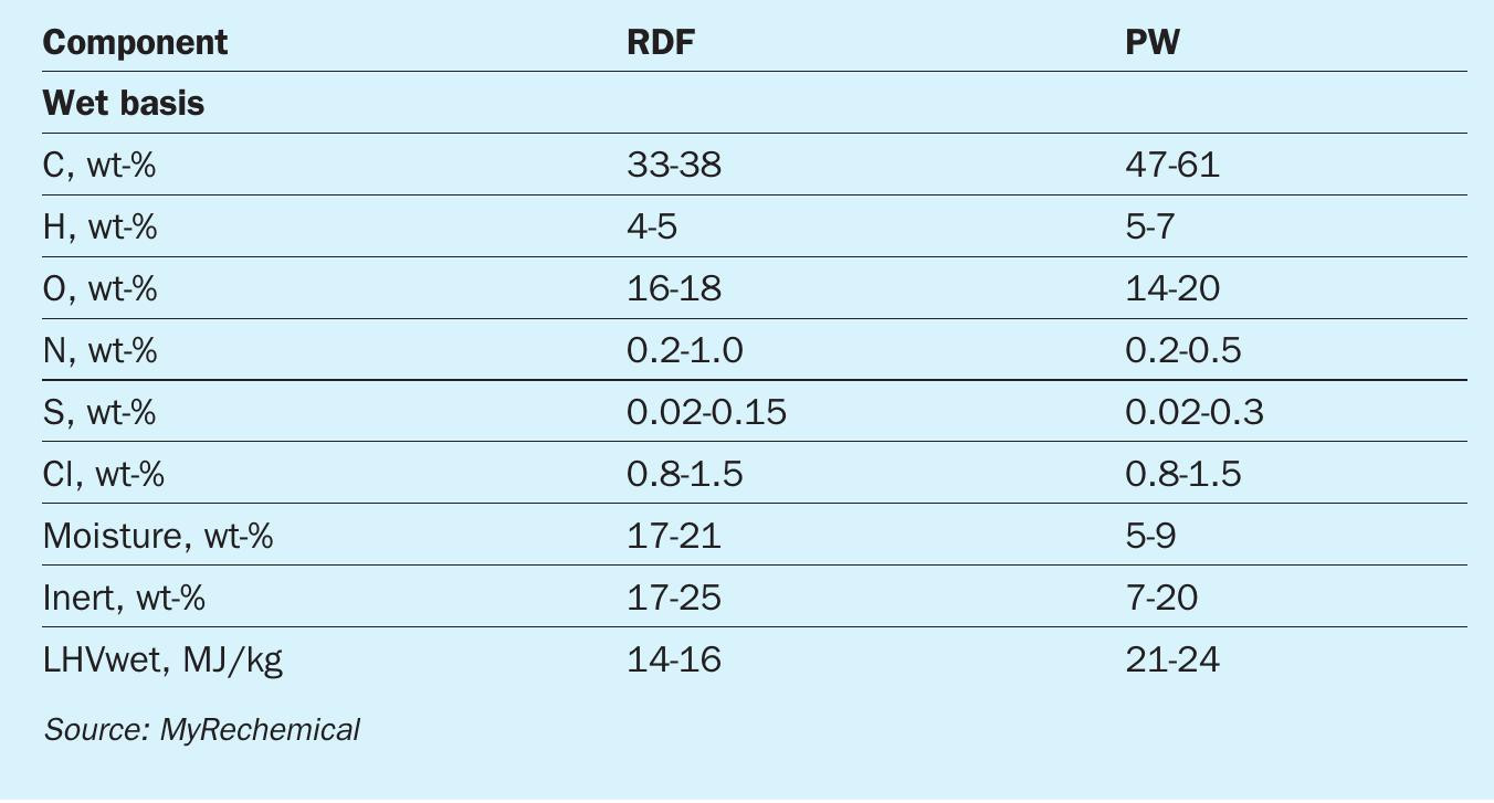
MSW, RDF and plastic waste (PW), due to the high content of carbon and hydrogen, may be considered an alternative and sustainable feedstock to be used as a substitute for conventional fossil fuels14 . Typical compositions for the types of waste mentioned above are listed in Table 1. As shown by the elementary composition, carbon content may vary in the range 30-60 wt-%, while hydrogen may vary in the range 4-7 wt-%.
Looking at the huge availability of waste, about 2 billion tonnes/annum of waste is currently produced globally and 3.4 billion tonnes is foreseen by 2050 because of the expected increase of population and GDP15 . It is therefore necessary to rethink waste as a resource rather than a problem.
Waste to chemical route Direct carbon conversion through gasification
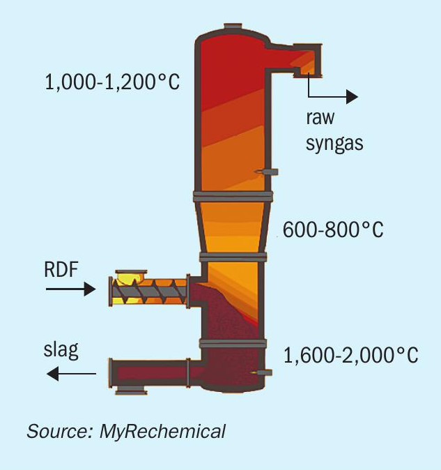
The proposed gasification technology allowing the conversion of waste into chemicals is based on a high temperature gasification process carried out under a pure oxygen environment. This is different from a thermo-valorisation technology based on a full oxidation path, and the partial oxidation reaction performed during gasification allows the conversion of feedstock into a syngas having a high content of H2 and CO. The temperature profile along the reactor is a key parameter for assuring good syngas quality. A schematic view of the gasifier reactor is shown in Fig. 1.
The gasifier reactor may be divided into three sections: the bottom melting zone (1,600°C), where exothermic reactions and the melting of inert compounds takes place; the intermediate gasification zone (600800°C), where low oxygen-content promote partial oxidation reactions; the top stabilisation zone, where a further addition of auxiliary fuel and oxygen lead to an increase of temperature (1,100°C) ensuring tar degradation and full decomposition of organic molecules as well as inhibition of pollutant compounds such as dioxins and furans.
The above-described temperature profile is controlled through multiple injection points of oxygen and auxiliary fuel along the reactor. The temperature profile assures full conversion of feedstock into a gaseous and solid product: a high value syngas rich in H2 , CO and free of char, tar, dioxins, and furans is discharged from the top of reactor and an inert vitrified material is discharged from the bottom16 . The high temperature in the melting zone allows the inert components of waste, minerals and metals to be discharged in a granulated and vitrified state, carbon free. Depending on local legislation, this material can be valorised into cement, ceramics, or used in the construction industry.
The syngas yield and relevant composition are mainly affected by the LHV value and C/O ratio: higher LHV results in higher syngas yields as well as higher content in terms of CO an H2 and lower concentration of CO2 . The syngas produced contains mainly CO, H2 , CO2 and other minor components such as volatile metals and any particles carried over with the syngas, which require a dedicated pretreatment before being fed to the synthesis section.
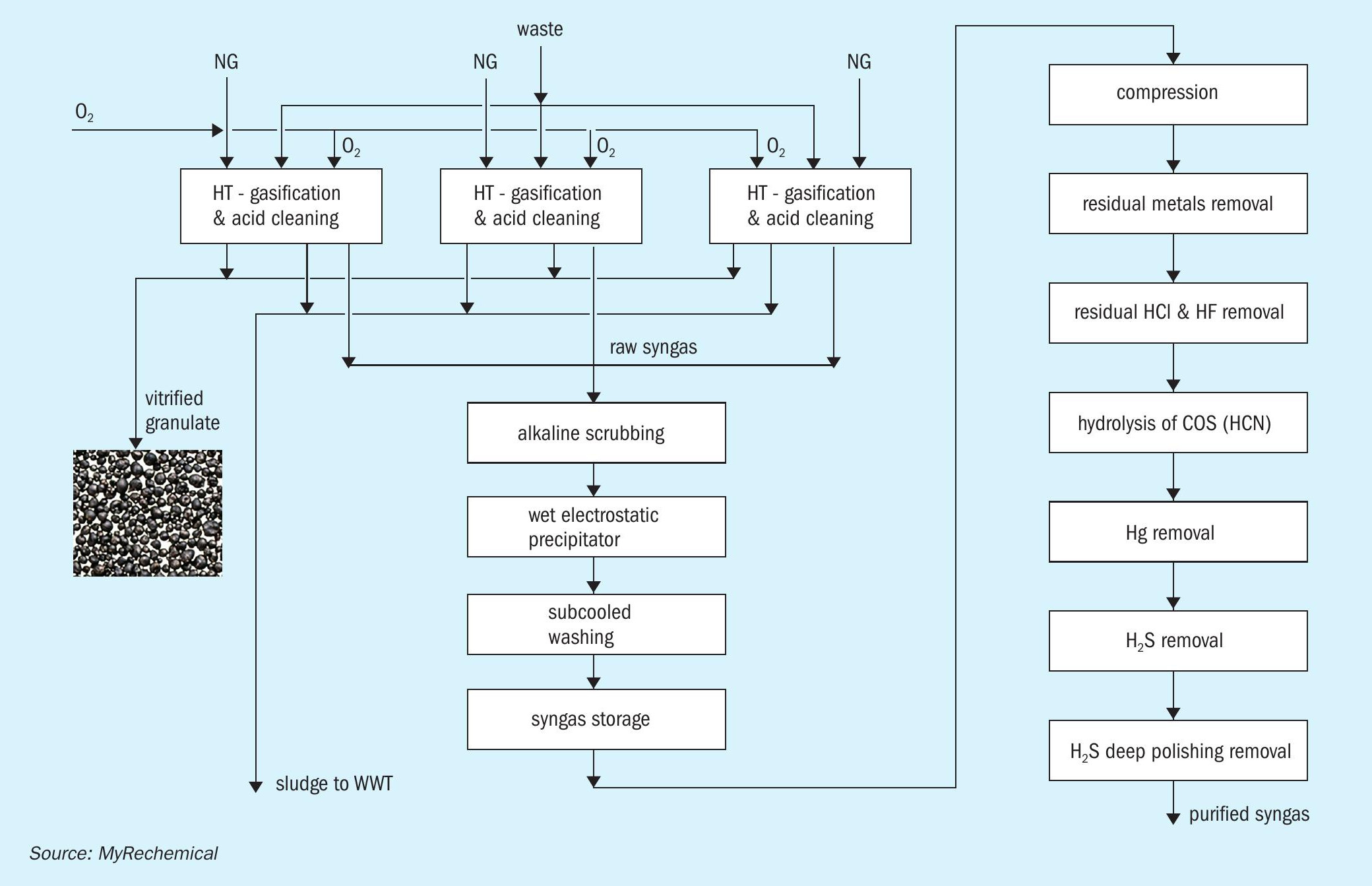
Fig. 2 shows a block diagram of the gasification section, preliminary cleaning, and syngas purification section. The hot syngas exiting the gasifier is routed to an evaporative quench, where the temperature is quickly reduced to 85-90°C by direct injection of water. Such rapid cooling, although wasting the high temperature heat contained in the syngas, freezes the chemical composition achieved at high temperature, and avoids any undesired reactions during cooling. The resulting liquid-gas mixture exiting the quench is routed to a sedimentation tank. This unit allows the collection of a concentrated sludge at the bottom of the tank which is continuously removed from the system and sent to waste water treatment, while the clairified water is directly reused in the quencher. The sedimentation tank works under low pH conditions (pH 1.5-3) to promote the migration of volatile metals into the liquid phase, mainly as chlorides. The syngas exiting the sedimentation tank is routed to an acidic column that further promotes the removal of metals.
Syngas exiting from the acidic columns of each gasification train is collected and sent to a common section comprising an alkaline scrubbing column, wet electrostatic precipitators (WESP) and subcooling washing. Water streams collected from the bottom of the washing columns are sent to the wastewater treatment unit to remove any potential pollutants.
The gasifier operates at slightly above atmospheric pressure, which results in the pressure at the end of cleaning section being a few mbar. A compression section is therefore required to route the syngas to the downstream section. To balance the flow rate and pressure fluctuations resulting from the gasifier operation, a gas holder is installed before feeding the syngas to the compression step.
The cleaned syngas resulting from the multiple scrubbing stage still contains sulphur compounds, mainly in the form of H2 S and COS, together with residual chlorine, HCN, and traces of Hg. The compressed syngas is routed to the purification section involving the following step: removal of residual dust and metals, removal of HCl, hydrolysis of the COS and HCN, H2 S removal through an oxy-reduction system and a final polishing step based on zinc oxide absorbents to reduce sulphur content down to ppb as required by the catalyst required for the downstream methanol synthesis.
The high temperature regime and the use of a waste as feedstock, requires a dedicated maintenance program aimed at preventing damage to refractory materials and avoiding excessive fouling along the quench wall and sedimentation. To mitigate reduced syngas production due to the requirement for two shutdowns per year for each gasifier for maintenance, the plant is designed with multiple gasification trains operating in parallel so that when one gasification train is down for maintenance the other two lines are kept operating at maximum capacity to ensure continuous operation with minimum turndown.
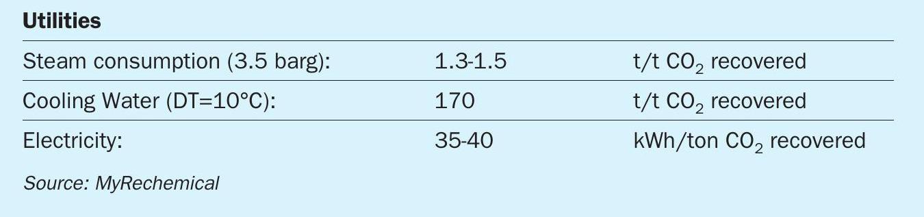
The purification procedure delivers a syngas suitable to be fed to a catalyst-based process like the synthesis of methanol. To optimise the syngas composition to produce methanol, an additional step is required to balance the ratios of H2 , CO and CO2 . This ratio is called the methanol module (MM). The MM is calculated using the following formula and has a target value of 2.1:
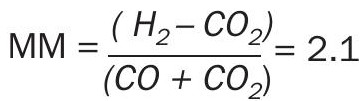
The latter is directly linked to the stoichiometry of methanol synthesis.
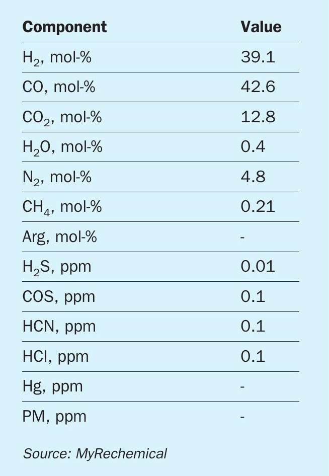
The purified syngas composition from waste gasification of a reference waste feedstock with a calorific value of 16 MJ/ kg is listed in Table 2.
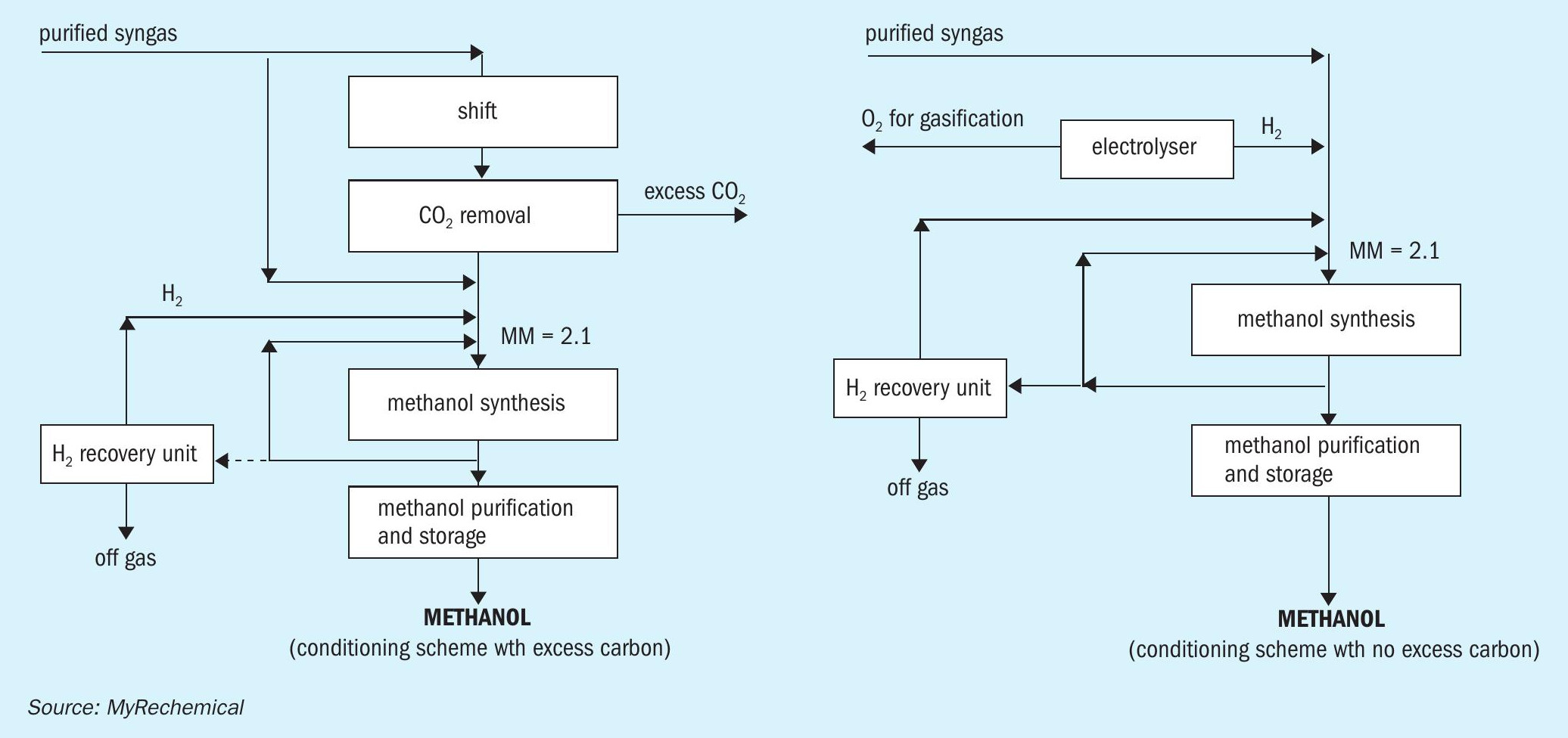
The resulting MM is in the order of 0.5, therefore the syngas requires shifting to increase the H2 content, followed by a CO2 removal step to increase the MM. This approach provides a syngas with the correct MM, with the excess carbon removed in the form of pure CO2 .
To avoid any CO2 emission in situ, an external source of hydrogen may be added to balance the excess carbon. Looking at a pressurised electrolyser as source of hydrogen, further integration may be achieved by reusing oxygen coproduced by the electrolyser to sustain the gasification reaction as shown in Fig. 3. The design based on H2 addition will allow for full utilisation of the carbon and hydrogen contained in the waste, excluding minor losses linked to off gas streams, for the replacement of the air separation unit (ASU) with the electrolyser and for the removal of the shift and CO2 removal units.
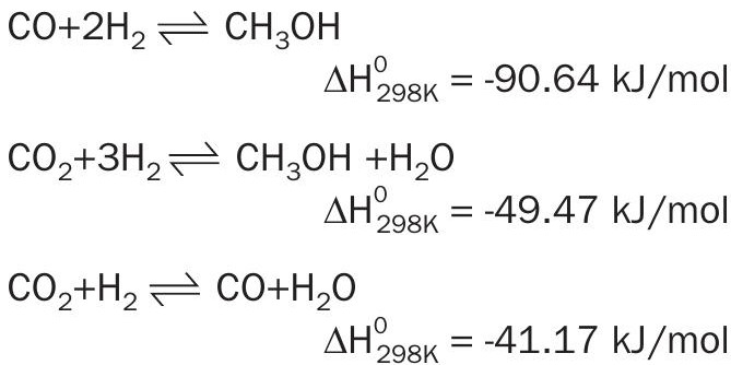
Fig. 4 shows a block diagram of a waste to methanol plant based on the gasification of approx. 192,000 t/a of waste.
The waste gasification route coupled with electrolysis designed to balance the shortage of hydrogen and to meet the oxygen requirement for gasification, allows the production of around 198,000 t/a of methanol. A supply of around 27,000 Nm3 /h of hydrogen is needed to achieve a MM equal to 2.1. Such hydrogen capacity accounts for an oxygen production that fulfils the gasification requirements as well as providing an excess of around 5.8 t/h of oxygen, which can be sold as well used in the auxiliary boiler to increase combustion efficiency. A specific electrolysis consumption in the order of 4.5 kWh/Nm3 has been considered to also take into account the power for hydrogen compression.
This route accounts for a specific CO2 production in the order of 0.136 ton CO2 /t waste with an external hydrogen requirement in the order of 1,093 Nm3 H2 /t waste. The overall power requirements are around 5.6 MWh/t methanol, where 88% of this power is utilised by the electrolyser.
Indirect carbon conversion through incineration and carbon capture
Applying the concept of CCU to waste incinerators means the conversion of captured CO2 from flue gas into methanol by direct reaction with hydrogen produced from electrolysis.
The candidate processes for post-combustion CO2 absorption must work under the following conditions:
- low CO2 partial pressure, due to near atmospheric pressure of flue gas, with CO2 concentrations in the order of 10-15 vol-%. Solvents active at low pressure are those with higher reaction energies which result in the highest regeneration energy;
- environment contains oxygen and contaminants such as NOx and SOx that can cause solvent degradation and corrosion due to the formation of degradation products;
- negligible pressure drop otherwise operating costs related to gas compression from atmospheric value would increase too much;
- flue gas is generally available at high temperature and must be cooled to minimise solvent degradation and vaporisation losses and to maintain good absorber efficiency.
An industrial technology referenced for CO2 capture from flue gas has been selected for the following comparison. It is based on a proprietary, amine-based aqueous solution of a sterically hindered amine, blended with an amine-based rate promoter to enhance the kinetics of CO2 absorption18 .
The CO2 recovery plant consists of three main sections: the flue gas quencher, the absorber for CO2 recovery and the stripper for solvent regeneration.
The flue gas is extracted by a blower from the offsite stack and fed to the flue gas water quencher, where it is cooled down to 45°C or lower. The lower flue gas temperature increases the efficiency of the exothermic CO2 absorption reaction and minimises volatilisation and thermal degradation losses of the solvent.
The quencher must be designed not only to cool the flue gas but also to remove various impurities such as SOx, NOx and dust. Depending on the flue gas composition, a pre-treating section can be requested upstream of the quencher. The flue gas in the absorber comes into direct contact with the solvent where CO2 is absorbed. To reduce amine loss the absorber column is equipped with a washing section.
The clean flue gas then moves up into the washing section of the absorber, where it is further cooled to maintain the water balance within the system and to remove vaporised solvent. The sweet flue gas is sent out to the atmosphere through a stack provided at the top of the CO2 absorber.
The CO2 -rich solvent is heated recovering heat from the hot lean solvent coming from the bottom of the regenerator. The heated rich solvent is then introduced into the upper section of the stripper, where it comes into contact with stripping steam to be converted back into lean solvent. The stripping section is powered by low pressure steam (LPS). The recovered CO2 is available at a slightly higher than atmospheric pressure thus requiring a compression to be converted into methanol.
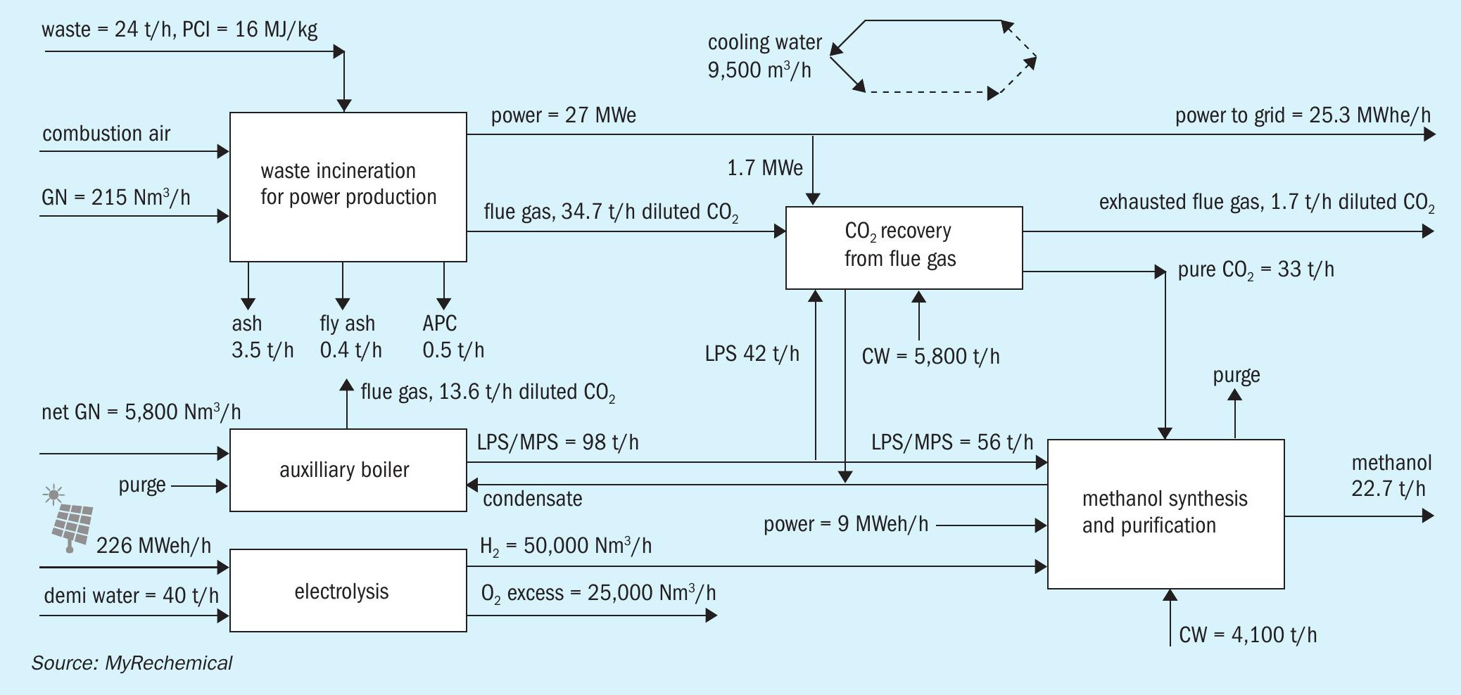
The utilities consumption of the CO2 removal package has been taken from literature as reported in Table 319 .
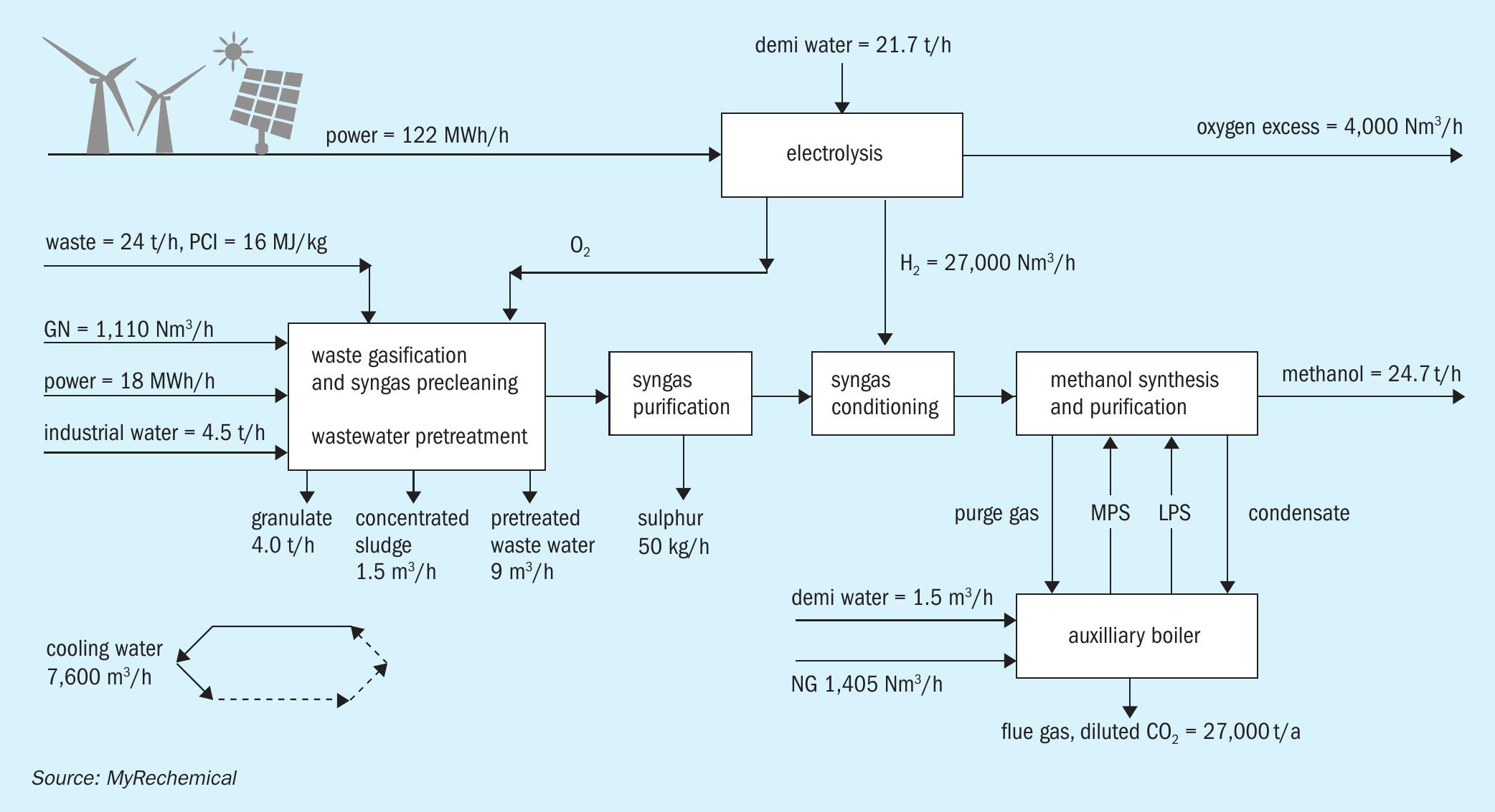
Fig. 6 is a block diagram of methanol production based on waste incinerators combined with CO2 recovery from flue gas and hydrogen supply via water electrolysis.
The incineration route integrated with CO2 capture from flue gas and electrolysis to balance the hydrogen deficit, allows the production of around 182,000 t/a of methanol. A supply of around 50,000 Nm3 /h of hydorogen is needed to achieve the stoichiometric conversion of CO2 .
Looking at the methanol section, the hydrogen requirement is higher in the incinerator than the waste-based gasification scheme due to the stoichiometry of direct CO2 conversion into methanol, which wastes more hydrogen, since one mole of water is produced for every mole of methanol in the conversion of CO2 to methanol, but that is not the case for the conversion of CO to methanol.
Such hydrogen capacity accounts for an oxygen productivity that in a conventional incinerator cannot be valorised otherwise moving from an air combustion towards an enriched air waste combustion or oxycombustion20 .
The incinerator route accounts for emissions of around 122,000 t/a, equivalent to 0.672 t CO2 /t waste with external hydrogen requirements in the order of 2,083 Nm3 H2 /t waste. Based on the assumption of an electrolysis consumption of around 4.5 kWh/Nm3 of H2 , the overall net power requirement, deducting the power directly produced from waste, results in around 9.96 MWh/t methanol.
Results and discussion
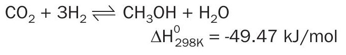
The two routes described coupling waste disposal and methanol synthesis result in different figures in terms of methanol production, utilities consumption and CO2 emission. A direct comparison is shown in Table 4.
The first section of both schemes accounts for waste disposal. Due to the different operating conditions characterising the two technologies, the co-products/by-products from gasification and incineration will be different. Thanks to the high operating conditions adopted in the bottom of the gasifier, inert components are discharged as granulate, fully vitrified and carbon free. This product, in contrast to the ash collected in the incinerator, does not require additional pretreatment, it is a non-leachable material and can be considered a co-product instead of a by-product or waste. In both schemes, gas cleaning produces a waste rich in metals: a concentrated sludge in the gasification scheme and ash resulting from the air pollution controller (APC) in the incinerator.
Assuming that all required steam is produced from a dedicated boiler instead of diverting it from steam cycle associated to the incinerator, the incinerator scheme emits overall 3.9 times more t CO2 /t methanol than the gasification-based scheme.
Extending the analysis to indirect CO2 emissions, for instance taking into account GHG emissions associated to power production, the incineration-based scheme accounts for a higher specific consumption that would imply higher emissions. Due to the high power consumption of electrolysis, the general hypothesis is to have a fully or highly decarbonised grid, otherwise any electrolysis application would dramatically alter the carbon footprint of the overall process.
Conclusion
In compliance with EC directives to promote the concept of waste as a resource, two different technologies to produce methanol from waste have been investigated and compared: a precombustion scenario, based on waste gasification and syngas conversion to methanol through electrolytic H2 addition (Scheme A) and a post combustion scenario based on waste incineration, CO2 capture from flue gas and hydrogenation to methanol through electrolytic H2 (Scheme B).
From a technical point of view the gasification-based scheme accounts for a higher yield in terms of t MeOH/t waste with a lower requirement for hydrogen from electrolysis. External hydrogen supply is 85% higher in the incinerator than in the waste-based gasification scheme due to the stoichiometry of direct CO2 conversion into methanol, requiring two moles of hydrogen compared to one for CO conversion.
The resulting methanol from both cases, according to the Renewable Energy Directive, would be recognised as a carbon recycled fuel produced from a waste feedstock. In proportion to the biogenic content of the waste, a fraction of the methanol produced may be eligible as an advanced biofuel, attracting a premium price. Moving from waste to biomass feedstock would further increase the market price of the resulting methanol.
Waste gasification provides an efficient route for the production of methanol from recycled carbon carbon, disposing of waste and with a negative carbon footprint. The integration with water electrolysis under the scenario of a fully decarbonised grid, maximises carbon conversion into methanol.
References