Sulphur 397 Nov-Dec 2021

30 November 2021
Challenges with the transition to biofuels
Considering the current shift to produce biofuels instead of conventional oil products, M. van Son of Comprimo discusses the impact that this may have on the ability to process the sour water acid gas streams produced in existing or new sour water strippers.
Sour water can be found in most industrial facilities including refineries, gas plants, power plants and chemical factories. Depending on the source of the water, the components in the sour water will be completely different.
In a sour gas processing facility, the sour water typically originates as either produced water or condensed water and may contain low levels of H2 S and CO2 as well as hydrate/corrosion inhibitors. Produced water may also contain salts. Condensed sour water is normally salt free, however may contain carry-over products from the production cycle such as amines, glycols, methanol, and other items that may have been injected into the process1 .
In an oil refining facility, the sour water can originate from desalters and processing units such as the fluid catalytic cracker (FCC) or hydrotreaters as well as amine and sulphur recovery units (SRUs) including the tail gas treatment unit (TGTU). These sour water streams distinguish themselves from gas processing facility sour water streams through their higher hydrogen sulphide (H2 S) content, the presence of large amounts of ammonia (NH3 ) and the much larger volumes that need to be processed.
The processing of these sour water streams in a sour water stripper has been well documented in literature2,3 and it is not the intent of this article to go into design details of these units or what can be done with the stripped water. The focus of this article is to discuss the impact that sour water stripping technology selection may have on the produced sour gas streams, also called sour water acid gas (SWAG), and on the options available to process these gases, considering the current shift to produce biofuels instead of conventional oil products.
Conventional sour water stripper acid gas processing
Sour water produced in a plant where no ammonia is present, such as a gas plant, typically contains very low concentrations of H2S and CO2 as neither of the gases dissolve in high concentrations in the sour water based on Henry’s law. One can expect concentrations in hundreds of ppmwt. As a result, the SWAG flow rates are very small, and in most facilities will be routed to the flare directly, where they may add a small amount of SO2 to the environmental emissions.
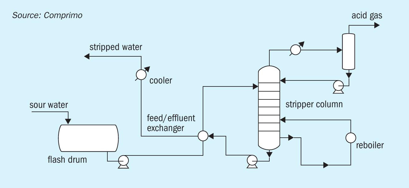
This is not the case in refineries where a large portion of the nitrogen present in the crude oil is converted to ammonia in the hydroprocessing units. Due to the rapid dissolution of ammonia in water and the formation of ammonium bisulphide in water, with equimolar amounts of ammonia and H2S, the sour water will contain large amounts of ammonia and H2S. There are usually two different methodologies for removing the H2S and ammonia from the sour water. In Fig. 1, a typical process flow scheme for a single-stage sour water stripper is provided. This configuration removes both ammonia and H2S from the water to produce a SWAG stream containing about one third H2S, one third ammonia and one third water.
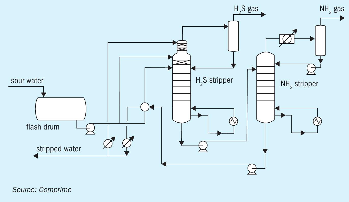
Some facilities may elect to segregate the ammonia and H2S in a two-stage sour water stripper. This results in a high purity ammonia product, which can be sold as anhydrous or aqueous ammonia and a high purity H2S product, which is processed in an SRU. Alternatively, the segregated ammonia can be destroyed in a CO boiler or other furnace. It can also be routed as a separate feed source to the SRU, which is often the destination for SWAG from a sour water stripper in a refinery environment.
Fig. 2 shows a typical configuration for a two-stage sour water stripper.
The traditional method to process SWAG in a refinery is in the thermal stage of the SRU. Due to the potential for ammonia to form salts with H2 S, CO2 and SO2 in colder sections of the SRU, it is essential to destroy the ammonia to a very low concentration (<50 ppmv). This is normally accomplished in the thermal reactor by integrating the three Ts into the design: temperature, time, and turbulence. The turbulence portion can be accomplished by installing a high intensity burner to provide good mixing of the acid gas streams and air/oxygen. A minimum temperature of 1,300°C is recommended for the destruction of ammonia. This can be done by designing the SRU with air and acid gas preheat or by installing a front-side split thermal reactor, where a portion of the amine acid gas bypasses the main burner, thereby artificially raising the air stoichiometry in the front zone to provide a higher temperature. It is recommended to limit the bypass of amine acid gas to the second zone of the thermal reactor such that the front zone remains a reducing environment as oxidising conditions can impact the integrity of the refractory. And finally, time is simply a matter of residence time in the thermal reactor. It can range anywhere from 0.8 seconds to 2 seconds depending on the ammonia concentration in the mixed acid gas or the presence of hydrogen cyanide.
The impact of biofuels on how to process sour water acid gas
With the emergence of biofuels facilities, there are new challenges with respect to sour water strippers and where and how to process the sour water stripper acid gas that is produced.
There are essentially two different methods for processing biofeedstocks in refineries.
In the first method, biofeedstocks are co-processed with conventional hydrocarbon feedstocks. This results in somewhat modified SWAG streams, without much of an impact to the downstream SRU where the SWAG is processed. Similarly, the impact on the performance of a two-stage sour water stripper to segregate ammonia and H2S is also marginal.
The second method is a standalone biofuels facility, for which the most common technology chosen nowadays is the application of hydrotreating. In this process, water is produced due to the oxygen atoms in the biomass feeding the hydrotreater, and some wash water may be required to remove any ammonia produced in the unit. As biomass is typically very low in sulphur, these sour water streams will not have the traditional equimolar ammonia and H2 S composition but will contain much higher concentrations of ammonia compared to the H2 S. These water streams may also contain a substantial amount of CO2 . In addition to the change in the sour water composition, due to the absence of sulphur components in the feed, there is usually no large amine acid gas stream associated with the unit, which traditionally would be fed with the SWAG to the SRU. As a result, in most cases these facilities will not have an SRU, which makes the question of where and how to process SWAG more important.
So, what options are there to deal with SWAG when there is very little amine acid gas available and there is still a requirement to meet certain environmental limitations for SO2 emissions? The key is how to deal with ammonia. Ammonia by itself is a very dangerous product with a TLV of 25 ppmv and cannot be released to atmosphere without destroying or removing it first.
Due to the presence of H2S, even though in smaller quantities than for conventional refineries, the treatment of the SWAG will need to be combined with the removal of the H2S before effluents can be sent to the atmosphere.
The first option discussed here is to route both SWAG and the amine acid gas that are produced together to a thermal oxidiser. Due to the presence of ammonia, the thermal oxidiser design needs to be modified to ensure that full ammonia destruction can occur, and the formation of NOx is limited. This will require special thermal oxidiser technologies like the John Zink Noxidizer or the Duiker SCO technology. The custom designed thermal oxidiser employs a staged process, whereby NH3 destruction is achieved in a reduction chamber with a high-temperature and sub-stoichiometric environment to prevent NOx formation. The gases from the reduction chamber are quenched before entering the oxidation chamber where air is injected to complete combustion. A fire tube waste heat boiler provides heat recovery and cooling of the flue gases. Due to the presence of H2 S in the SWAG, SO2 is produced and can be removed using a flue gas desulphurization technology, which in most cases uses caustic to meet the environmental targets. The absorbed SO2 is typically converted to a sulphate by introducing air in the waste stream and routed to a wastewater treatment facility.
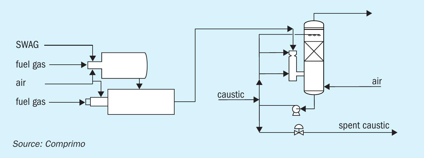
Alternative technologies such as eutectic freeze crystallisation could be considered to produce a solid product instead of a wastewater stream. Depending on the amount of sulphur present in the sour water and amine acid gas streams, the consumption of caustic in this configuration could lead to high operating costs. Fig. 3 shows the process scheme for this line up.
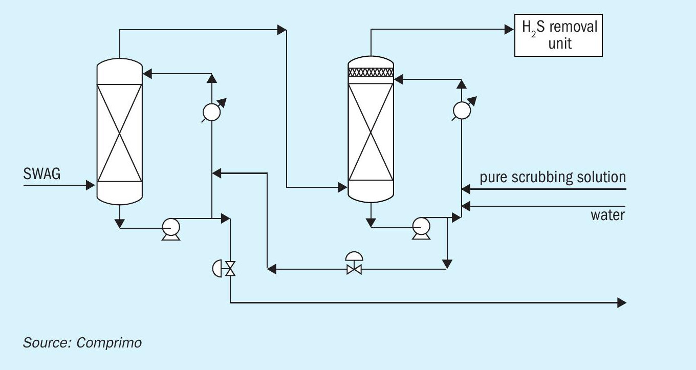
An alternative methodology for dealing with the ammonia in SWAG is to install an ammonia scrubbing system which is designed to remove ammonia before it is routed to an H2S scavenging unit.
The ammonia scrubbing system consists of a dual stage absorption system designed to remove 99.9% of the ammonia from the gas stream. In this unit, the gas is passed through two towers where the gas is contacted with an acidic scrubber solution to remove the ammonia by forming ammonium bisulphate or ammonium sulphate in solution. As the H2S in the gas phase is a weak acid, it will not be picked up by the scrubber solution, which is a strong acid. The remaining gas will contain mostly H2S and CO2 and can then be processed together with the amine acid gas (if present) in an H2S scavenging system such as LOCAT, Thiopaq or Sulfatreat. The process scheme for this solution is provided in Fig. 4.
For a biofuels facility, the primary key for processing sour water and SWAG is how to integrate the processing with the available infrastructure that may or may not be present4 . It is always the preference to use the existing sour water stripper(s) and SRU to manage the new sour water and/or reduced SWAG flow rates. In the case of a full conversion from conventional oil processing to bio feedstock, the acid gas flows may be insufficient to maintain proper operation of an existing and likely oversized SRU. In that case, the economics of the above mentioned two configurations need to be evaluated for capex, opex and integration into existing infrastructures of caustic supply as well as ability to handle the waste streams from the units.
Conclusion
With the emergence of the (co)processing of bio feedstocks in hydrotreaters, the balance of amine acid gas and sour water acid gas produced in refineries is swinging more to the SWAG side. This results in a requirement to re-evaluate how to process this SWAG.
For co-processing, the impact on the existing sulphur block is typically limited to a debottlenecking of the existing sour water system with minimal impact on the SRU.
In standalone biofuels facilities, alternative methods may need to be explored on how to handle SWAG in combination with the required SO2 emissions. Ammonia is the key component to deal with and, in the absence of an SRU thermal stage, requires alternative methods for removal with additional waste streams.
References