Nitrogen+Syngas 375 Jan-Feb 2022
31 January 2022
Better water gas shift performance
AMMONIA TECHNOLOGY AND CATALYSTS
Better water gas shift performance
The production of syngas from hydrocarbon feedstock uses a number of catalytic steps to increase efficiency and maximise conversion while minimising energy consumption. In this article we report on the latest developments in water gas shift catalysis from Johnson Matthey, Clariant and Topsoe, and shift converter design from Casale.
JOHNSON MATTHEY
Catalyst solutions delivering value in water gas shift
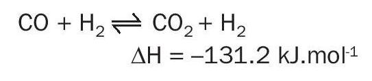
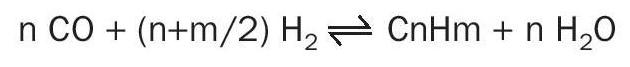
The water gas shift conversion is an important aspect to the economic operation of an ammonia plant. The reaction has a key role in the generation of hydrogen (15-20% of the hydrogen is generated via water gas shift) and also converts carbon monoxide to carbon dioxide which is more readily removed from the process:
The minimisation of the carbon monoxide slip means that there is less hydrogen consumed in the methanation of carbon oxides, and lower methane flows to the synthesis loop reducing the required purge flow. The exothermic nature of the reaction also generates heat which can be recovered into boiler feed water or steam systems.
The water gas shift process is divided between two unit operations: a high temperature shift (HTS) and a low temperature shift (LTS). Since greater equilibrium conversion of carbon monoxide is favoured at lower temperatures, a compromise is required between achievable conversion and kinetic rate. The HTS is used to do the bulk of the carbon monoxide conversion at a faster rate at higher temperatures. The LTS is then used for the final 5% of the hydrogen generation at conditions more favourable to the equilibrium.
A by-product of the water gas shift process is methanol. Methanol is undesirable since its formation consumes hydrogen that could otherwise be used for ammonia synthesis, and methanol emissions from the process can be a serious environmental concern.
High temperature shift
The first stage of the water gas process in an ammonia plant is the high temperature shift (HTS). The HTS operates at an inlet temperature of around 350°C and reduces the mole fraction of CO in the syngas to 2-4%.
High temperature shift catalysts
HTS catalysts consist of iron and chromium, promoted with copper. This formulation is selected for its thermal stability at HTS conditions. The incorporation of chromium oxide creates an intimate mix in the iron structure, which limits deactivation. This allows iron-chrome HTS catalysts, such as KATALCO™ 71-series, to operate at high temperatures without deactivation compromising the performance at lower temperatures. The KATALCO 71-series contains a very low proportion of hexavalent chrome. This is particularly important in reducing the hazards of catalyst handling. In service, the trace amounts of hexavalent chrome are converted to trivalent chrome, and formation of hexavalent chrome at shutdown can be minimised by carefully following plant shutdown procedures.
Diffusion limitations are an important factor in the catalysis of the HTS reaction. Therefore, the pore structure of the catalyst pellet is key in its performance. The structure of the KATALCO 71-series catalysts incorporate patented structural promoters that broaden the pore-size distribution which increases the activity. The benefits of the pore structure and better diffusion characteristics mean that KATALCO 71-series catalysts can be operated at lower temperatures without performance being limited by pore diffusion.
Pressure drop
Minimising the pressure drop is an important consideration in the overall process economics. The pressure drop characteristics of a catalyst is dictated by the pellet design. The design of the KATALCO 71-series pellets optimise the aspect ratio to achieve high voidage in a packed bed to deliver the best combination of pressure drop, strength and activity. Utilising patented developments in pellet design that have shown the benefits of shaped pellets, such as KATALCO 71-5F, JM can offer improved pressure drop and conversion over unshaped pellets.
The catalyst should also be able to tolerate plant upsets and retain its low pressure drop characteristics. Unplanned events that impact the HTS are likely to be wetting incidents related to boiler leaks, which can lead to increased pressure drop from the build-up of boiler solids. Robust catalysts, like the KATALCO 71-series, have good strength and open pore structure to withstand rapid cycles of wetting and drying.
Case study
A hydrogen plant in North America experienced a boiler leak of an estimated 45,000 kg/hr of water onto the catalyst for a three-month period. However, the KATALCO 71-series catalyst did not fail catastrophically as might be expected under such conditions. It continued to operate, allowing the customer to produce hydrogen until an appropriate shutdown could be planned and taken. This not only saved the plant the costs of an unplanned shutdown, but also ensured that other operations were not unduly affected. This reliability and managing of other hydrogen consumer production was valued in the millions of US dollars.
Poisoning
JM’s latest development in technology combines strong purification expertise with the design of low pressure drop systems for shift reactors to develop PURASPEC™ 2272 – a new purification tool for use in the HTS to help protect and extend downstream LTS catalyst life.
PURASPEC 2272 support media is a patented technology solution of JM to improve the water gas shift process. It utilises a low pressure drop active adsorbent support media that replaces the inert support media at the bottom of the HTS reactor. PURASPEC 2272 actively captures chloride which would otherwise poison the low temperature shift (LTS) catalyst downstream.
JM has used its expertise in purification science along with its proven STREAMLINE engineering skills to develop PURASPEC 2272 – an innovative new product which combines the functions of a low pressure drop support with that of a chloride trap.
Start-up exotherms
In some cases of high temperature shift operation exotherms can be observed when introducing steam to fresh catalyst charges. The cause of this was first identified by Johnson Matthey as the rehydration of catalyst, not, as was believed by some, the formation of hexavalent chrome. If the catalyst is held under a nitrogen purge at relatively high temperature, the surface can become dehydrated.
Then, on introduction of steam, the surface rehydrates resulting in an exotherm. Johnson Matthey can identify the conditions under which this is most likely to occur and advise a start-up procedure to avoid high temperatures. If high temperatures are seen, it again highlights the need for thermal stability in HTS catalyst, and practical experience shows that KATALCO 71-series catalysts can survive these incidents without any detrimental effects.
Initial desulphurisation
All HTS catalysts contain some residual sulphate. This is converted to H2 S during the reduction of the catalyst and has the potential to poison downstream catalysts. KATALCO 71-series catalysts are manufactured via a nitrate route whereas other catalysts may be made via sulphate routes. For catalysts manufactured via the nitrate routes, any sulphur present is not intimately bound in the pore structure of the catalyst but tends to be present at the surface. This means that the sulphur is easily reduced and removed in the fastest start-up time. For catalysts formed by a sulphate route, the sulphur in the finished catalyst is concentrated in the bulk of the structure, and the desulphurisation of these materials is slower.
Low temperature shift
Following the high temperature shift, the remaining carbon dioxide conversion is carried out in the low temperature shift (LTS). The LTS operates at an inlet temperature of around 200°C and reduces the mole fraction of CO in the syngas to 0.2-0.4%.
Low temperature shift catalysts
LTS catalysts consist of copper with zinc oxide and alumina, and other components, such as alkali metals, that can be used to alter selectivity reducing the by-product methanol make. This formulation is selected for its activity. Though it has good activity, it is not thermally stable enough to be suitable for high temperature shift conversion and is therefore only used in the LTS duty.
Catalytic activity at low temperature is an important catalyst parameter. Since the equilibrium of the water gas shift reaction dictates that higher CO conversion is achieved at lower temperatures, activity at low temperatures is key. For example, the KATALCO 83-series catalysts show activity such that the equilibrium can be achieved below 200°C and an approach to equilibrium close to zero can be achieved through the catalyst life. KATALCO 83-series catalysts have been operated at inlet temperatures as low as 190°C, and the operating temperature is often dictated by the dew point of the inlet gas rather than the catalytic activity.
Pressure drop
Pressure drop is an important parameter relating to the economics of the syngas generation train. Catalyst pellet design can improve the pressure drop of an LTS reactor, and catalyst strength throughout its lifetime is as important as the strength of the fresh pellet. The high strength of KATALCO 83-series catalysts minimises the rate of increase of pressure drop during operation, and its formulation gives high strength after reduction, steaming and any unplanned wetting events.
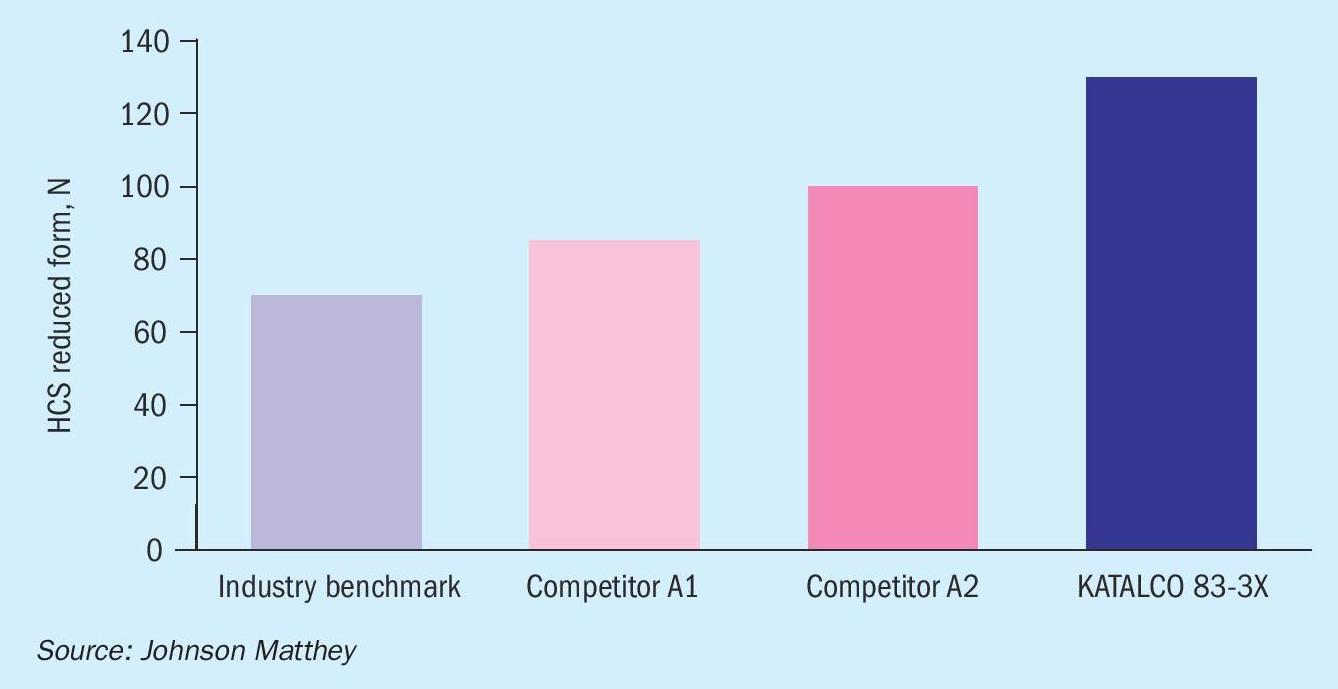
The relevant strength of any LTS catalyst is that in the reduced state since that is the state of the catalyst in service.
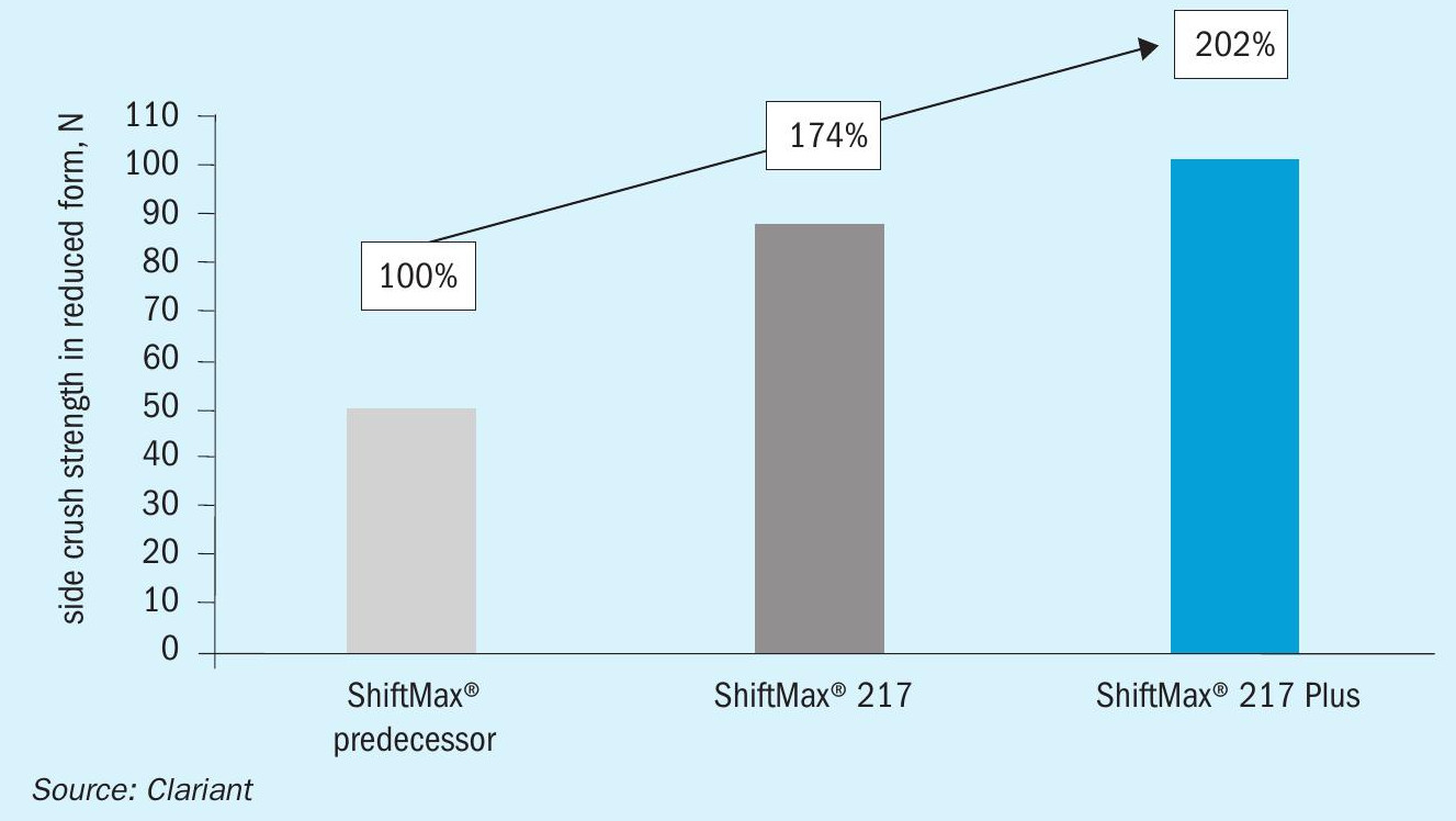
The horizontal (or side) crush strength of KATALCO LTS catalyst is compared to both the industry benchmark and recent competitive advances above in Fig. 1. This clearly shows why JM LTS is the most reliable option if an increase in pressure drop, and the losses that arise from lower rates are something that an operator wants to avoid.
Condensation on the catalyst or wetting from an upstream water quench system are the most common operational upsets in the running of an LTS. An LTS catalyst should therefore be resistant to these conditions and retain its activity and strength.
Reduced catalyst strength is important. Some low temperature shift catalysts can be too weak. KATALCO 83-3X is the optimum choice for maximum level of mechanical strength after reduction.
The outstanding mechanical stability of KATALCO 83-3 series catalysts deliver a benefit of lower pressure drop increase with time on-line and consequently a longer lifetime. There is also a much lower exposure to risk of production losses caused by pressure drop where deformation of weaker pellets can lead a resistance to flow. There are many incidents in industry where weaker LTS catalysts have caused incidents causing pressure drop losses that can be measured in one to tens of millions of dollars.
Methanol formation
Low temperature shift conditions and catalysts can result in the formation of methanol as a by-product. Methanol emissions can cause plants to exceed the consent limits under environmental legislation and can cause problems in the treatment of process condensate. In addition, the formation of methanol removes hydrogen from the process, which would reduce the capacity for ammonia synthesis. The formation of 1 tonne of methanol equates to the loss of production of 1.05 tonnes of ammonia.
To avoid the formation of methanol, LTS catalysts can incorporate alkali promoters which inhibit the methanol synthesis reaction, such as KATALCO 83-3X which includes carefully optimised levels of alkali, which retains the shift activity of the catalyst while minimising the methanol production.
Poisoning
The lifetime of the LTS catalyst is most often determined by the capacity of the catalyst to absorb sulphur and chloride poisons that are present in the process gas. The temperature of the LTS is low enough that thermal deactivation does not show as significant an effect as the poisoning. It is unavoidable that low levels of sulphur and chloride are present at the LTS, and therefore the catalyst must be designed to tolerate and accommodate them.
It is important that the LTS catalyst shows good poison retention. In this way, catalysts such as KATALCO 83-3 and KATALCO 83-3X show good self-guarding properties, retaining the poisons at the front of the bed. This means that over the lifetime the poisons accumulate in a defined poisoned section at the top of the bed, meaning that the catalyst below still demonstrates excellent activity. Throughout the life of the catalyst, the front of the poisoned section moves through the bed until there is insufficient active catalyst remaining and the bed must be changed.
It is also possible to operate with an LTS guard reactor. This is a relatively small vessel that contains a sacrificial bed of catalyst designed to collect the poisons and allow the main catalyst to operate downstream. The guard reactor can then be replaced more frequently to extend the life of the main bed. It is even more important that a guard catalyst should have a sharp front of the poisoned section to maximise the poisons capacity and avoid poisons slipping to the main bed.
Although KATALCO 83-3 series catalysts are self-guarding and have a high capacity for chloride poisons, the fact is that chloride poisons are highly mobile in an LTS if the bed is wetted. LTS beds operate with a low margin of 15-25°C against dewpoint meaning wetting can occur and result in chloride washing into the bed (Fig. 2).
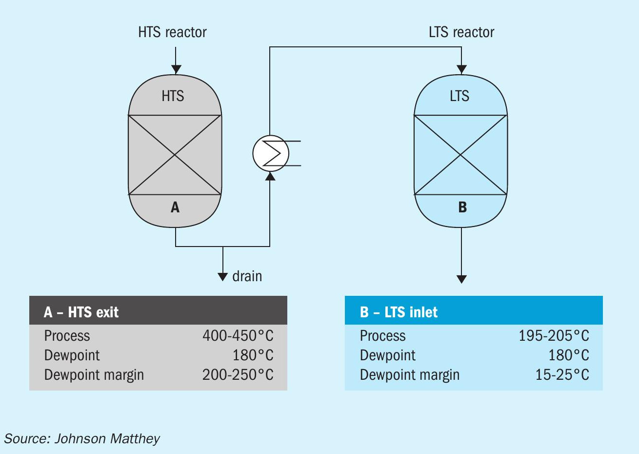
The use of PURASPEC 2272 at a location below the HTS gives several benefits including keeping chlorides from the LTS reactor, and in the event of wetting allowing chlorides to leave via a drain rather than entering the LTS.
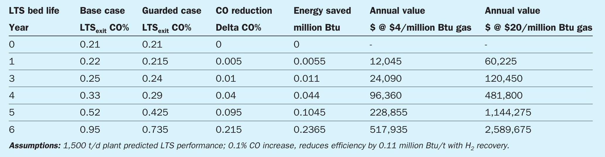
Typical results from an ammonia plant utilising PURASPEC 2272 upstream of an LTS charge are shown in Fig. 3. The reaction profile clearly shows that when using the PURASPEC 2272 solution the deactivation rate is lower than is typical.
In addition, providing chloride protection and extending the life of the catalyst, PURASPEC 2272 can provide significant protection against potentially damaging events such as unexpected transient events causing condensation. The value from this protection can be seen in the following energy saving benefits gained for a 1,500 t/d plan t for various gas costs (Table 1).
Case study
A large North American hydrogen plant experienced short catalyst lives due to chloride poisoning. During a 5-year period, it replaced a competitive LTS catalyst and its associated guard material five times. Catalyst lives averaged just one year. The plant then changed to a full bed of KATALCO 83-3X, which gave excellent performance for more than three years.
This saved the operator both replacement catalyst and unscheduled shut-down costs, estimated to be worth at least $600,000. In addition to the cost savings achieved by the plant operator, this case study also demonstrates the excellent inherent poisons resistance of KATALCO 83-3X products.
These benefits could be further enhanced by use of PURASPEC 2272, further increasing the life of the LTS and allowing flexibility on extending turnaround intervals while delivering increasing value through the lifetime through lower CO slip, and significantly lowering the risk of chloride migration in any wetting incidents.
CLARIANT
Further enhancing the benefits of LTS catalysts
The copper/zinc-based low temperature shift (LTS) catalyst is one of the highest total cost catalysts used in a typical ammonia or hydrogen plant and has a significant impact on the economics of the plant. Therefore, selecting a highly active and stable catalyst for the low temperature shift (LTS) converter is extremely important when considering the potentially harsh operating conditions under which it may have to work. With the risk of condensation (wetting), sulphur poisoning, and high temperatures (due to poor temperature control), a high-quality LTS catalyst is essential to ensure proper catalyst operation without any production loss. In addition, the catalyst needs to withstand more severe operating conditions during catalyst activation and start-up.
In an ammonia plant, a more active LTS catalyst decreases the inert concentration in the ammonia synthesis loop, reducing purge gas losses and increasing ammonia production’s energy efficiency. As a rule of thumb, 0.1% more CO converted in the LTS means approximately 1% additional ammonia, especially in plants without purge gas recovery units. Clariant’s second generation, copper-zinc based, high activity, low methanol catalyst, ShiftMax® 217, was developed to provide enhanced activity to allow higher conversion at low temperatures in addition to excellent crush strength in both the oxide and reduced state for increased robustness to enable longer catalyst life and to reduce risks of failure under upset conditions. Since its introduction in 2010, ShiftMax® 217 has been used by over 60 customers worldwide.
The following case study demonstrates the outstanding stability and robustness of ShiftMax® 217 that helped OCI Geleen overcome a water exposure incident without prematurely changing the catalyst.
Case study: OCI Geleen
Safe operations of LTS reactors under harsh conditions
OCI is a major ammonia producer operating multiple ammonia production sites around the world. OCI Geleen originates from the former DSM divisions DSM Agro and DSM Melamine. In Geleen, the Netherlands, OCI operates two ammonia plants (AFA2 and AFA3), each with a capacity of 1,550 t/d ammonia. The AFA2 plant was designed and constructed by Bechtel, commissioned in 1971, and was revamped in 1997 and 2001. The AFA3 plant was designed and built by Kellogg and is based on Kellogg’s reduced energy ammonia technology. The plant was commissioned in 1984.
Ammonia plant 3 (AFA-3) had been operating ShiftMax® 217 since 2012. In November 2015, an incident occurred that required the immediate shutdown of the plant. The focus of operations was stopping the plant as quickly and safely as possible. Therefore, the normal shut-down procedure could not be used, and the high temperature shift (HTS) and LTS reactors were taken out of operation in a non-standard manner (no circulation with nitrogen and direct depressurisation of the gas make-up section). Operations were able to minimise the ingress of oxygen, but the condensation of steam could not be prevented, resulting in severe wetting of the HTS and LTS catalysts.
During the shutdown period, condensate was drained from the inlet and outlet lines of the HTS and LTS. However, it was impossible to drain all the water because of the piping layout. This meant that any remaining water in the lines would end up going into the reactors upon restart, thereby wetting the catalysts. Wetting of the catalyst can lead to a thermal shock on the catalyst surface and condensation inside the pores, which can mechanically damage the catalyst and lead to an increased pressure drop. OCI was afraid that the Copper-Zinc-based LTS catalyst would be damaged because this catalyst type is weaker than other catalysts (e.g., HTS, Reforming) in an ammonia plant.
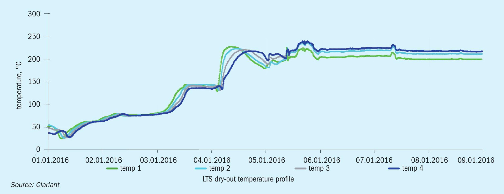
To recover the wetted HTS and LTS catalysts, Clariant advised OCI to use a slow and well-controlled dry-out procedure for both shift reactors to minimise the water vaporisation within the pores of the catalyst pellets, which can cause additional physical damage if it is too fast. The following dry-out procedure was used (Fig. 1):
l Before start-up, the inlet and outlet lines of the HTS and LTS were drained.
l Nitrogen circulation was started at low pressure to slowly remove moisture from the catalyst pores.
l The drain ports were left partially open during the nitrogen circulation until the water was no longer present.
l The catalyst beds were heated up in nitrogen circulation at a rate no greater than 30°C/hour. The inlet temperature was held when the catalyst bed temperatures no longer followed the inlet temperature. This was an indication that the dew point was reached. The inlet temperature was maintained at 10-15°C above the estimated steam dew point for approximately 12 hours to ensure slow vaporisation of the liquid from the catalyst pores.
l After this period, the heat up continued at a rate of 30°C/hour up to 225°C, at which point the reactor was ready for the normal start-up procedure. When the recommended temperature was reached, the LTS reactor was bypassed until process gas was introduced.
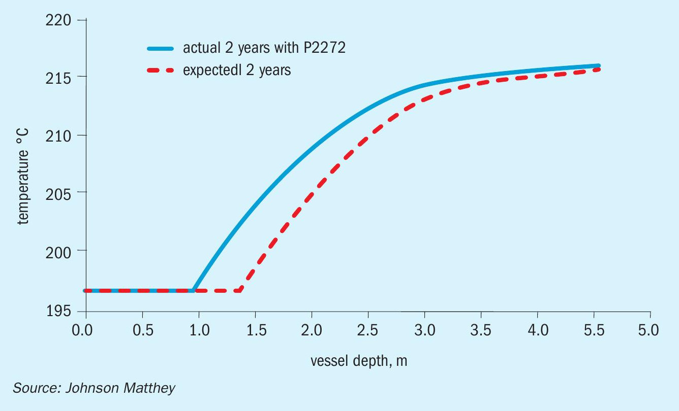
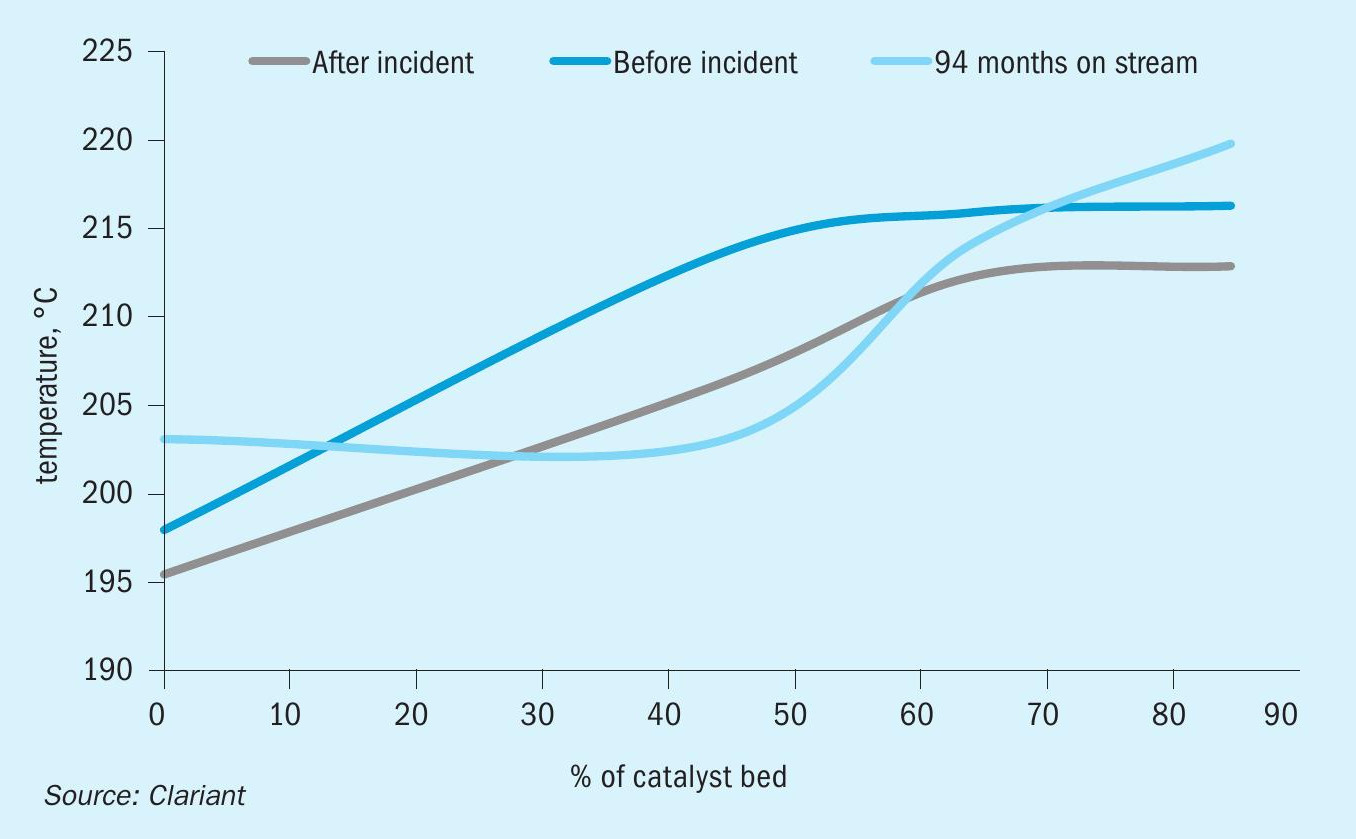
After the start-up, a catalyst performance evaluation was conducted to assess whether the wetting incident had permanently damaged the catalyst. As shown in Fig. 2, there is a slight decrease in the conversion of the LTS catalyst after the incident. Note, however, that the inlet temperature is 3°C lower after the incident. If the inlet temperature had been the same, only a minor difference would be visible.
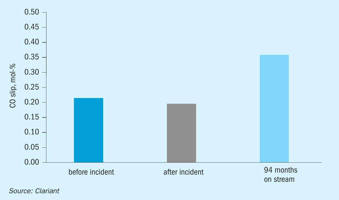
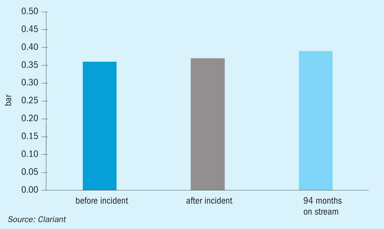
Fig. 3. shows that the CO slip was stable after the incident and still at a low level after 94 months of operation. Fig. 4 proves that the dry-out procedure was successful since there was no appreciable change in pressure drop. The comparable pressure drop demonstrated the robustness of the catalyst before and after the incident.
The lessons learned at the OCI Geleen plant show that damage to wetted LTS catalyst can be minimised by using a proper dry-out procedure before restarting production. Clariant’s LTS catalyst ShiftMax® 217 has proven to be robust, even in a severe wetting incident. Hence no early changeout was necessary.
This incident demonstrates that combining a robust and highly active catalyst, such as ShiftMax® 217, and close cooperation between operating plant and catalyst vendor leads to safe plant operation and significant savings due to avoided downtime and avoided catalyst replacement costs.
New ShiftMax® 217 Plus LTS catalyst
Clariant has not stopped at the highly active and robust ShiftMax® 217 but developed ShiftMax® 217 Plus, the next generation of LTS catalyst for ultra-low methanol formation and outstanding physical strength. It utilises the proven chemical composition of ShiftMax® 217 and exhibits the same high activity but with further improved selectivity and mechanical strength.
Due to the introduction of an optimised production process, ShiftMax® 217 Plus exhibits a more homogenous distribution of the active metals and promoters within the catalyst matrix. The catalyst selectivity is enhanced by the optimised promoter concentration and distribution.
Lower by-product methanol formation
By-product methanol formation consumes hydrogen leading to H2 yield losses and/or lower energy efficiency and technological and environmental problems (VOC/COD emissions).
CO2 + 3H2 = CH3 OH + H2 O + heat
Excessive methanol make will not only contaminate CO2 and process condensate, but it also causes loss of ammonia production. As a rule of thumb, every tonne of methanol produced in the LTS results in 1.1 tonnes of ammonia loss. Methanol formation is driven by gas composition, operating conditions (similar to methanol synthesis), and catalyst type. Therefore, the methanol formation rate may be reduced by increasing the steam to gas ratio, using low-methanol catalysts, and improving the aging behaviour of the catalyst.
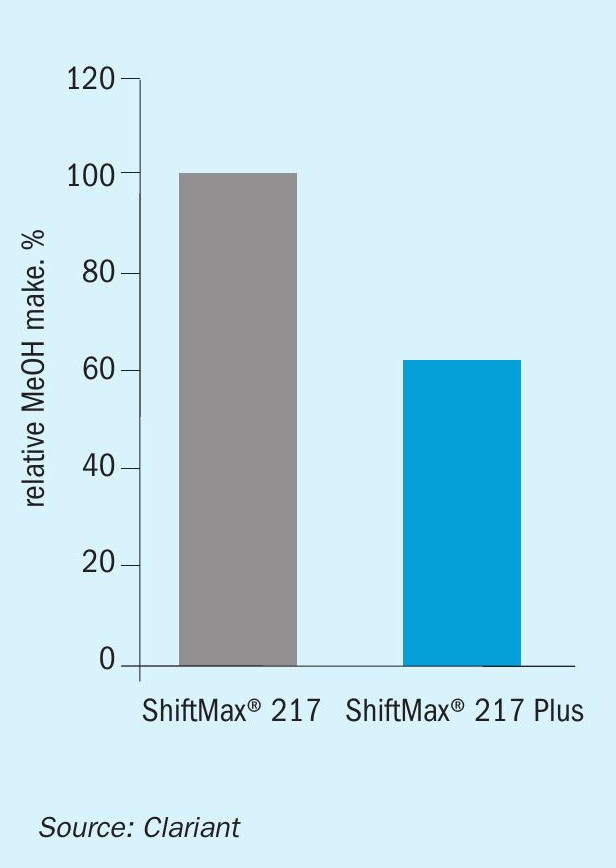
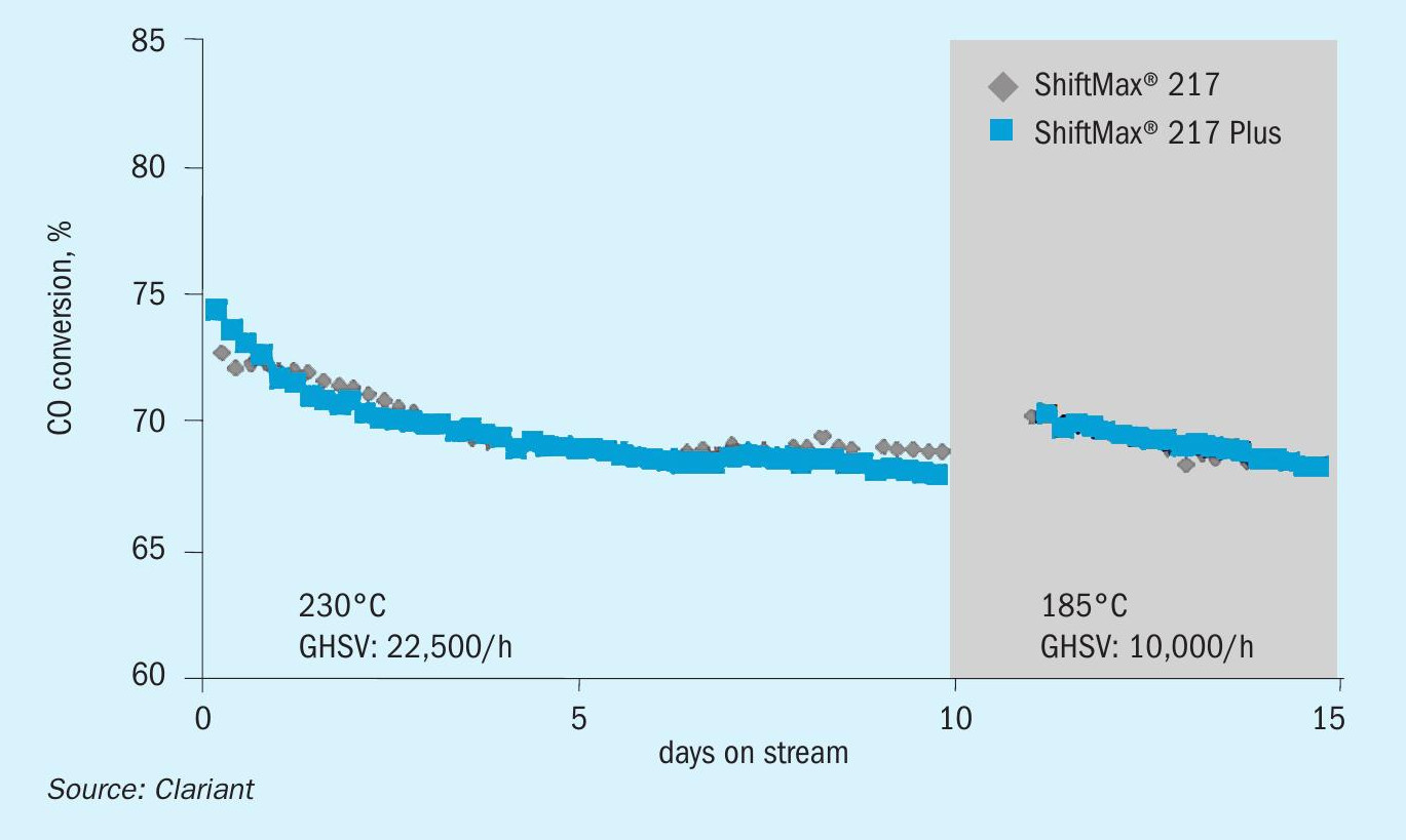
In laboratory tests, ShiftMax® 217 Plus demonstrated ultra-low methanol formation without compromise on activity. Compared to the commercially proven version ShiftMax® 217, the new catalyst provided the same high level of CO conversion but formed 40% less methanol (Figs. 5, 7).
The ultra-low methanol make provides several benefits:
l leads to increased ammonia production and/or energy savings;
l leads to cost savings in the downstream treatment system, e.g., condensate system, solvent regeneration, etc.;
l helps to reduce VOC/COD emissions;
l mitigates the limitation on the capacity increase due to VOC/COD emissions.
Mechanical stability
Apart from the strongly reduced MeOH formation, ShiftMax® 217 Plus has higher mechanical strength, as shown in the significantly improved side crush strength (SCS) after reduction (Fig 6). This will result in a lower pressure drop increase with time on stream and consequently to a longer catalyst lifetime.
Conclusion
The convincing case study at OCI Geleen and the successful launch of ShiftMax® 217 Plus impressively point out that Clariant continuously evaluates product performance from customer feedback and combines it with intensive R&D efforts. In this manner, Clariant continues to innovate and further enhance the benefits of its catalysts to bring additional value to customers.
TOPSOE
New formulation for HTS catalysts is industrially proven
The fundamental iron-chromium composition of today’s conventional HTS catalyst was first discovered in 1914 by Bosch and Wild and has been in commercial use since that time. The iron oxide in the catalyst is commonly produced as hematite (α-Fe2 O3 ) and reduced in situ to generate the catalytically active phase of magnetite (Fe3 O4 ). Chromium oxide is added to the catalyst as a textural promoter because unpromoted magnetite easily sinters under HTS conditions, leading to reduced surface area and significant loss of activity. In moderate amounts, chromium oxide also functions as a chemical promoter, enhancing the intrinsic catalytic activity of iron oxide. Another valuable promoter, copper, was discovered in the 1980s, as demand began increasing for more energy-efficient plants. The addition of copper was found to increase catalyst activity and selectivity, which reduced by-product formation from Fischer-Tropsch reactions at lower S/C (steam to carbon) ratios.
Challenges of conventional Fe-based HTS catalysts
In the last few decades, a large number of research efforts in HTS catalysis has been motivated by the drawbacks of modern iron-based catalysts, for example, the presence of toxic hexavalent chromium and over-reduction of iron oxides at low S/ DG (steam to dry gas) ratios.
Chromium promoters in fresh Fe-Cr ‐Cu catalysts are often present as surface Cr(VI) species (i.e. in CrO3 ) that reduce to Cr(III) (i.e. Cr2 O3 ) under HTS conditions. Cr(VI) is a Category 1 carcinogen and is water soluble, meaning that it can be washed out of the catalyst into the condensate stream during start-ups, resulting in an environmental clean-up issue and resulting in lower chromium content in the catalyst and consequently less stability. As Cr(VI) is also very exothermic during reduction, this can lead to very high catalyst temperatures that, in worst case scenarios, may exceed the design temperature of the reactor. To avoid potential damage to the catalyst and the reactor, extra procedures must be performed during start-up, adding to plant downtime. Accidental leaks of the volatile Cr(VI) are a risk to personnel safety and to the environment, and such incidents can be very costly for a plant due to unplanned downtimes and long-term liability issues. Catalysts containing Cr(VI) must be compliant with the European REACH regulations, and spent catalysts must be disposed of in accordance with toxic waste regulations.
The risk of over-reduction of iron oxides in conventional HTS catalysts is also a major issue because of the limitation it puts on S/DG and therefore S/C ratios. At S/C ratios lower than approximately 2.8 the iron in conventional HTS catalysts will be reduced to lower oxides, metallic iron species or iron carbides:

Iron carbides in turn are very effective catalysts for the highly exothermic methanation reaction and Fischer-Tropsch reactions:
This production of higher hydrocarbon by-products consumes hydrogen that would otherwise be used for valuable hydrogen or ammonia production and results in physical damage to catalyst pellets. Loss of catalyst mechanical strength in turn leads to increases in pressure drop as well as premature catalyst unloading and replacement. The addition of copper promoters is effective in inhibiting the Fischer Tropsch reaction at low S/C ratios, but it does not eliminate it.
To avoid the negative consequences of by-product formation, it is important to maintain a minimum S/C ratio not only during normal operation but also during reduction and activation. Fe-Cr-Cu catalysts require special considerations during start-up to ensure that they are properly reduced not only to avoid iron over-reduction but also to avoid damaging consequences of the exothermic reduction of Cr(VI) to Cr(III).
A new formulation for HTS catalysts
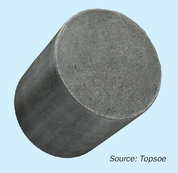
Although much work has been done in developing improved Fe-Cr-Cu catalysts that address the above challenges, the basic formulation of commercially viable high temperature shift catalyst remained unchanged until 2016 when Topsoe introduced SK-501 Flex™ , a new HTS catalyst based on zinc oxide and zinc aluminium spinel and containing no iron or chromium (Fig. 1). This fundamental composition has long been known to have some degree of activity for the WGS reaction. Topsoe’s contribution is the addition of certain promoters and an effective preparation method that give the new catalyst a high level of activity, even after extended periods of operation. Furthermore, the notable absence of chromium makes this new formulation safer to handle and more environmentally friendly.
The performance of SK-501 Flex™ has been optimised as a result of meticulous, systematic studies of the catalyst parameters by the company’s R&D division. The zinc aluminium spinel, coupled with the right amount of promoters, manages stability while maintaining a high level of poison resistance.
Benefits of SK-501 Flex™
The most significant benefits of SK-501 Flex™ compared to conventional Fe-Cr-Cu catalysts are:
l extended operational flexibility;
l higher production rates;
l improved energy efficiency;
l exceptional activity and stability;
l minimum by-product formation;
l no risk to personnel health and safety;
l low environmental impact;
l hassle-free start-up.
The innovative composition of SK-501 Flex™ offers ammonia and syngas producers the possibility to operate the plant at S/C ratios previously unattainable with commercial catalysts, to achieve greater improvements in capacity increase.
Additionally, low S/C ratios make it possible to significantly reduce energy costs. At a modern ammonia plant, operation with SK-501 Flex™ could bring energy consumption 1.6% closer to the theoretical minimum (see Fig. 2). Such energy savings would be achieved from reduced steam input and from an overall reduction in natural gas consumption.
The exceptional activity of SK-501 Flex™ also contributes to better energy efficiency. The activity allows for lower inlet temperatures, keeping conversion high even at lower plant S/C ratios (Fig. 3). This translates into lower pressure drop over the reactor and less energy consumption by the compressors.
With SK-501 Flex™ , there is no longer a risk of over-reduction at low S/DG ratios. There is no formation of the higher hydrocarbons, acids or esters catalysed by over-reduced iron oxide, even at extremely low S/C ratios). This eliminates the consumption of valuable hydrogen and the contamination of process condensate due to these byproducts.
A small amount of methanol is formed over any type of HTS catalyst due to the equilibrium reaction for methanol from the reaction of CO2 and H2 .
Like Topsoe’s ultra-low Cr(VI) SK-201-2 catalyst, start-up is easy and hassle-free with the chromium-free SK-501 Flex™ . There is no need for extra start-up procedures that are normally needed when hexavalent chromium is present in the catalyst. With SK-501 Flex™ , activation is fast and takes place in connection with the start-up of the reforming section, saving producers costly downtime.
The complete absence of chromium also allows plants to avoid the potential risk that chromium poses to personnel health and safety and to the environment during product handling and operation. By avoiding this risk, plants reduce the possibility of unplanned and costly downtimes as well as long-term liability issues.
Reactor loading schemes with SK-501 Flex™
There are multiple loading scheme possibilities for SK-501 Flex™ . It can be loaded alone in the HTS vessel or as part of a split loading, where SK-501 Flex™ is loaded on top of a conventional iron-based HTS catalyst such as Topsoe’s SK-201-2. Split loadings can be recommended in the case of moderate decreases in S/C ratio, for which the gas has the highest potential for causing overreduction of the Fe-Cr-Cu catalyst in the top of the vessel.
A top layer of the TK-20 guard catalyst above SK-501 Flex™ is an additional loading option and is recommended for plants that typically experience impurities in the process gas or in the quench water/ steam. These impurities, such as silica, potassium and sodium compounds, can also enter as a result of boiler leakages upstream of the HTS reactor. The HTS catalyst is particularly vulnerable because it is often the first in the train of catalysts operating at temperatures at which condensation of volatile contaminants can occur. The consequences include serious pressure drop issues and uneven flow distribution. Composed of inert magnesium aluminate spinel, TK-20 provides high porosity and high bed void fraction, which effectively trap and distribute foreign material over a relatively large volume.
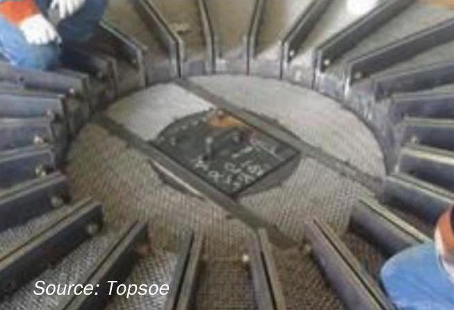
Further pressure drop reduction is possible by replacing most of the aluminum support balls with a catalyst support grid in the bottom of the HTS reactor. The support grid consists of a modified outlet collector, outlet brackets, outlet connector rods, skirt section and a mesh grid section, all of which float in the bottom of the vessel. Fig. 4 shows side and top views of the support grid.
Operating data from industry
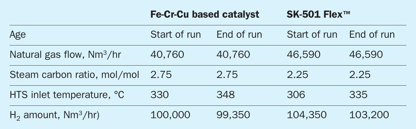
Operating data for the new catalyst in a European hydrogen plant are shown in Fig. 5. It was installed to help the plant achieve higher efficiency by decreasing the S/C ratio to 2.5. With the previous catalyst, the minimum S/C ratio was 2.8. During more than 60 months the catalyst demonstrated its performance with low and stable pressure drops and activity levels that exceed the expected activity of many standard HTS catalysts.
Increased production rates
The higher activity will give a higher conversion in the HTS reactor throughout the catalyst lifetime. In a standard 100,000 Nm3 /hr hydrogen plant, the extra production is in the order of 0.3-0.5% just by changing catalyst. Even higher production gains can be achieved by lowering the S/C ratio. With the possibility of operating the plant at S/C ratios previously unattainable with commercial catalysts, producers can achieve improvements in capacity increase. For example, a decrease in S/C from 2.75 to 2.25 can result in 3-5% more hydrogen produced, using the above plant as a basis and simply reducing the steam flow to the plant and increasing the flow of hydrocarbon feedstock. Table 1 shows the comparison.
On top of the production increase, other benefits such as reduced natural gas fuel consumption in the steam reformer, energy requirement in the cooling train between the HTS and PSA unit, and an increased steam export can be achieved.
The use of Topsoe’s catalyst can be an inexpensive revamp option for a plant looking to increase its production rate; only requiring a catalyst replacement as opposed to extensive capital expenditures.
Applications of SK-501 Flex™
The SK-501 Flex™ catalyst can be used in the HTS reactor at any modern ammonia, syngas or hydrogen plant. The catalyst can be installed as a direct replacement of a conventional HTS catalyst and can play a vital role in the case of revamps as well as new plants. When reducing the plant S/C ratio, the effects of reduced steam input and increased feed gas flow must be considered carefully, and a detailed assessment of the plant must be made.
With the removal of the S/DG limitation, other factors that may determine the operating S/C ratio include feed gas composition and its possible fluctuations, steam requirements in the CO2 removal section, distribution of duty between primary and secondary reformers, operating pressure, reformer firing rates, and the possibility of metal dusting in the waste heat boiler.
The advantage of SK-501 Flex™ is the opportunity to reduce steam addition and therefore benefit from significant energy savings. One example of another application is the gasification of carbon-based fuel to syngas, a process that is made more efficient by utilising the WGS reaction. The catalyst can also be used in a reverse WGS process. In such cases, it is not only the catalyst’s ability to operate at low S/DG ratios that make it a good candidate but also its impressive thermal stability.
Summary
Topsoe’s latest development in HTS catalysis is industrially proven. With this new catalyst, producers are able to operate at S/C ratios that until now were unattainable, giving the producers more plant flexibility and the subsequent benefits of reduced energy consumption and increased production rates. Additional benefits are a result of its iron and chromium-free formulation and include improved personnel safety, reduced environmental impact, hassle-free start-up, and minimum by-product formation. The possible applications in which the catalyst can be used are numerous, ranging from hydrogen plants, ammonia, and syngas plants to cutting-edge projects such as biogas production, CO2 capture and storage, and modern fuel cell power generation.
CASALE
Optimising CO conversion with the Casale isothermal shift converter
Casale’s axial-radial catalyst bed technology is a well proven and established technology used in both HT and LT adiabatic shift converters. Since 1995, with the first reference in China, the axial-radial design has been adopted by Casale in more than 50 shift converters. In addition to the adiabatic shift converter, Casale also offers an isothermal shift converter design, representing the latest development in Casale reactor technology for new grass roots ammonia or hydrogen plants.
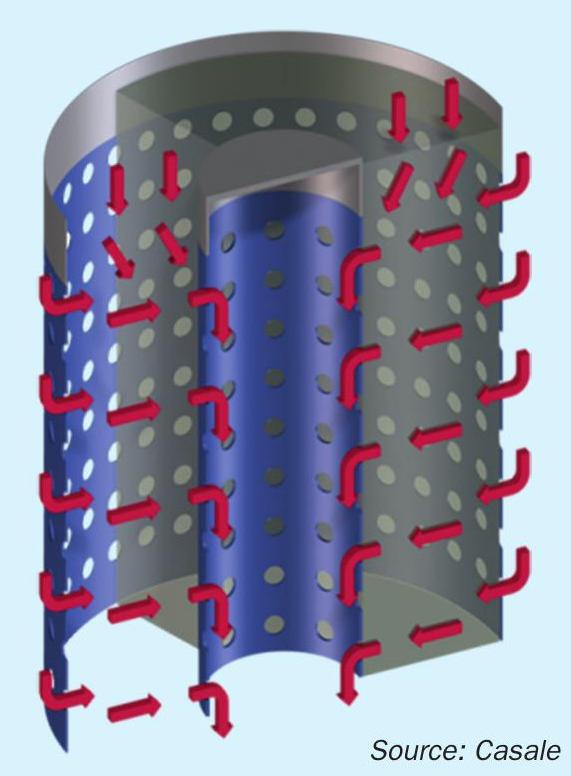
Casale axial-radial converter design
Fig. 1 is a schematic view of the gas flow path in an axial-radial converter. As shown, most of the process gas passes through the catalyst bed in a radial direction, resulting in a lower pressure drop than in the case of pure axial flow since the gas velocity is smaller. A typical value for the pressure drop through the catalyst bed is 0.3 bar.
The balance of the reacting gas flows downwards through the top layer of catalyst in an axial direction, thus eliminating the need for a top cover of the catalyst bed. This feature allows both simple construction of the converter internals and complete catalyst volume utilisation (even in the top part).
Furthermore, most of the pressure drop is concentrated at the inlet and outlet of the catalyst bed, where perforated walls control the gas flow through the bed. This configuration allows an optimal gas distribution, independent of possible non-uniform catalyst packing inside the bed due to poor loading or other reasons.
Fig. 2 is a schematic of the Casale axial-radial adiabatic shift converter. The success of the axial-radial design can be attributed to its numerous advantages:
No possibility of channelling: The gas distribution in the catalyst bed is independent of the catalyst loading, age and condition, since it is controlled by the perforated walls and not by the catalyst itself. This ensures perfect distribution and full utilisation of the bed in all operating conditions and loads, and independent of catalyst poor distribution, ensuring a longer life for the same catalyst volume.
Low pressure drop: The lower gas velocity of the axial-radial flow in the catalyst, compared with the axial bed, ensures a low pressure drop even in case of unexpected events, such as carryover of powder or water droplets.
Use of small-size catalyst: The axial-radial converter allows using smaller size catalyst with no detrimental effects on pressure drop. It is well known that in any pore-diffusion limited reaction such as the CO-shift conversion, the apparent catalyst activity is inversely proportional to the pellet dimensions since only the outer portion of the pellet tends to be used. Smaller size catalyst is more active than larger size catalyst thanks to its higher surface area per unit of volume, and this higher activity facilitates a longer catalyst life for the same loaded volume.
Protection of catalyst from water droplets: In many plants, the pressure drop of industrial axial shift converters builds up during the operating life, because of water droplets carried over by the incoming gas, which tend to form a caked layer at the top of the bed.
When the pressure drop exceeds the maximum admissible value the top layer of catalyst is skimmed off or, in the worst case, the whole catalyst charge has to be replaced.
The axial-radial bed design, for fluid dynamic reasons, concentrates the water droplets contained in the gas feed on the top layer of catalyst (axial part of the axial-radial bed). The caked layer, which may eventually form, will simply shift the incoming gas toward the radial inlet distributor, thus minimising the effect on the total pressure drop. Therefore, even in the event of a severe leakage of water from an upstream boiler, the shift catalyst and internals will be protected from any damage.
With axial-radial internals, the total bed pressure drop therefore remains constant with time because the catalyst pressure drop is negligible during the whole catalyst lifetime and all the pressure drop is concentrated in the nozzles and in the perforated walls, that do not change their characteristics with the time.
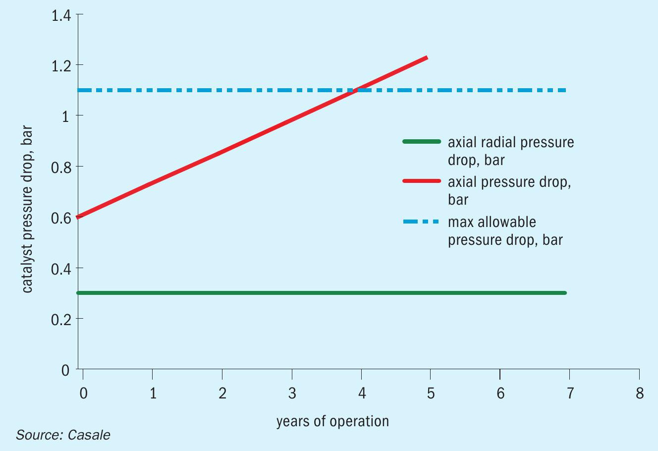
Fig. 3 shows a typical pressure drop trend for shift converters. It is apparent that a low and constant pressure drop, as achieved with axial-radial internals, can increase the operating life of the catalyst, compared with the axial internals if affected by water impingement.
Casale isothermal converter design
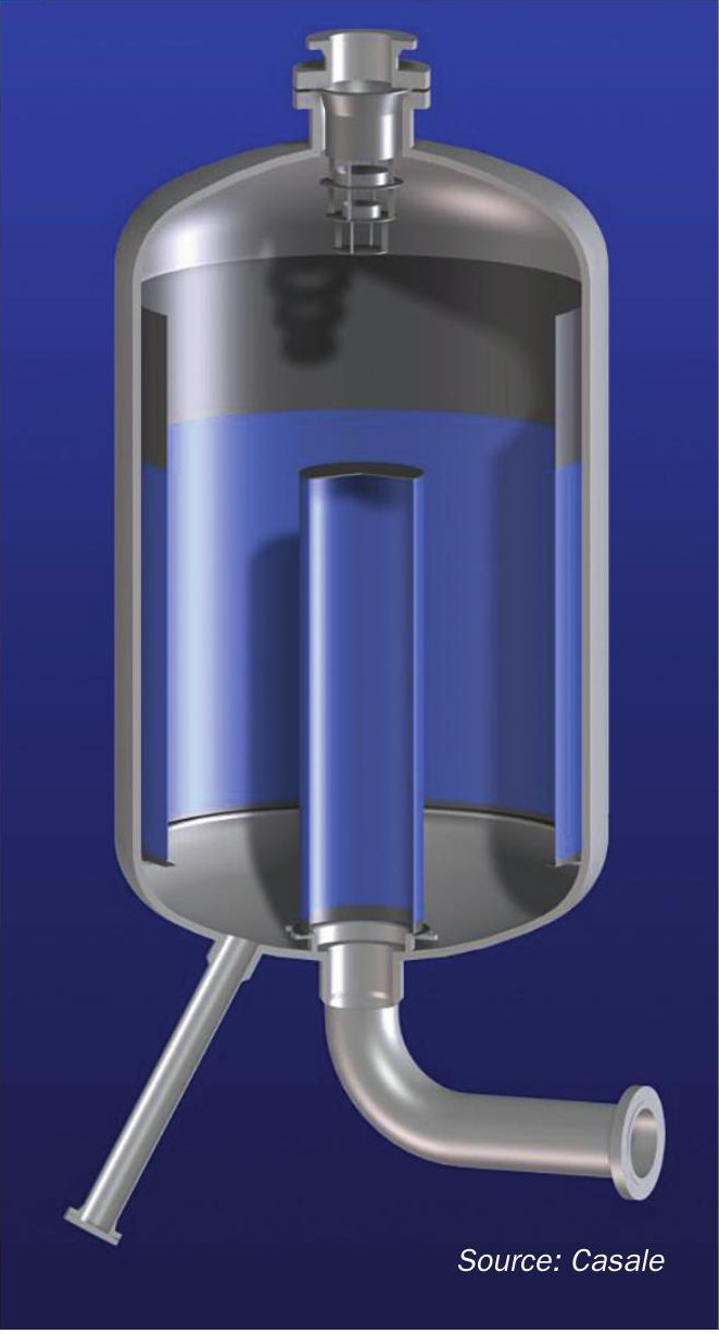
Casale’s latest shift converter design, the isothermal shift converter, allows isothermal operation of the reactor by heat exchange with a coolant flowing in a panel type heat exchanger dipped vertically into the catalyst mass. Fig. 4 shows a 3D rendering of the isothermal shift converter.
Compared to an adiabatic converter, a lower temperature is reached at the bed outlet of the isothermal converter with the same catalyst volume and process gas inlet temperature, thus performing a higher conversion.
The high efficiency of the isothermal design enables lower synthesis gas consumption (to attain the same production), or higher production (with the same synthesis gas). Moreover, the heat removed by the exchange plates can be recovered (by heating boiler feed water or generating steam) thus reducing the amount of equipment to be installed.
Principles of isothermal design
The isothermal reactor mainly consists of a catalytic bed with a plate-exchanger dipped into the catalytic mass for direct heat removal. The continuous catalytic layer is cooled by means of the exchange plates vertically immersed inside the catalytic mass. The catalytic bed is supported on a layer of alumina balls of different size. The reaction heat of the isothermal stage is removed by heat exchange with boiler feed water inside the plates.
The heat exchange rate is carefully evaluated to obtain the best possible reaction path inside the catalyst. In view of this target, the design of the reactor internals requires particular care and knowledge.
Moreover, the control of the reactor is designed to allow stable and efficient operation under all possible operating conditions. In particular, the parameters to be controlled are the inlet temperature to the catalytic bed and the BFW temperature within the plates. The latter can be controlled through partial or complete bypass of the plates or by steam generation pressure (in case of a steam rising arrangement).
High performance
The performance of the isothermal axial-radial design, based on the innovative concepts explained in the previous paragraphs, are superior to the adiabatic design and can be summarised as follows:
Efficiency: The CO conversion performed in the isothermal converter is higher, thus making it possible to reduce the make-up gas consumption for a given hydrogen production.
Pressure drop: The heat exchanger plates installed in the converter allow a more compact plant flowsheet, resulting, in particular, in a more compact heat recovery train in the same plant section. As a result, the pressure drop on the gas side is lower.
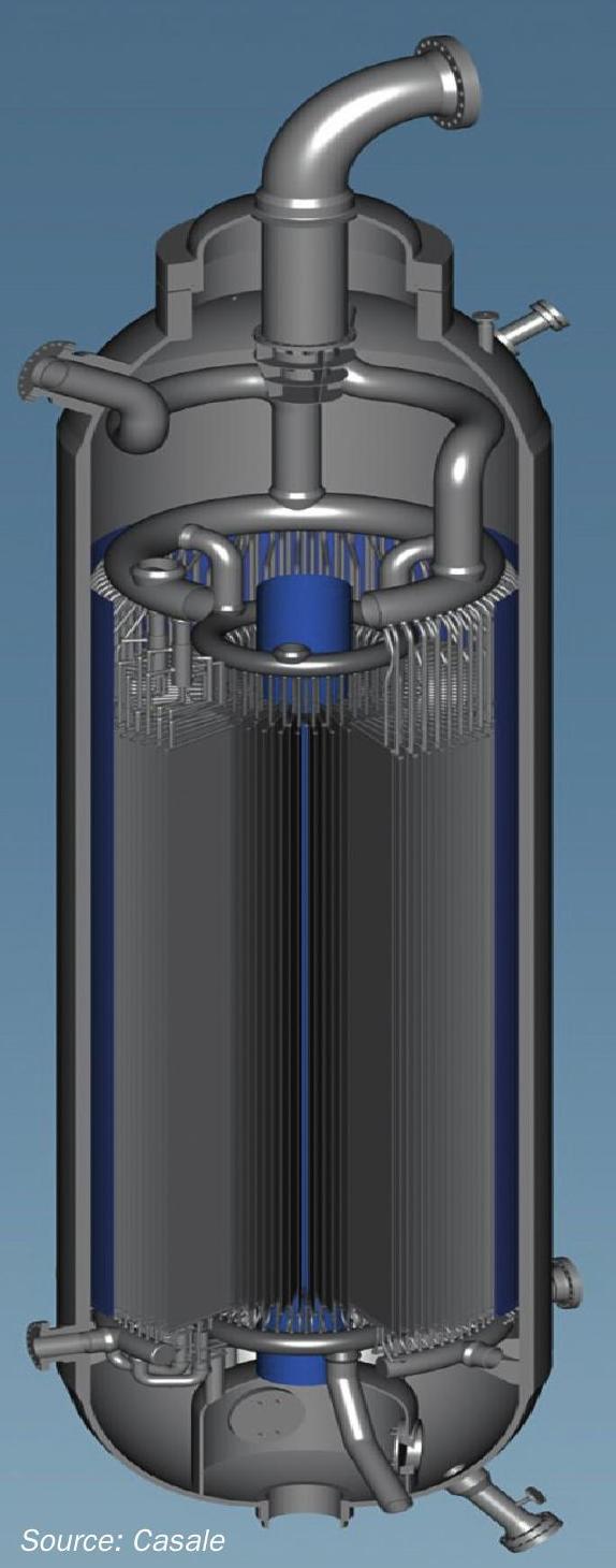
Mechanical features
Conscious of the important role that reliability plays in the operation of converters, Casale has developed the isothermal design up to successful industrial implementation with the most careful attention to every mechanical detail.
A summary of the most significant features in the isothermal design are:
l the vessel is filled with one continuous layer of catalyst;
l the heat removal inside the catalyst is performed by the heat exchange plates;
l the heat exchange elements are suitably designed for this specific service, considering the critical environment where they will operate (catalyst actions, thermal expansion, mechanical stress, material resistance…);
l the cooling elements are grouped in packs;
l all of the internal parts are designed to allow easy replacement, without touching the pressure vessel;
l easy access is granted to the catalytic bed and to all critical points;
l the loading and unloading of the catalyst is conveniently performed by easy and normal operations.
The fabrication of the plates, apart from the collectors, is completely automated, thus ensuring constant quality in the construction of each single element. After fabrication, the plates are hydraulically tested and controlled in order to guarantee their perfect realisation. All parts are then assembled in the manufacturer’s workshop to ensure that they correctly fit together before being inserted into the pressure vessel. Casale encourages its clients’ inspection engineers or other technical personnel to inspect the fabrication work while it is in progress, and this is especially important during the fitting trial.
Catalyst loading and unloading
The catalytic bed is continuous and rests on a layer of inert material loaded on the bottom of the converter; there is no separation between the catalyst and the inert material. This allows simple and fast catalyst loading and unloading from the top and catalyst discharge from the drop-out nozzles in the bottom.
The loading is performed by means of the Casale dense loading tool.
The internals
The converter includes only an isothermal stage, which forms one continuous bed resting on a layer of inert balls.
The heat exchange is performed with the BFW flowing in the exchange plates. All of the process gas enters the reactor through the top inlet nozzle.
The gas flow path in the converter is axial-radial (inward or outward).
The gas inlet and outlet collectors have stainless steel perforated walls (AISI 304 or 304L), which control the gas pressure drop across the converter to ensure an even gas distribution in the catalyst.
The exchange plates are arranged in the converter in concentric rounds. They are supported, in order to avoid problems due to differential thermal expansion.
The construction material for the exchange plates is duplex SS (preferred material). The exchange plates are manufactured in modules, which can pass through the top opening of the vessel.
The boiler feed water is distributed to the plates by means of pipe-ring collectors, wherefrom individual pipes feed the coolant to the plates. The heated water or BFW/steam is collected from the plates in an outlet pipe-ring collector.
All converter internals (exchange plates, inner gas collector, water collectors) are designed and constructed to pass through the vessel top opening.
Process flow path
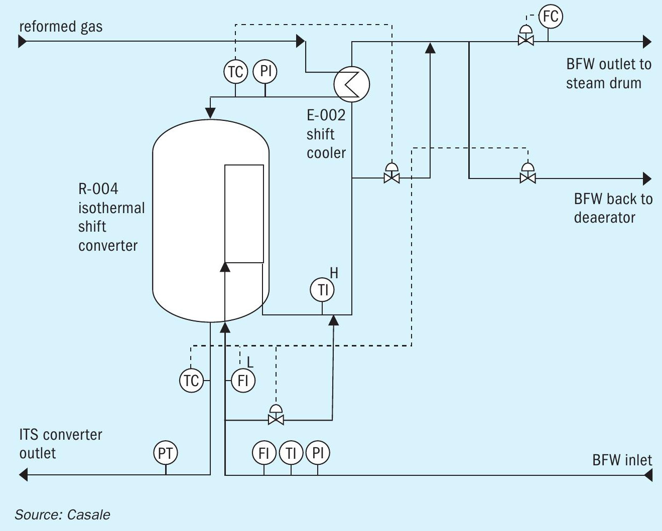
Fig. 5 shows a typical process flow diagram for a BFW heating scheme.
The make-up gas, available at battery limits, enters heat exchanger E-002, where it is cooled down to the appropriate catalyst inlet temperature (230°/260°C, depending on the catalyst age).
The gas then enters the shift converter (R-004) and flows in an axial-radial path, through the catalyst bed, where the reaction takes place. Boiler feed water flows in the plates, acting as boiler feed water heater, and removes the reaction heat.
The temperature of the reacting gas in the catalyst mass is monitored by means of three thermocouple bundles, located inside of the catalytic bed.
Additional thermocouples, located in the inlet and outlet pipelines, monitor the temperature of the inlet and outlet gas.
The converter outlet temperature is controlled by the water flow rate through the plates, and by means of bypass of the plates. Such control enables the converter to cope with variations in load and catalyst aging as well as with small changes of the plant feed type.
The temperature of the water outlet from the plates is monitored by a thermocouple. The saturation temperature should not be approached, in order to avoid water vaporisation in the exchange plates.
Advantages of the isothermal shift technology
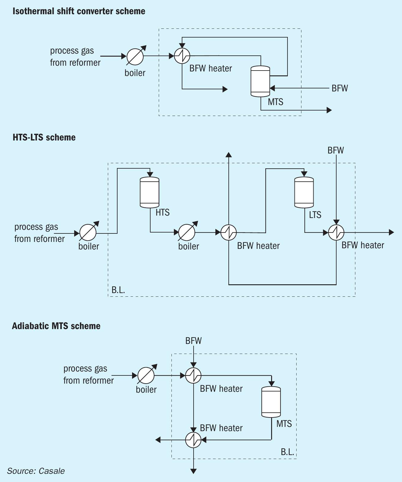
Fig. 6 shows three different possible configurations.
The main benefits of Casale isothermal technology can be summarised as follows:
l fewer items of installed equipment (higher operability and less maintenance);
l significant reduction in operating and installation costs;
l higher CO conversion with same catalyst volume;
l lower catalyst volume at fixed CO conversion;
l better catalyst utilisation;
l only one type of catalyst is required;
l Casale axial-radial flow minimises pressure drop across the converter.
The Casale isothermal design follows the best reaction path to optimise the converter performance. In fact, it maximises the CO conversion at a fixed catalyst volume or, at fixed CO conversion, it requires the less catalyst volume.
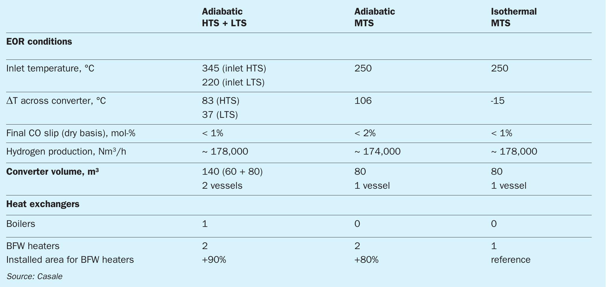
Considering the end-of-run conditions, Table 1 summarises the performance of the technologies analysed for a particular example:
As can be seen in Table 1, with the isothermal design, thanks to the better reaction path through the catalytic bed, at the same CO conversion of standard configuration (HTS + LTS) a significant saving in catalyst volume is achieved.
The CO conversion for the adiabatic MTS configuration is less than in isothermal design, with the same catalyst volume. In addition, since the adiabatic MTS works close to equilibrium conditions, in order to have a CO slip of less than 1% on dry basis, the installation of a cooling stage is necessary, like in the HTS + LTS configuration. So, only with the isothermal technology is it possible to perform the CO conversion in a single stage, minimising the number of installed equipment items, simplifying the process configuration and reducing the investment costs.
References
In addition to the adiabatic shift converters in operation, Casale has one isothermal MTS converter in a hydrogen plant in Russia, in operation since 2013.
Casale also has significant experience with the design and operation of isothermal methanol converters, which operate under very similar conditions, with 18 converters in operation.