Sulphur 398 Jan-Feb 2022
31 January 2022
Key considerations for converter upgrades
SULPHURIC ACID EQUIPMENT
Key considerations for converter upgrades
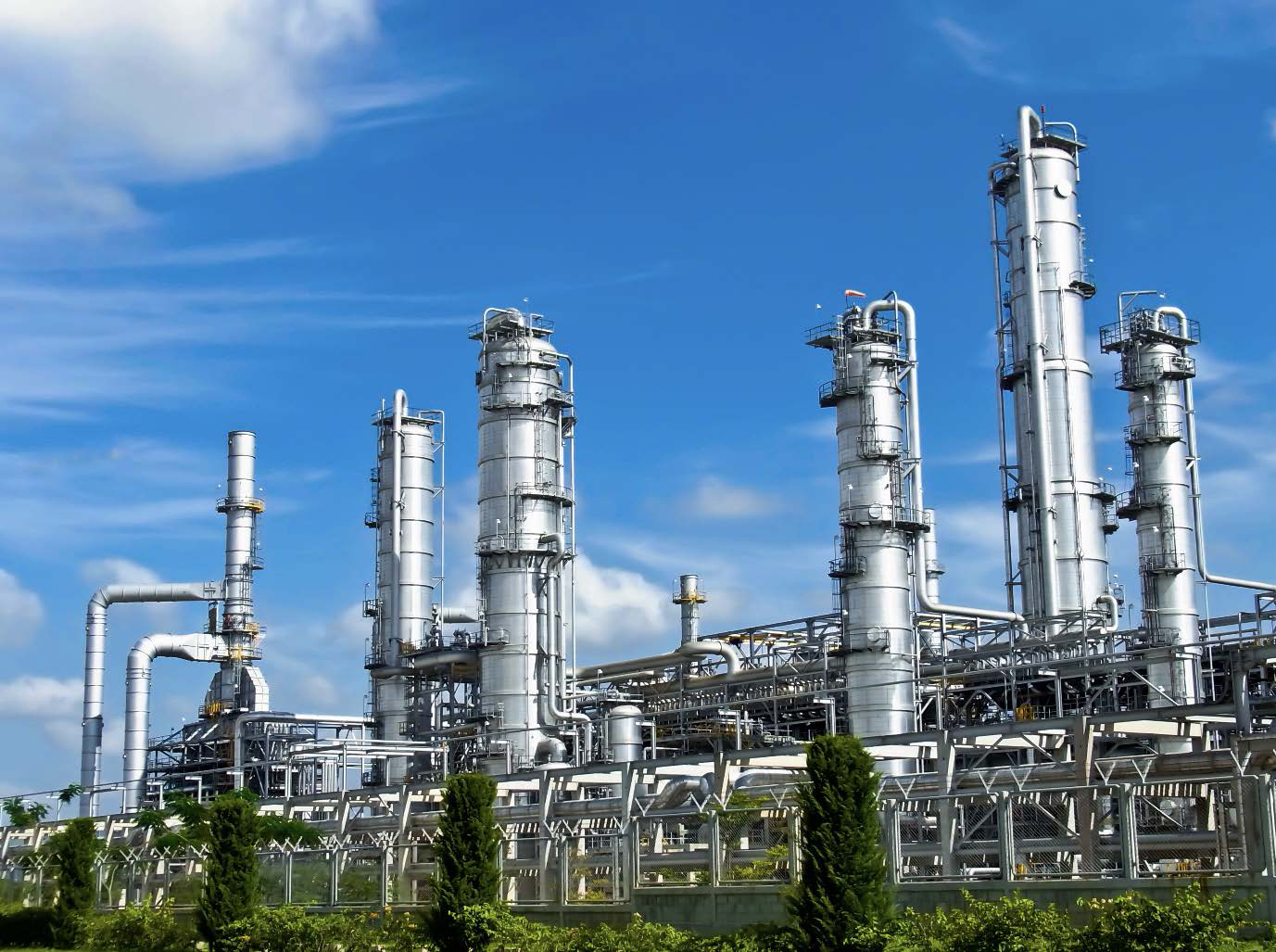
Catalytic converters are the heart and hub of sulphuric acid plants. Converter replacement of equipment that has come to the end of its life is an opportunity to make improvements to the performance, productivity, reliability, durability and plant emissions. NORAM discusses design and project execution considerations for SO2 catalytic converter replacement and Chemetics considers the challenges and opportunities of converter retrofits.
NORAM
SO2 catalytic converter replacement – design and project execution considerations
During the lifecycle of a sulphuric acid plant, there may be times when the performance of the plant needs to be improved e.g., to lower emissions of sulphur dioxide (SO2 ). Although a number of process alternatives exist for performance improvement, typically the most cost-effective way is to uspgrade the existing equipment such as the catalytic converter, which together with the catalyst is the heart of the plant and determines the SO2 emissions from the plant.
Converter replacement is typically required at about 20-40 years of age depending on factors such as SO2 gas strength, converter design and reliability concerns. Higher strength SO2 feed gases to the acid plant result in higher temperatures and shorter converter life. Older converter designs with cast iron posts and grids with a carbon steel shell may see deformation of posts, wall thickness reduction, sigma phase embrittlement, and shell bulging, necessitating replacement. When there are concerns about the mechanical integrity of the converter, a prudent owner may decide to replace it rather than risking a major failure.
Other reasons for replacing the converter include:
- the requirement to increase catalyst volumes beyond the capacity of the existing converter;
- conversion from single to double absorption;
- combining two converter vessels into one.
Project considerations for a converter replacement include SO2 emissions limits, specific tie-in points and dimensional limits, ergonomic requests, turnaround planning and duration of plant shutdown, existing equipment condition and logistics considerations. Design tools such as computational fluid dynamics (CFD) are used to evaluate velocity and temperature distribution in the catalyst bed and to confirm uniform gas distribution, whereas finite element analysis (FEA) is used for mechanical design.
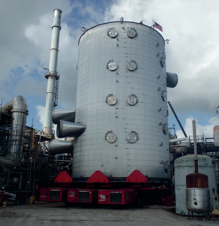
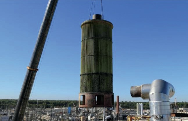
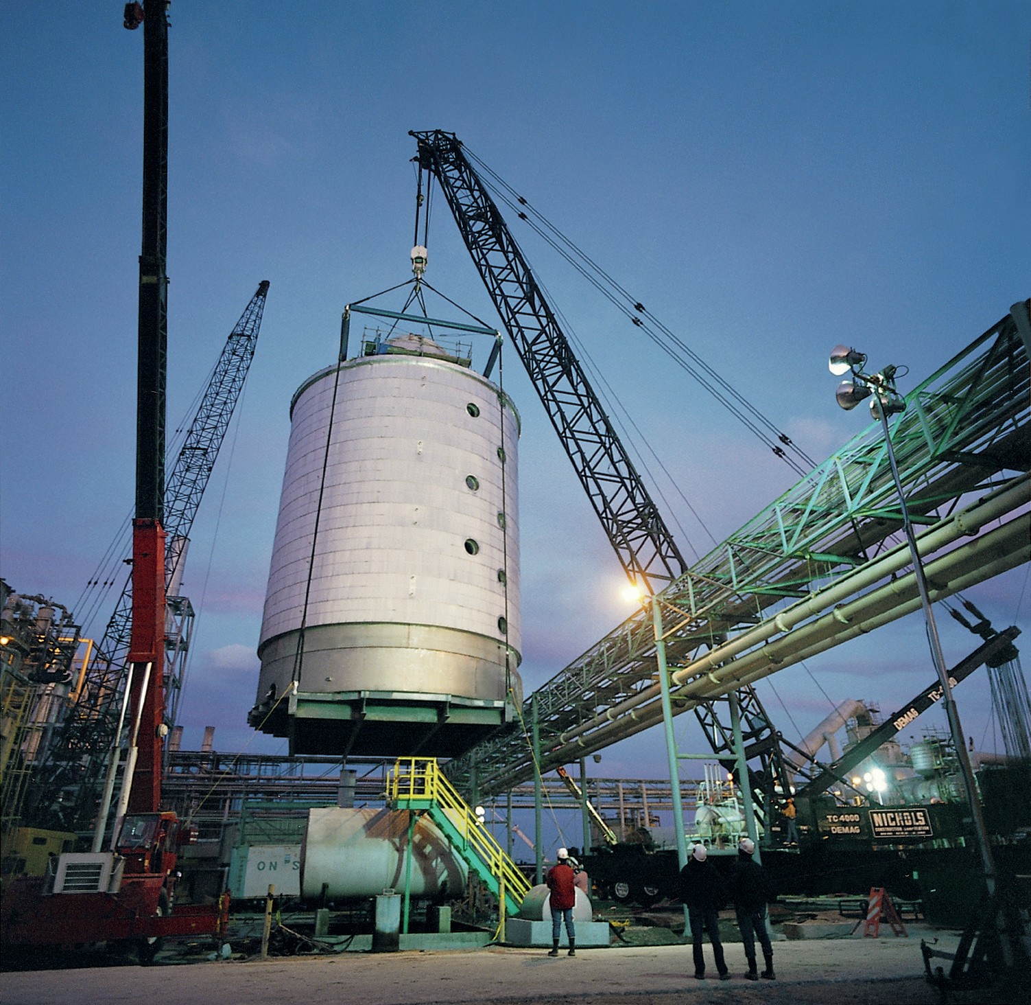
NORAM’s approach to converter replacement is to, where possible, make the converter in the shop and relocate on the same foundation (Fig. 1). For replacement converters NORAM typically designs the new converter diameter to be similar to the existing converter to match the foundation and tie-ins. Improved catalyst performance allows reduced emissions with the same diameter.
Although a new converter will typically improve the performance of the sulphuric acid plant, it cannot resolve upstream process issues. It is therefore important to ensure that the feed gas to the converter is within the design operating envelope to optimise performance, minimise emissions and maximise equipment life.
Good SO2 concentration control to the first catalytic pass is required to maintain an acceptable temperature profile, while feed gas temperature control is required to prevent acid condensation on the catalyst. Effective mist elimination upstream of the converter is required to prevent mist carryover, which may result in damage to the catalyst, fouling and high converter pressure drop as well as equipment corrosion.
SO2 conversion
A well designed and operated converter (inclusive of catalyst) reduces SO2 emissions from the acid plant. Emissions of sulphur dioxide are defined by the design of the catalytic converter, the production rate, catalyst selection (type, size, loading, volume, age and activity), operating temperatures and the interpass absorption tower efficiency.
Approximate rules of thumb for SO2 oxidation in the converter include:
- Temperature rise = % SO2 converted times 28°C (50.4°F).
- Incoming SO2 concentration = Total temperature rise in all four beds divided by 28°C (50.4°F).
- Conversion in first bed = about 60-65%.
- Maximum allowable temperature for the catalyst = 620 to 650°C (1,148 to 1,200°F)
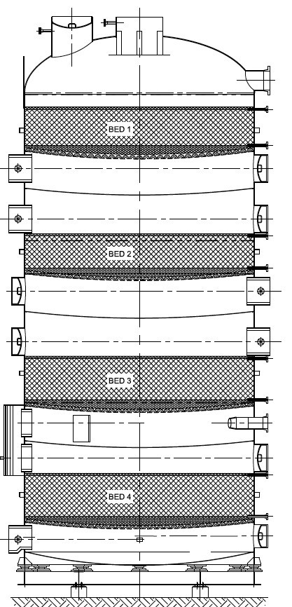
There are two basic types of sulphuric acid catalysts, standard vanadium pentoxide and enhanced catalyst e.g., caesium-promoted catalysts. SO2 emissions are also affected by the number of catalyst beds. Four catalyst beds are most common but other configurations are also available, for example, 3 beds or a 3+2 configuration.
The converter design will depend on the target emissions from the stack which are usually dictated by government regulations. An achievable target is 100-150 ppm.
Total SO2 emissions from the acid plant are made up of the SO2 leaving the converter plus contributions from stripping the acid in the final tower. Final tower SO2 slippage is therefore an important consideration, especially if there is a common interpass and final tower pump tank. With this configuration, SO2 will be transferred from the circulating acid in the interpass tower into the pump tank, from where it is transferred to the final tower where it will be stripped and end up as SO2 emissions, contributing up to 50-70 ppm SO2 to the total SO2 gas concentration in the stack.
Catalyst evaluation
Technical considerations when evaluating catalyst selection are based on the following:
- conversion per bed;
- inlet and outlet bed temperatures;
- pressure drop per bed;
- emissions in ppm.
Commercial considerations include:
- catalyst price;
- two-year warranty on conversion;
- pressure drop warranty at start-up;
- blower power cost over a 10 year period.
Rigorous comparison of quotes with identical design basis in terms of performance guarantees, catalyst conversion, pressure drop, and overall economics is required to identify the best fit.
Converter design
The selection of the correct converter design can reduce the project cost and improve performance.
New equipment should have a robust mechanical design and provide reliable operation, higher on-stream time, and lower maintenance requirements than the existing converter. The converter should be fabricated using suitable material of construction such as stainless steel.
Designs should be robust and reduce high localised stresses which could lead to premature failure and gas leaks. Rectangular nozzles should be avoided. Nozzles should be obround, elliptical or round to minimise stresses. The new converter should be designed according to local climatic and seismic conditions.
Where feasible, dimensional constraints and requirements should be considered to minimise ducting changes.
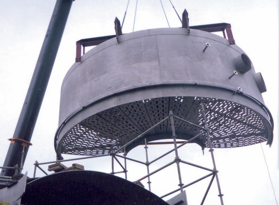
A key aspect of NORAM’s patented converter design is that it allows the use of the full cross-sectional area for catalyst loading (Fig. 2). However, if required, NORAM’s design is also able to accommodate the installation of gas-gas heat exchangers in the core to reduce pressure drop and space. With one internal gas exchanger it is still possible to use the full cross-sectional area for catalyst loading in the remaining two or three beds. For replacement converters, this is a powerful feature that increases the cross-sectional area for the same diameter.
Also, by using a catenary plate design, NORAM can build the modules in the shop for high quality control and then weld the modules together in the field.
Converter sizing
Converters are sized based on a superficial gas velocity through the catalyst bed, plot space available, shipping constraints, and pressure drop. The catalyst bed total pressure drops should be above 2″ (51 mm) WC to avoid gas maldistribution. Catalyst manufacturers specify a fairly wide superficial velocity range of 20-40 linear metres per minute at standard volume conditions.
A secondary consideration after conversion and pressure drop is shipping considerations and whether the size of the equipment is shippable in one piece. If the new converter size is very close to shipping limits it may be possible to reduce the size somewhat to make it shippable, provided it doesn’t compromise process performance.
The converter height is determined by several factors. Catalyst depth is specified by the catalyst manufacturer, based on the process requirements and conditions and according to the catalyst volume and type. The prescribed catalyst bed height should include an allowance for future capacity increase or more stringent emission limits.
Headroom above the catalyst is sized for operators and maintenance to enable loading and screening of catalyst.
Clearance between catalyst support plate and division plate is often determined by outlet duct size and shape but with sufficient clearance for maintenance inspection.
The radial orientation of the ducting for the new converter can be easily matched with the existing converter but ducting elevations could vary. New converters are often taller with more room for catalyst and inspection.
Pressure drop
Designing for lower pressure drop will reduce energy consumption of the main blower.
Converter pressure drop comprises:
- Nozzle pressure drops
– Design for <20% of catalyst DP for uniform gas distribution
– Typical pressure drop +/-12 mm (½ inch) W.C.
- Catalyst pressure drop
– Determined by converter design, catalyst type, catalyst depth
– Converter with core tube has higher pressure drop due to less cross-sectional area.
– Typical clean pressure drop from 75-150 mm (3-6 inches) W.C.
- Catalyst support pressure drop
– Support comprised of packing support plate, saddles, expanded metal, quartz rock or ceramic balls.
– About 12 mm (½ inch) W.C.
Converter configuration
Internal exchanger
The hot or hot interpass (IP) exchanger can be installed in a new stainless steel converter. This eliminates external equipment including concrete, ducting, insulation and simplifies the plant layout. It is typically a standard offering for new acid plants.
Manways and bypass ducts
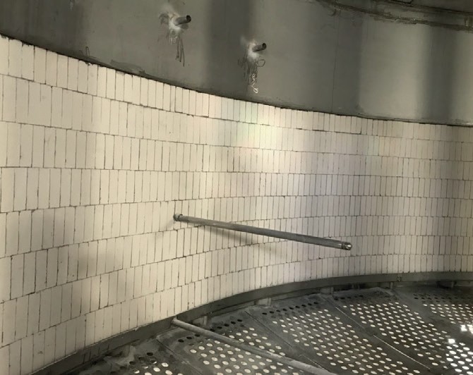
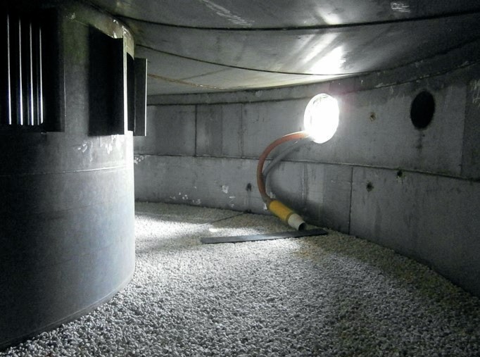
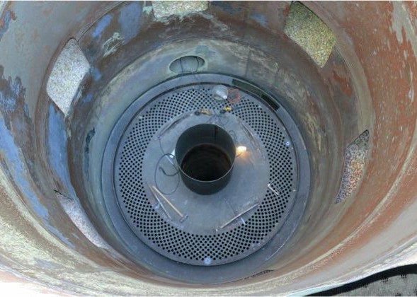
Manways should be large, typically at least 1 m diameter to allow for personnel access (Fig. 3). There should be two above the catalyst bed, one for personnel access and the other for equipment access. The start-up bypass duct can be on the outside of the converter for faster start-ups.
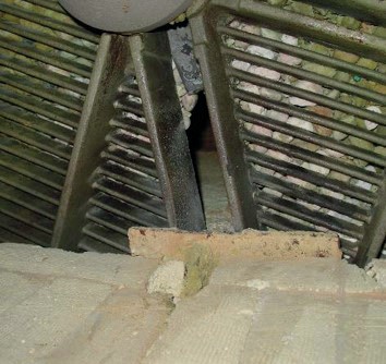
Refractory lining of the first pass
Some plants, more often sulphur burning plants, request to have refractory lining in the first pass of the converter (Fig. 4). Having a lining of insulating firebrick in the first pass of the converter provides additional heat retention so that when the sulphur furnace is shut down heat is retained for longer, allow for a longer shutdown before requiring fired heat input to start up again. It also offers some protection to the first pass outlet zone from the hot gases.

Bed and division plate support options
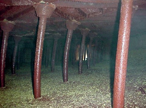
Converters were initially designed with a carbon steel shell and cast-iron grids and cast-iron posts for support. In the 1980s stainless steel converters appeared, with either dished beds or stainless-steel beams and posts.
The dished bed has some advantages:
- reduces the weight of the stainless steel required;
- can accommodate an internal gas exchanger;
- no internal support need if the converter is less than 7 m (22 ft) in diameter;
- can be shipped in modules for site erection of components.
- There are two support systems for dished bed converters larger than 7 m:
- a central cylindrical support reduces the cross-sectional area of the converter bed but allows radial gas flow from the core;
- a ring of stainless-steel posts allows the full cross-sectional area to be used and uses shell-side gas nozzles.
Project execution
Fabrication and shipping
After agreement on the design basis, size and shipping/construction strategy, NORAM will design and fabricate the converter.
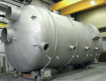
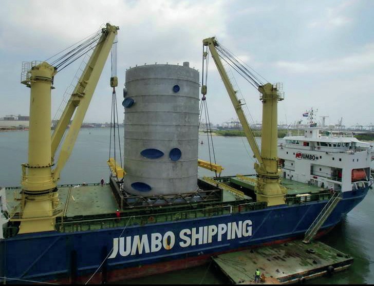
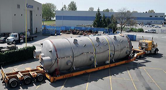
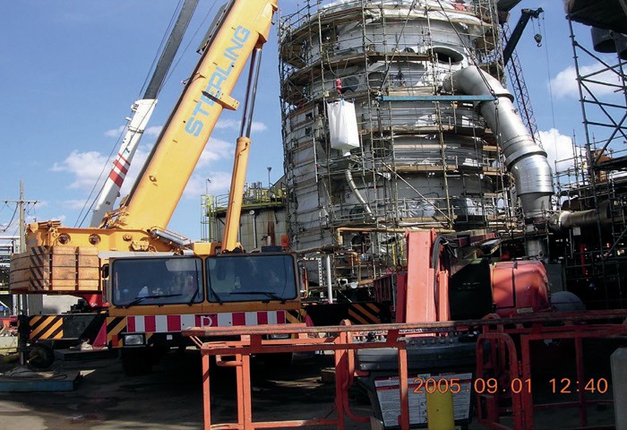
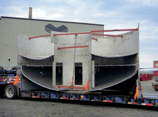
Depending on the size of the converter it can either be shipped in one piece or in multiple pieces. (Fig. 5).
Shipping in one piece is preferred as it maximises fabrication in a controlled shop environment, minimising field work and its associated costs and risks.
Converters of up to approximately 4.5 m (14-15 ft) in diameter can be transported by truck. Larger diameter converters can be transported by barge or ship. This option is typically more expensive than truck and requires more lifts.
Converters of 4.5-5.8 m (14-19 ft) in diameter could be shipped in “rings”. Converter rings require simple field erection. The number of circumferential field welds will be number of rings minus one.
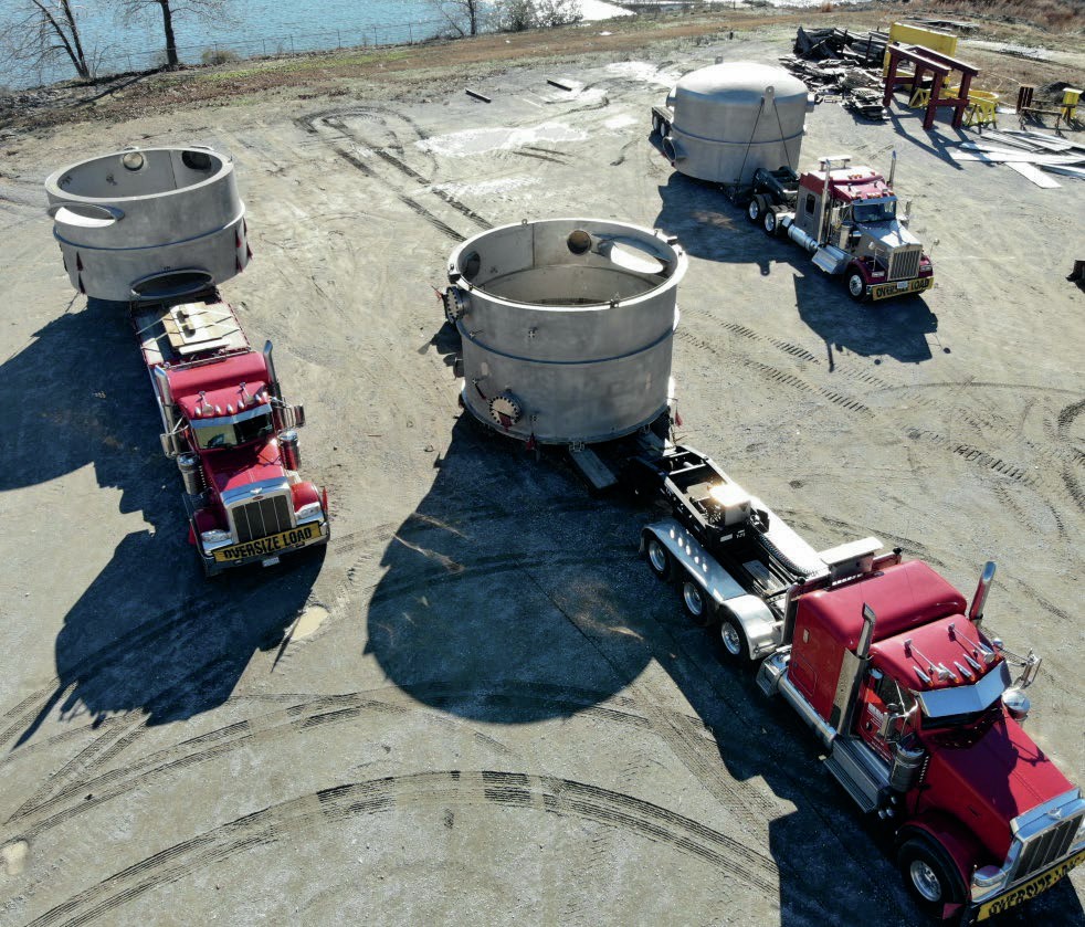
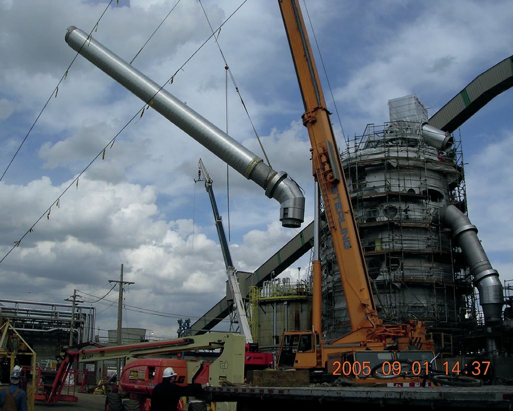
Converters with a diameter larger than 19 feet can be built in sections and shipped in pieces (e.g., 180° half ring sections or 90° sections consisting of four pieces per ring) and assembled on site.
Location of the replacement converter
There are two basic choices for the location of the replacement converter, using the existing foundation or a new location.
When using an existing foundation, prior to the shutdown, the new converter is erected or set near the existing converter. During the shutdown the converter is removed or demolished, and the new converter is lifted or wheeled in. It is preferable to insulate prior to shutdown if possible.
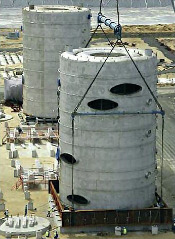
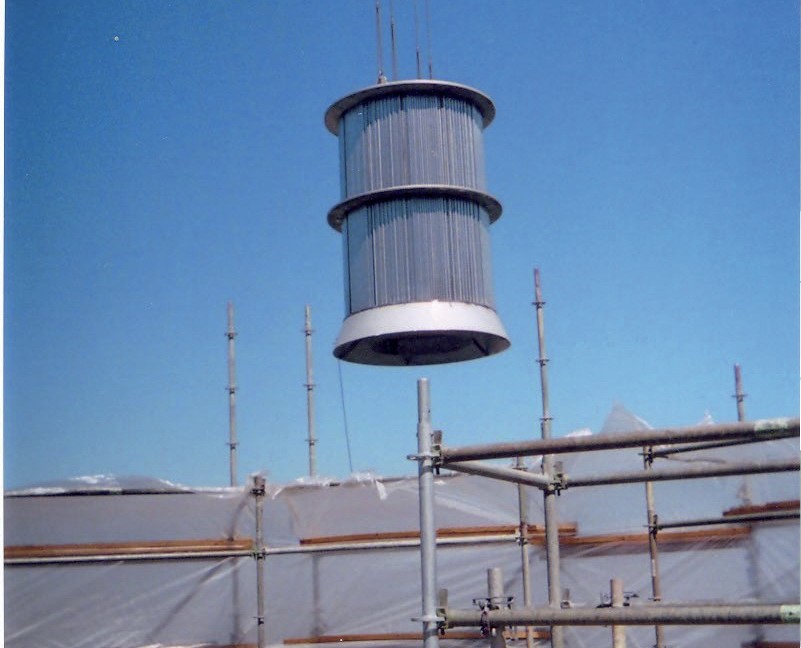
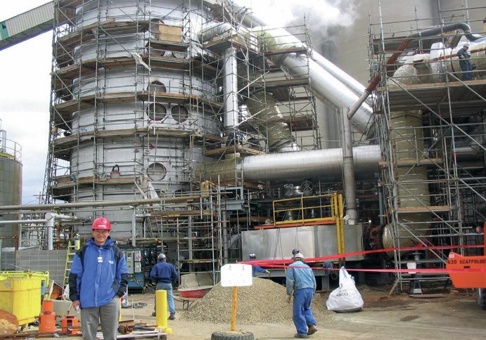
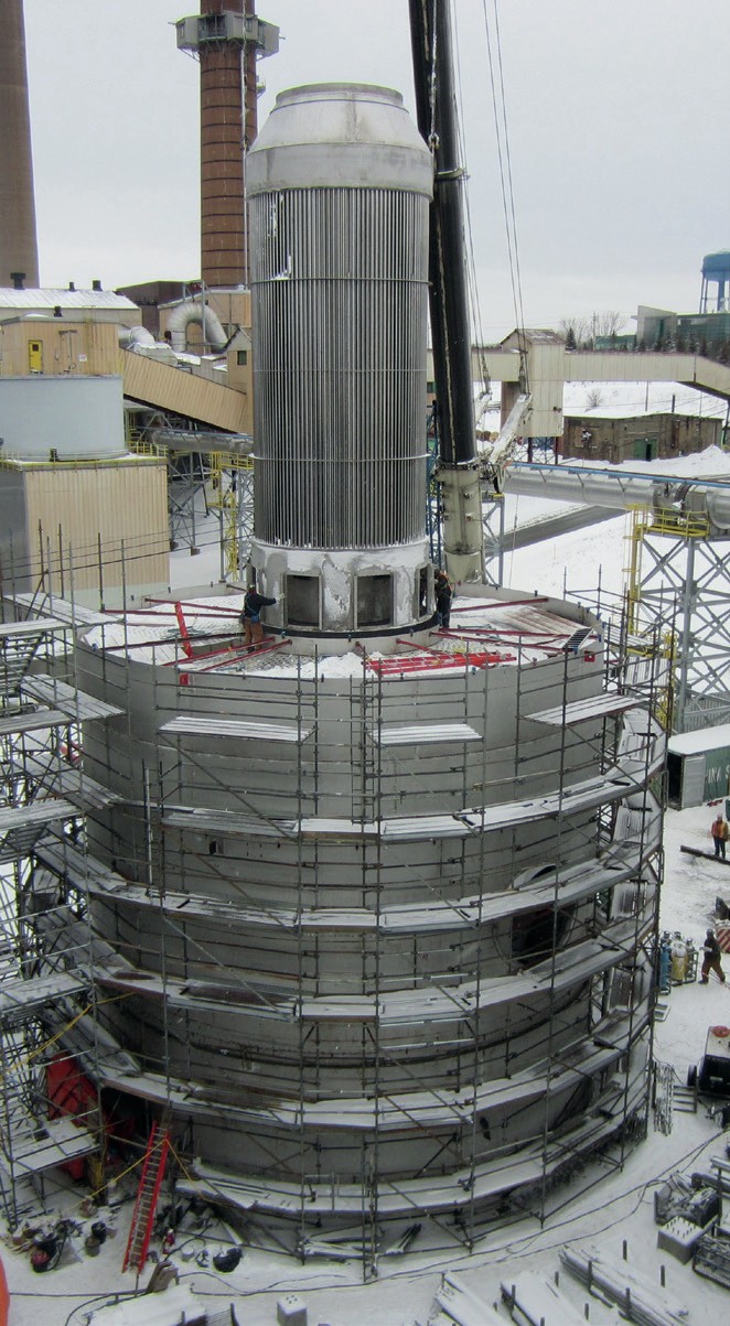
For a new location, prior to shutdown the new converter is erected or set on a new foundation and insulated (Fig. 6). New ducting is installed ready for tie-in. During the shutdown the new converter ducting is connected to the existing ducting. Finally, after start-up of the new converter the existing converter is demolished or moved.
Using the existing foundation is the preferred option in most cases. It retains the same plant footprint and requires less ducting changes but requires the ability to easily demolish and move the new converter into place and may require a longer shutdown.
Using a new location can reduce project schedule risk due to most of the work being done prior to the shutdown but is likely to be more expensive due to eight new ducts requiring connection with existing equipment. In addition, it changes the footprint of the plant and requires plot space relatively close to the existing converter to minimise costs.
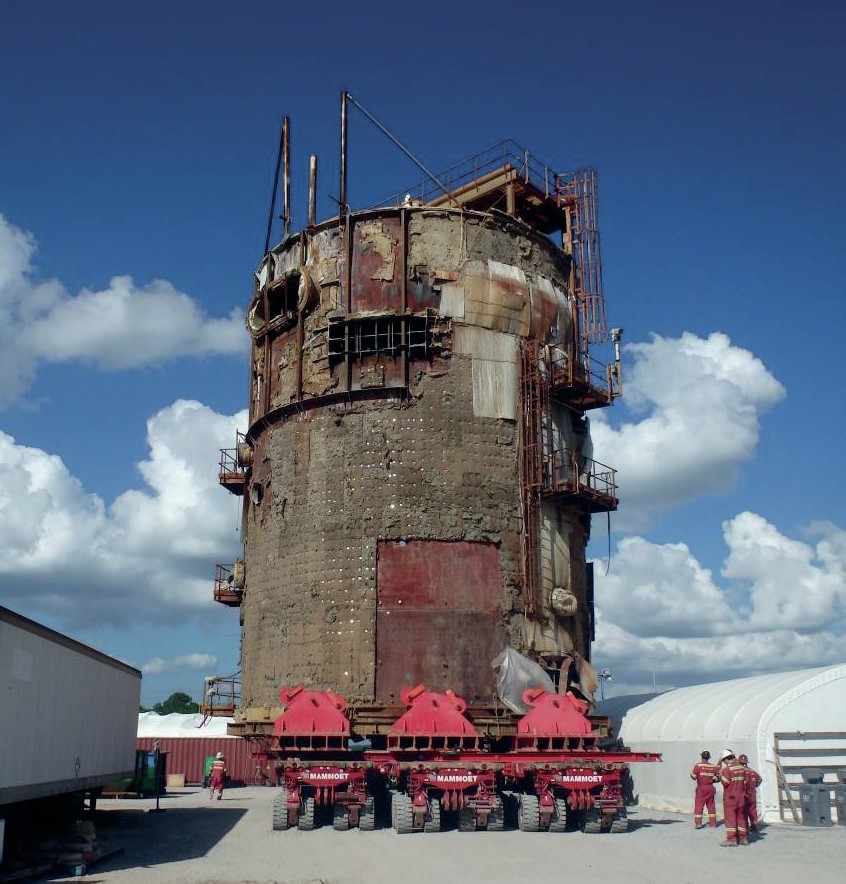
Demolition of existing converter
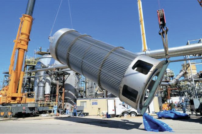
The main options for re-use of the existing foundation are to install beams under the converter and either lift, wheel or slide it out (Fig. 7). Alternatively, the converter can be demolished in place and taken apart in pieces.
Installation of replacement converter
For re-use of the converter foundation, the following options can be considered during the shutdown for installation of the replacement converter:
- Lift In
– Lift in insulated shell using lifting lugs on the top of the converter.
– Typically install quartz rocks and catalyst after.
- Wheel or slide in
– Wheel or slide in insulated converter onto the existing foundation
– Catalyst and rocks may be installed before or after the move
- Erect in place
– Converter modules are erected onto the existing foundation
– The converter is insulated, catalyst and rocks installed.
CHEMETICS
Converter retrofits: challenges and opportunity
The global sulphuric acid industry is currently faced with challenges and opportunity simultaneously. Internal and regulatory requirements for lower emissions and greater efficiencies are commonplace. At the same time, the vast majority of global sulphuric acid plants are approaching the age where major equipment is reaching endof-life and will need to be replaced. Catalytic converters are the hub and heart of any sulphuric acid plant and virtually all of the major plant equipment is directly connected to the converter. When the time comes to replace an old converter, it should be treated as an opportunity to implement and benefit from several possible improvements to the performance, productivity, reliability, durability, and emissions of the plant. Common achievable plant upgrade goals are as follows:
- increase the SO2 to SO3 conversion rate/ lower SO2 emissions;
- reduce the SO2 /SO3 emissions due to internal and external ducting, nozzle or converter leaks;
- increase capacity; l reduce pressure drop;
- simplify plant layout;
- improve equipment durability;
- minimise maintenance work and plant downtime;
- increase time between turnarounds.
Over 40 years ago Chemetics developed, patented, and presented the modern radial flow, all welded, stainless steel converter (Fig. 1) to the global sulphuric acid industry. This novel design helped achieve all the aforementioned goals for new plant and retrofit projects. Additionally, Chemetics has developed modular execution strategies to minimise site assembly/installation time, while also allowing the maximum location and layout options. This article explores the strategies and design elements that Chemetics applies to achieve the above goals on converter retrofit projects.
Radial flow all-welded stainless steel converter
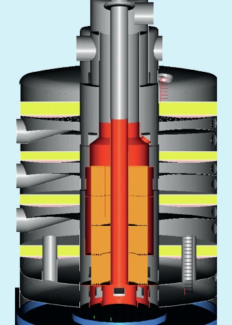
The introduction of the radial flow all-welded, stainless steel converter was a significant upgrade over the common original grid-andpost design. The all stainless steel construction provides a robust and lightweight converter without the need for any internal brick lining. The significant reduction in mass and inherent mechanical flexibility during times of large differential thermal expansion also results in reduced plant warm-up time for cold start-ups. All joints and seams are fully welded which eliminates any interbed leaks/bypass. The duct nozzles apply a proprietary design that allow for zero leaks to atmosphere, even after decades in service, thus eliminating a repetitive failure mode found on both historical carbon steel brick-lined grid-and-post converters, as well as their modern stainless steel grid-and-post replacements. The radial flow design applies a centre core to the converter (Fig. 2) that is used to feed gas radially from the centre core to each catalyst bed. This results in uniform gas distribution and complete and efficient use of the available catalyst in the converter. Hot spots or high velocity areas that can lead to local catalyst degradation are eliminated. These features contribute to lower required catalyst loadings for the same plant performance and lower converter pressure drops. By comparison, the grid-and-post design is prone to inter-bed leak/bypass between the stacked components, particularly as the converters age and experience shift and internal settling (Figs 3 and 4). In addition, the grid-and-post converters feed gas to the beds from a single shell nozzle, this can result in non-uniform gas distribution.
Chemetics recommends designing converters with consideration for future potential capacity and emissions goals. With minimal additional investment, future catalyst capacity allowance can be included to address potential future needs. The Chemetics design leaves a completely open and accessible catalyst bed area. This allows very easy access for adding, changing, or screening catalyst.
The result of all the improvements that came with the Chemetics converter design have enabled acid plants to increase their SO2 /SO3 conversion rate, reduce SO2 / SO3 emissions due to internal and external leaks, minimise maintenance costs and plant downtime, and improve equipment durability and longevity. The proof is in the performance. Chemetics converters regularly have zero mechanical maintenance or external leaks for decades after installation.
Insulation
An underappreciated area that is crucial for converter performance is the insulation system. Unlike small vessels and ducting, the large size of the converter along with the very high metal temperatures results in drastic thermal expansion of the converter shell, but not in the cladding. For example, in a 30-ft diameter converter the shell will grow approximately 1-ft in circumference relative to the cladding. With a simple cladding system this leads to failures in the cladding weather barrier after multiple thermal cycles, and eventual water ingress and loss of effective insulation. To rectify this, Chemetics has developed a floating cladding insulation system that avoids cyclic stresses to keep the insulation system intact through decades. Poor insulation leads to fast heat loss, reducing both steam production and the duration of a practical hot shutdown. With an intact insulation system, hot standbys of over 16 hours are common.
Catalyst selection and loading
The catalyst world is constantly evolving. Continuous advancements in composition and shapes create more options for greater overall or targeted performance (conversion, pressure drop, temperature window, durability etc.). In some circumstances certain improvements to existing plants/converters can be made by changing the type and/or loading of catalyst. However, this depends on whether the original design accounted for potential future additional capacity, and it often also requires significant alterations to other major process equipment such as gas exchangers and towers. When replacing a converter, the opportunity arises to design around the optimal available catalyst options and loading in order to achieve the plants current and future goals (emissions, plant capacity etc.). Although this will still often require changes to other process equipment, Chemetics treats this is as an opportunity to modernise and simplify the plant layout and achieve additional goals, which is expanded on further in the next section.
Internal gas exchangers and superheaters
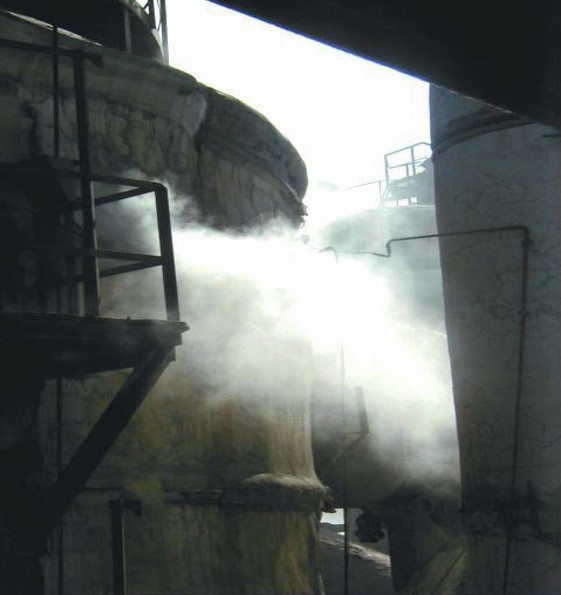
With traditional antiquated converter designs, gas exchangers and superheaters are all placed external to the converter with a labyrinth of ducting inter-connecting all the various equipment. The result is a costly plant with an overly complex layout and excessive process containment surface area where leaks will inevitably occur. Hot gases combined with rigid converter/ ducting designs lead to very high stresses and subsequent material failure as the bed 1 and 2 outlet temperatures push the materials of construction to their maximum limits, resulting in SO2 /SO3 leaks to the atmosphere (Fig. 5). Common leak points are converter/gas exchanger/superheater/ducting nozzles as well as ducting elbows and expansion joints. For these plants the perpetual struggle and related maintenance costs to control these leaks is an unfortunate reality.
The design of the Chemetics radial flow converter includes an internal core where gas exchangers and superheaters can be placed (Figs 1 and 6). In a typical Chemetics converter there is enough space for multiple pieces of heat exchange equipment. The gas exchangers are designed so that the in and out flows align directly with the associated converter bed flow, all within the converter core. By situating gas exchangers internal to the converter, the process containment surface area of the plant is significantly reduced and all potential leak points for the internal equipment are eliminated. This approach eliminates the gas exchanger and superheater shells, all ducting, insulation, and nozzles associated with the internal equipment. In essence, all the parts that cause the vast majority of the leaks are eliminated. An additional benefit from the elimination of major ducting runs is the reduction in system pressure drop.
Chemetics has successfully used internal gas exchangers since 1983, with over 30 installations. The one question that remained regarding this approach was the viability of replacing an internal gas exchanger that reaches end-of-life prior to the converter. For the replacement of an external gas exchanger the execution is well known and documented. For replacement of an internal gas exchanger the execution plan was developed by Chemetics long ago and is quite straightforward. The converters are designed specifically to allow this to occur. Fortunately, from 1983 until 2015 there was never a need to replace any of the Chemetics designed internal gas exchangers. It turns out that by eliminating the shell, insulation, ducting, and nozzles and associated stresses on the gas exchanger (as well as only installing equipment that cannot have acid dew point condensation within the converter core), this has extended the life of the units.
In 2015 the opportunity for such a replacement presented itself. A North American client with a sulphuric acid regeneration (SAR) plant and a Chemetics converter installed in 2006 needed to replace its internal hot gas heat exchanger (HHX). The plant process is somewhat unique in that combustion is enriched with oxygen. It was determined that the oxygen-enriched combustion products were attacking the HHX at its high metal temperature. The converter was in good shape and the decision was made to replace the internal HHX with a new unit with upgraded metallurgy.
Chemetics worked with the client to plan and execute the replacement project. The project involved removing the core duct assembly (Fig. 7) to expose the top of the HHX (Fig. 8). Baffle seal plates were removed and then the HHX was lifted and removed as a complete unit (Fig. 9). The reverse sequence was then executed to install the new HHX (Fig. 10). The project was a success and completed comfortably on schedule in three weeks, within a five-week overall shutdown. This replacement project demonstrated that with proper planning, the replacement of an internal gas exchanger is completely viable and straightforward.
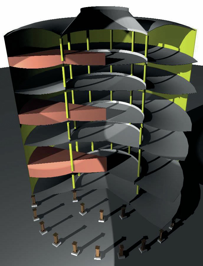
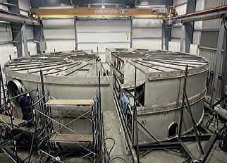
Modular converter assembly
The converter is by far the largest piece of equipment in a sulphuric acid plant, with some of the largest reaching 100 ft (30 m) high and over 66 ft (20 m) in diameter. Replacement projects can be complex and should be planned thoroughly and well in advance. The old converter must be demolished, and the new converter installed with minimum plant downtime and operational disruption. Replacement projects are much more challenging in every aspect, when compared to erecting a converter for a new plant build.
Replacing a converter with the older grid-and-post design can limit options regarding location and layout. Moving a fully assembled grid-and-post converter is nearly impossible, as all the internal components are loosely stacked and susceptible to shift. Typically, it is recommended that grid-and-post converters are assembled where they will remain and operate. Replacing with a grid-and-post converter in the location of an existing converter is rarely a viable option. The amount of outage time required to demolish the existing converter, assemble a new grid-and-post converter, and then tie in all the ducting would be excessive and impossible to justify for virtually any plant. For these reasons converters that are replaced with a gridand-post design are most often planned for a new location. This is greatly dependent on whether there is available plot space. The benefit to a new location is that the required outage time is minimal as the new converter is assembled during plant operation, leaving only the ducting tie-in’s to be completed during the outage. The downside is that a new foundation is always required, and ducting run length will increase along with pressure drop.
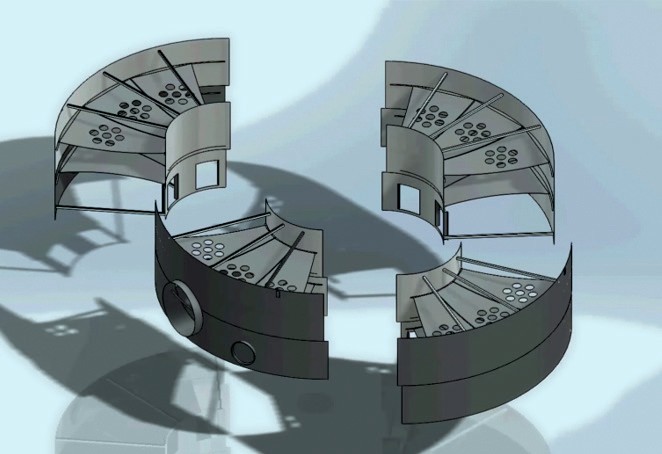
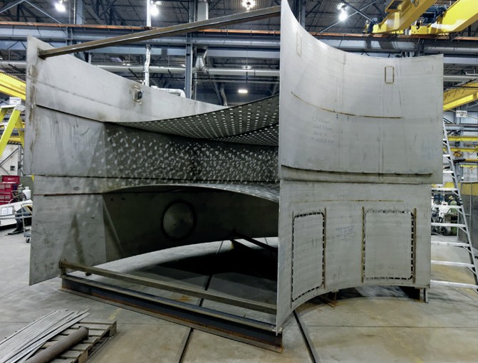
The modern Chemetics radial flow, all welded, stainless steel converter allows for a full spectrum of viable location/layout options. Due to its all stainless steel construction, the Chemetics converter will always be lighter than any stainless steel or carbon steel, brick-lined grid-and-post converter that is being replaced. This means that the existing foundation can be re-used if it is in decent condition. The other related benefit to this design is that it lends itself to a modular fabrication/assembly strategy. The converter can be delivered to site in modules on trucks (Fig. 11). The modules are sized to fit the shipping envelope and maximise the shop fabrication work while minimising the field work. The converter modules are typically 12 ft (3.7 m) high and are designed to combine in levels (Fig. 12). Each level can be thought of as a layer to a cake, with a converter often having 5-7 levels. Each level may consist of only two half-ring modules (Fig. 13) for smaller converters, or several pie-shaped modules (Fig. 12) for larger converters. The converter will be assembled in sequence, one level at a time, starting with the bottom. Each level is preassembled from the modules then lifted and fit as a complete piece (Fig. 14). The modules each contain some core and shell segments connected by baffle/grid and or head material, resulting in excellent stability for shipping and field handling/assembly (Fig. 15). This execution model allows for up to 85% of the overall converter welding and 90% of the fitting to be completed in a fabrication shop. The remaining site work requires a small crew size and will result in a high quality converter due to the dimensional accuracy of the modules. Maximising the shop fabrication component of the project maximises the quality control and minimises the schedule duration and risk.
Chemetics owns a state-of-the-art fabrication facility in Pickering, Ontario, Canada where converter modules and other process equipment are manufactured. The equipment is fabricated to the highest quality standards based on 60+ years of experience supplying the global sulphuric acid industry. Chemetics also regularly works with third party fabricators local to the clients’ site, depending on the location, and to minimise shipping costs where appropriate. As a fabricator, Chemetics is able to work closely with third part fabricators to ensure they perform at the same high level of quality.
If the client chooses to install the new converter in a new location the modules will be assembled on the new foundation while the plant is operating, with new ducting tie-ins completed during the outage. This is the option with the shortest required outage (approximately two weeks).
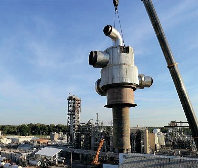
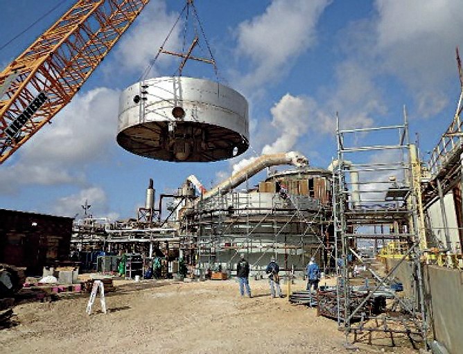
The option that becomes available with the Chemetics modular approach is that the new converter can be placed in the location of the old converter. This is accomplished by assembling the converter on a grillage in a temporary location adjacent to the plant while in operation. The converter internals will also often be installed during this time prior to the outage. During the outage the old converter is demolished/ removed, and the new converter is either slid or lifted into place. The sliding option is often chosen when there is a clear path of ground access. The lifting option (Fig. 16) is chosen when there is no sliding access and an appropriate crane is available. Due to the weight, the crane will lift from the grillage which would be designed accordingly. The grillage is permanent and will interface with the existing foundation. The final step is to complete the ducting tie-ins. The Chemetics converter can be designed with 360-degree freedom for nozzle locations, therefore ducting modifications are typically minimal. With proper planning this execution model can be completed during a reasonable and typical annual outage duration (approximately four weeks).
Summary
Converter replacement projects can be more complex and challenging when compared to the supply of a new converter and plant. However, with this challenge there also comes the opportunity to realise various goals to upgrade an existing plant. Since the introduction of the modern radial flow, all welded, stainless steel converter this technology, Chemetics has designed and installed approximately 70 converters globally, including new plants and retrofits. Most of the retrofits have occurred in the past 15 years, as many of the world’s sulphuric acid plants have begun to reach a critical age. Virtually all these converters were supplied with the Chemetics modular approach which has produced exceptional results. Chemetics has a proven track record and can support the client from concept to installation and commissioning.
As the converter in your plant approaches end-of-life, planning ahead and selecting a reputable technology vendor with significant converter retrofit experience is critical. The correct vendor can ensure a successful project that maximises return on investment, minimises disruption to operations, and positions the plant to meet all current and future performance goals.