Fertilizer International 508 May-Jun 2022

31 May 2022
Clean power at sulphuric acid plants
SULPHURIC ACID TECHNOLOGY
Clean power at sulphuric acid plants
Heat recovery systems at sulphuric acid plants have been providing carbon-free energy for decades now and continue to improve. There is also potential to combine the clean power generated at acid plants with hydrogen production from water electrolysis. This could provide the basis for green fertilizer production.
CHEMETICS
The green fertilizer complex
In this article, Chemetics introduces its green fertilizer complex concept. This integrates a sulphuric acid plant with green hydrogen and ammonia production to deliver carbon-free ammoniated phosphates at low cost with low emissions (Sulphur 399, p39). This practical solution for operators is outlined below.
Typical MAP/DAP fertilizer complex
In a typical phosphate fertilizer complex:
- Sulphur and ambient air are used to produce sulphuric acid
- This in turn is reacted with phosphate rock to produce phosphoric acid
- The phosphoric acid then reacts with ammonia to produce monoammonium phosphate/diammonium phosphate (MAP/DAP) or NPK/triple superphosphate (TSP) products.
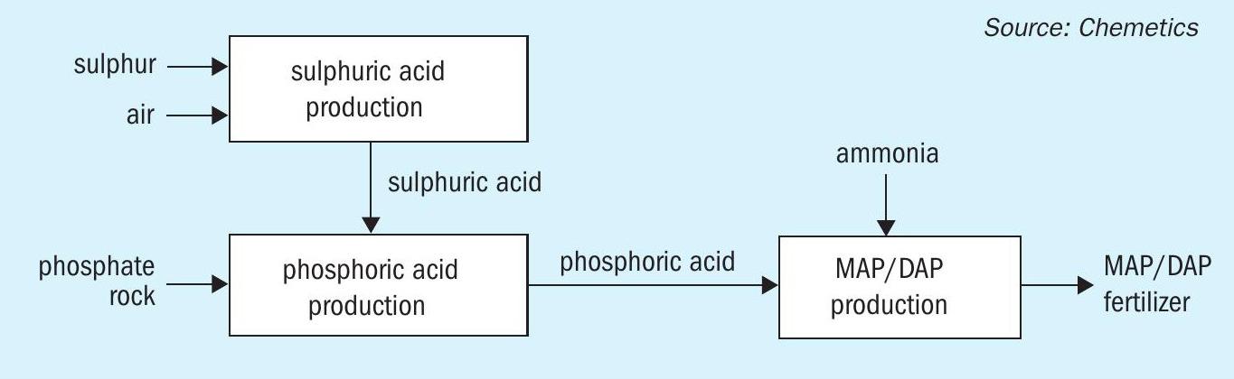
A simplified version of this process is shown graphically in Figure 1.
Power generation and avoiding emissions
In this concept, the energy released in sulphuric acid production is recovered as high pressure (HP) steam. This is used to generate power to operate the other units in the complex. Any excess power – which is available in most cases – can also be sold externally. To avoid CO2 emissions, it is also necessary to install an indirect drying process (e.g., steam drying) in the MAP/ DAP granulation plant, instead of the direct-fired dryers that are more commonly used.
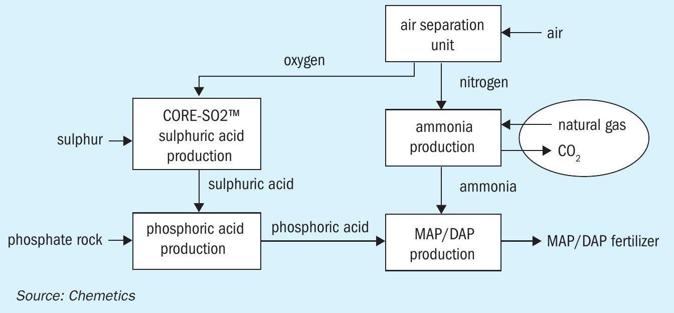
Integration of ammonia production
Further integration is possible when ammonia production is added to the complex (Figure 2). In the conventional steam methane reforming (SMR) process, ammonia is manufactured by combining hydrogen from natural gas with nitrogen typically supplied via an air separation unit (ASU).
The use of an ASU significantly reduces the amount of process gas – which subsequently requires purification – leaving the reformer. It also allows other hydrogen sources to be easily incorporated. This lineup (Figure 2) offers additional benefits as the by-product oxygen from the ASU can now be used in a CORE-SO2 sulphuric acid plant.
In this integrated production process, no imported electrical power is required as energy released in the sulphuric acid and ammonia production units provides sufficient power for the entire complex. Nevertheless, it obvious that the conventional SMR ammonia process will still generate significant amounts of CO2 due to its use of hydrocarbon feedstocks.
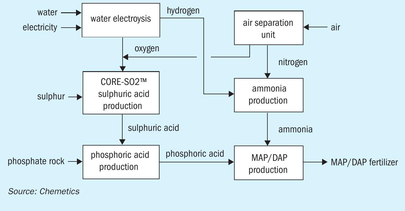
The green fertilizer complex
To make the fertilizer complex carbon free, it is therefore necessary to eliminate the CO2 emissions from the production of ammonia. This is achieved by supplying a different carbon-free source of hydrogen. This is referred to as ‘green hydrogen’ when produced via water electrolysis using renewable energy.
Several green hydrogen production options exist. Both polymer electrolyte membrane (PEM) and alkaline water electrolysis are already used at industrial scale, for example, while solid oxide electrolysis, which operates at higher temperature, also holds promise for the future.
All these types of electrolysis technology split water into hydrogen and oxygen. The hydrogen generated is used as a feedstock for ammonia production, while the by-product oxygen (as with the ASU unit) can be used to produce sulphuric acid. This additional oxygen source can therefore be used in two ways – to produce more sulphuric acid or reduce the size of the ASU. The resulting green fertilizer production process is shown in Figure 3.
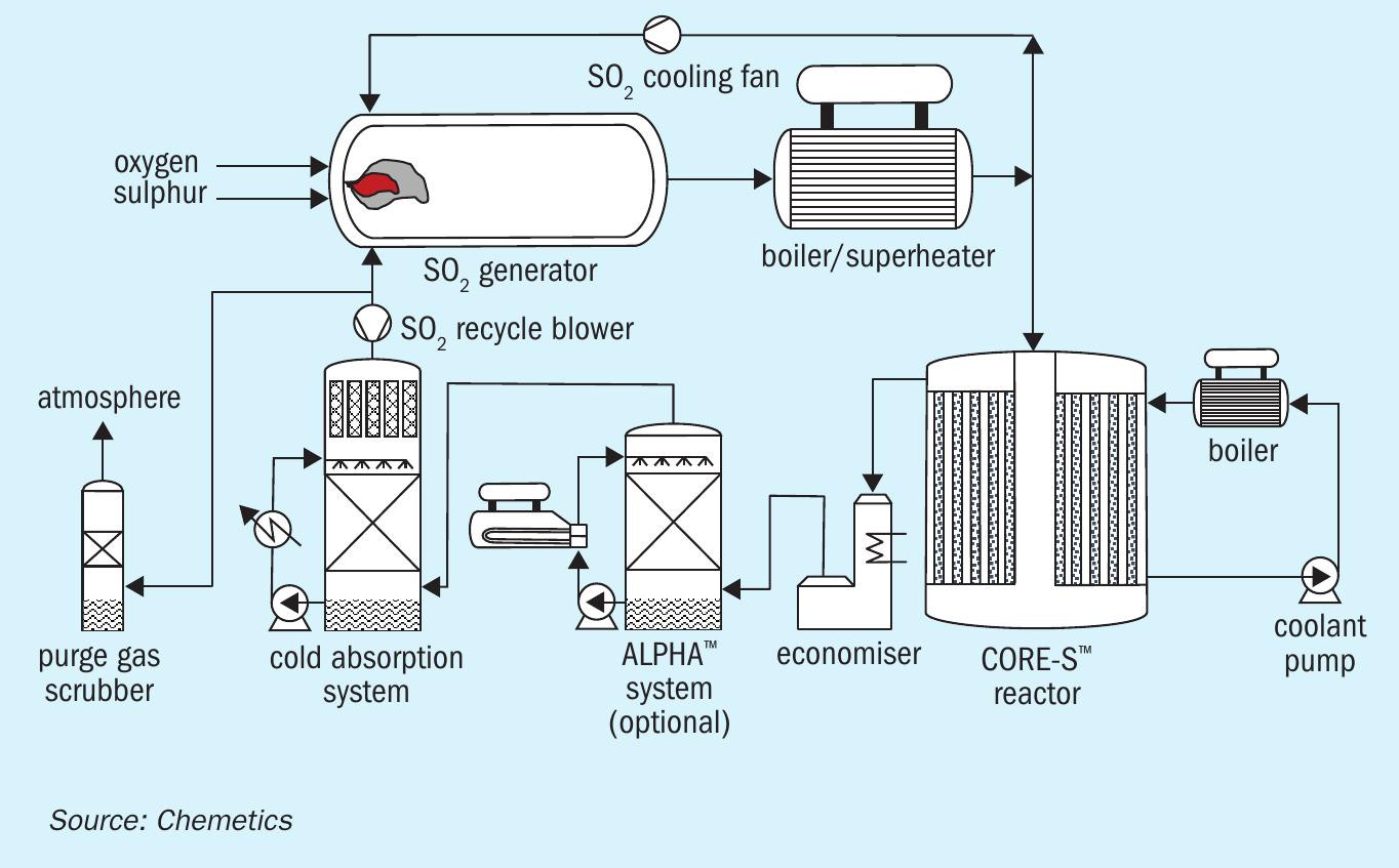
The CORE-SO2 process
At the heart of this fully integrated complex is Chemetics’ CORE-SO2 process (Figure 4). This takes full advantage of the ‘free’ by-product oxygen generated by water electrolysis – by combining this pure oxygen source with sulphur to produce sulphuric acid. CORE-SO2 also provides all the power necessary to run all unit operations except the electrolyser.
The resulting fully integrated green fertilizer production complex – which now only uses air, water, sulphur and phosphate rock as raw materials – is capable of producing fertilizers without any CO2 or SO2 emissions.
Additionally, in locations with a limited fresh water supply, excess energy from the CORE-SO2 plant can power a desalination plant to generate high quality water for the electrolysis unit and steam boilers from sea water or brackish water.
It is worth noting that a conventional fertilizer complex (Figure 2) can be incrementally switched over to the green hydrogen process without any changes to the other operating units being required. In this way, on-site green hydrogen capacity can be gradually ramped up to replace hydrocarbon-based capacity, as and when additional renewable energy sources become available. As a further benefit, the sulphuric acid plant will generate lower sulphur emissions as green hydrogen output increases, as less inert gases (present in the oxygen from the ASU) will enter the process.
Optimising energy integration
The integration of the complex is not complete without optimising energy integration. The sulphuric acid and ammonia processes both produce excess energy. Most of the energy from high-temperature sources can be captured and used to produce superheated high-pressure (HP) steam. For a DAP-producing complex without an SMR, combined steam production at 60 bar(g) and 500°C generates approximately 1.401.45 kg steam/kg sulphuric acid.
Within the complex, deaerators, sulphur melting, phosphoric acid evaporators and the MAP/DAP granulation plants also require low-pressure (LP) steam at 5-7 bar(g). This is generally provided by combining steam extraction from the turbine-generator with steam generated by the ALPHA™ system in the sulphuric acid plant.
The process selected for the phosphoric acid plant is an important deciding factor for LP steam requirements. This is because different processes such as di-hydrate (DH), hemi-hydrate (HH), hemidihydrate (HDH) will produce phosphoric acid at different concentrations (28-44%).
Consequently, if the main reactor generates phosphoric acid at higher concentrations – due to process selection – the phosphoric acid evaporators will require far less steam to reach the final merchant grade acid (MGA) concentration. A lower LP steam requirement also means the steam turbine can generate more electrical power as less (or no) steam need to be extracted. This is beneficial as it allows more base-load power to be dedicated to water electrolysis at the complex.
The recovery and use of the low-grade heat available at various units (e.g., by using a hot water network) offer further opportunities for energy integration. Although outside the scope of this article, these should be reviewed at an early stage in any new project.
Chemetics’ CORE-SO2 process is setting a new benchmark by delivering a step change in emissions reduction for sulphur dioxide and sulphuric acid mist. The process also offers compelling economic advantages in terms of lower capex and opex resulting from small stack gas volumes. These economics are further improved by integrating the process to take advantage of the ‘free’ by-product oxygen available from other units. Importantly, the CORE-SO2 process, when fully integrated within a green ammonia plant, enables the production of carbon-free fertilizers at low cost and without sulphur emissions.
PEGASUS TSI
Clean energy from sulphuric acid production
This article outlines the technical and economic feasibility of utilising clean energy from a sulphuric acid plant to produce green hydrogen in a fertilizer complex. This, in turn, can be used to produce green ammonia.
Clean energy production
An industrial fertilizer complex offers good potential for clean energy production. This can be realised by using the energy recovered during sulphuric acid production to generate medium-pressure steam for clean electricity.
By installing heat recovery systems in two sulphuric acid plants of 3,400 t/d capacity, for example, it should be possible to generate an additional 300,000 lb/hr of medium-pressure (MP) steam, according to our calculations. This can be used by a condensation steam turbine to generate 24 MW of net electric clean power.
Green hydrogen
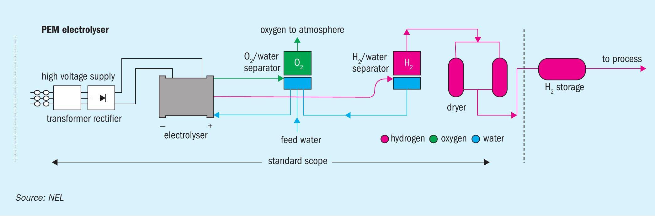
The clean power obtained can then be used to produce green hydrogen via water electrolysis. There are two industrial technologies available to do this: alkaline electrolysis (AEL), with a temperature and pressure below 80°C and 30 bar, and proton exchange membrane (PEM) electrolysis, with temperature and pressure lower than 100°C and 200 bar (Figure 1) .
AEL electrolysis units typically have a lower capital cost. Comparable PEM units, although requiring higher capital investment, are more efficient and can operate at higher current densities. In general, water electrolysis can deliver lower production costs at higher hydrogen production capacities.
With 24 MW of clean power, a PEM electrolyser (Figure 1) can potentially generate 8.3 t/d of green hydrogen (3,000 t/a). This can be used to produce green ammonia and, subsequently, granular mono-ammonium phosphate (GMAP) fertilizer.
Green ammonia
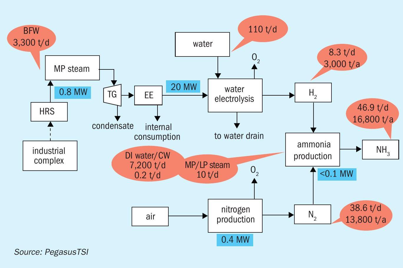
In our example, the 3,000 t/a of green hydrogen generated is used to produce 16,800 t/a of green ammonia at a phosphate fertilizer production complex (Figure 2). Using green ammonia will have a positive impact by decreasing the CO2 footprint of GMAP production. This is achieved by replacing ammonia conventionally produced via the steam methane reforming route, which has a CO2 footprint of 2t CO2 /t ammonia.
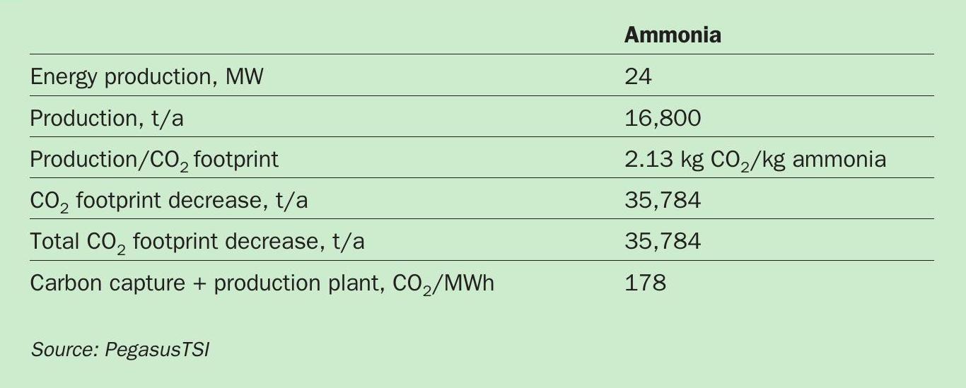
We have quantified the CO2 emissions and footprint benefits of producing green ammonia in a fertilizer industrial complex (Table 1). If the 24 MW of clean energy from the sulphuric acid plant were used for green ammonia production, we calculate that the CO2 footprint would be reduced by 35,784 t/a.
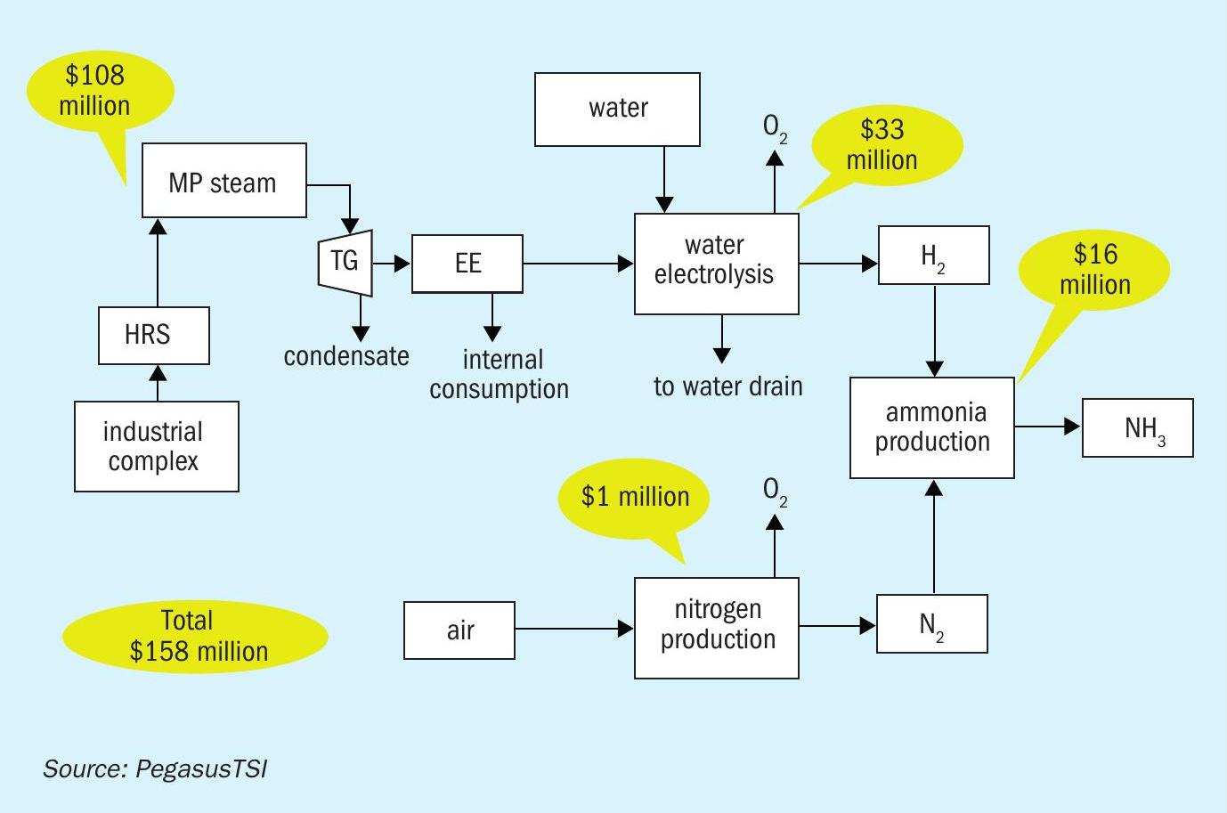
Green ammonia economics
We estimate a total investment of $158 million is required to produce 16,800 t/a of green ammonia. This capex amount covers:
- The two sulphuric acid plant heat recovery systems
- The steam turbine systems
- The electrolyser
- The ammonia plant.
- This cost breakdown is shown diagrammatically in Figure 3.
The economic feasibility of green ammonia production on this scale is based on the following parameters/assumptions:
- Investment: $158 million
- Green ammonia production: 16,800 t/a
- CO2 footprint decrease: 35,784 t/a
- Return on investment (ROI): 8%
Discussion and conclusions
Currently, green ammonia can be produced at a cost of around $900/t. That compares favourably to the current Tampa contract price of $1,625/t (start April), although this is at a historical high, having risen from $545/t twelve months ago. The demand for fertilizer products with a lower CO2 footprint is, in any case, likely to grow, independent of price competitiveness. The gradual conversion of existing ammonia plants to incorporate green hydrogen production, by lowering the capital investment barrier, could also improve adoption and project feasibility.
Technologies to decrease the CO2 footprint of fertilizer production are already commercially available. Their economic feasibility will, however, depend on the ability of the market to pay a premium for green ammonia. Our preliminary analysis, as outlined here, suggests that green ammonia production at an industrial fertilizer complex could be an attractive proposition when high CO2 emissions reduction is required at reduced capital investment.
The other option for increasing clean energy capacity and decreasing production costs, as part of a CO2 emissions reduction strategy, is to introduce renewable energy sources, like wind or solar, to supplement the clean energy generated by the sulphuric acid plant’s heat recovery system.
Author’s note
A longer version of this article was published in the March/April issue of our sister publication Sulphur magazine (Sulphur 399, p44). This also includes an analysis of the feasibility of green methanol production.
ELESSENT CLEAN TECHNOLOGIES
Options for delivering more green energy
Plant owners, neighbouring communities and environmental groups can all enjoy the green energy co-produced during the manufacture of sulphuric acid – thanks to the MECS® Heat Recovery System (HRS™ ). This technology has been enhancing the production of carbon-free energy throughout nearly 40 years of operation with over 100 units installed worldwide.
As the need for investment in green, carbon-free energy across the globe grows, MECS® HRS™ technology continues to improve and expand (Sulphur 396, p42). The production potential of various MECS® HRS™ steam generation technologies are summarised in Table 1.
MECS® HRS™
In the sulphuric acid process, the energy released through combustion and other exothermic reactions is easily recovered as high-pressure (HP) steam. In contrast, it is normally uneconomical to recover low-level energy – like the heat produced during SO3 hydration – and this is therefore dissipated at the cooling tower.
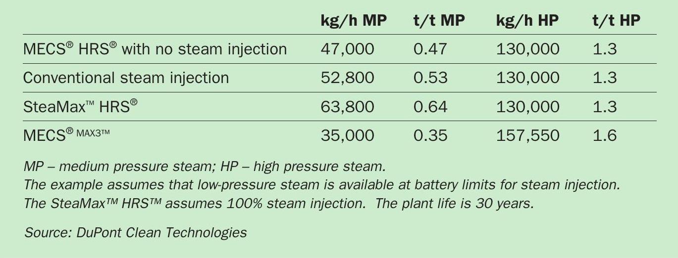
Yet with MECS® HRS™ technology, sulphuric acid plants can significantly increase their thermal efficiency by upgrading and recovering this low-level energy as medium-pressure (MP) steam (up to 150 psig (10 barg)). The amount of steam generated typically ranges from 0.4-0.6 tonnes of steam per tonne of acid produced, depending on the SO2 concentration and the water balance. Typically, this steam can then be used to produce three megawatts of electricity per 1,000 t/d of acid capacity.
In the MECS® HRS™ design, heat is removed in the HRS™ boiler, with water and low-pressure (LP) steam added into the process to control the acid concentration. By heating water in the HRS™ heater and preheater, the energy contained in the product acid can be captured and recovered. This energy transfer provides additional steam generation and reduces cooling water use in the plant as well.
MECS® SteaMax™ HRS™
MECS® SteaMax™ HRS™ exports more medium-pressure steam than a traditional MECS® HRS™ design. It increases medium-pressure steam generation by raising the ratio of dilution steam to dilution water. Low-pressure steam is added to the system for acid dilution. The energy in this low-pressure steam is then recovered as medium-pressure steam in the HRS™ boiler. This upgraded steam provides more value, as it offers plants greater flexibility in their steam use by allowing customisation to site-specific energy requirements and local conditions.
MECS® MAX3™
MECS® MAX3™ technology is the next stage in sulphuric acid plant energy upgrades – allowing up to 20 percent more high-pressure steam to be exported from the sulphuric acid plant. MAX3™ increases production of high value, high-pressure steam by employing a heat exchange networking system. This shifts a portion of the MECS® HRS™ energy – normally used to generate medium-pressure steam in the HRS™ boiler – to a high-pressure steam system instead.
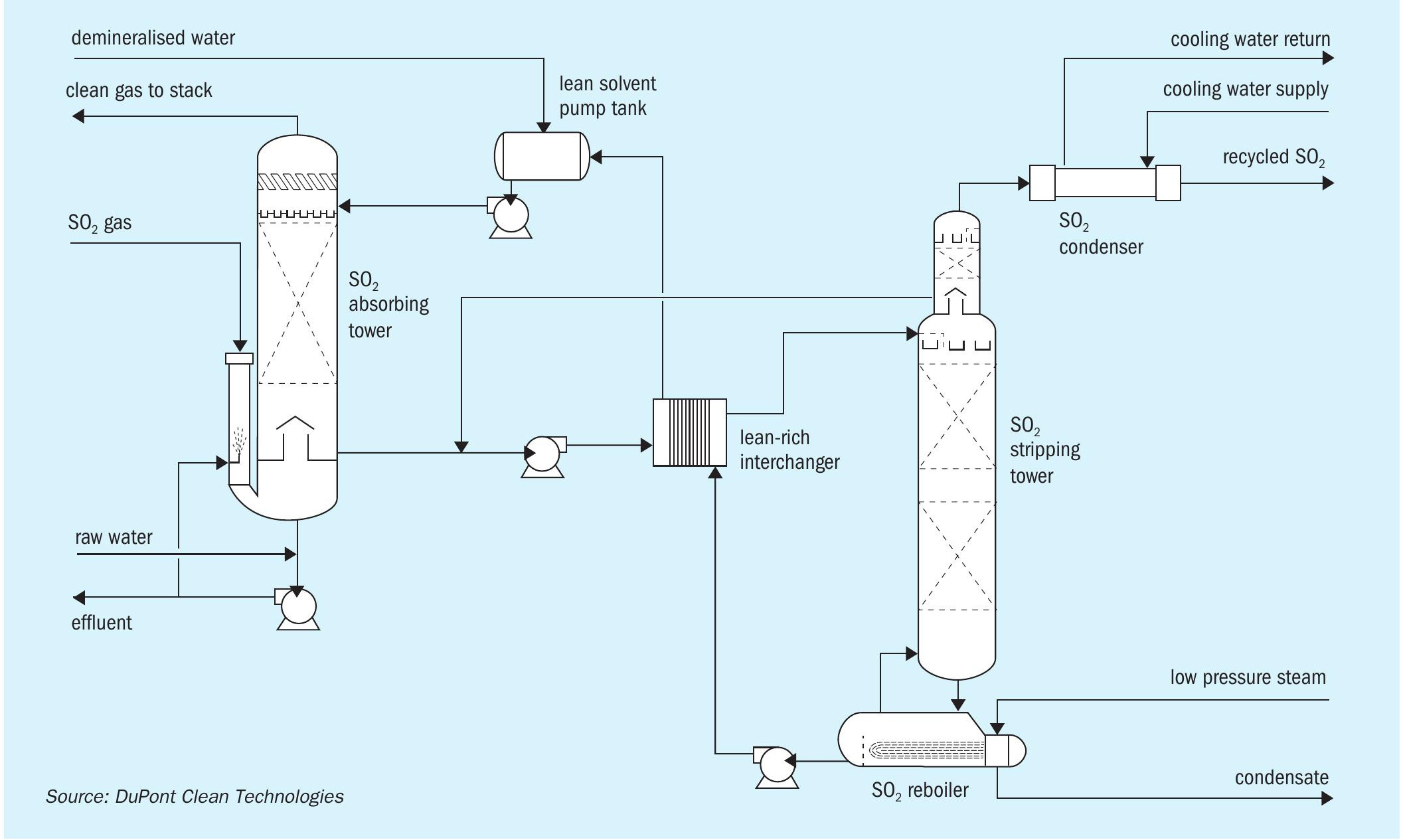
Notably, MECS® MAX3™ technology incorporates the SolvR® regenerative SO2 recovery system (Figure 1) – providing sulphuric acid plants with an ultra-low emission, high efficiency design, which is especially valuable for grassroots installations. This allows acid plants to produce high-quality acid, at or above nameplate capacity, while maintaining ultra-low greenhouse gas emissions. Additionally, the resulting low effluent rates minimise water losses. It is also a plant configuration that maximises carbon-free, green energy production, for either internal consumption or exported power sold to neighbouring sites.
Longevity and reliability
For sulphuric acid plant operators, energy efficiency and emissions reductions, while valuable, are only two on a long list of objectives. In a strong acid environment, for example, the longevity and reliability of equipment are also important considerations and cost factors. Beneficially, MECS® HRS™ and MAX3™ technologies can also satisfy these requirements, being designed with durability and low maintenance in mind, as the following case study illustrates:
A sixteen-year-old plant with MECS® HRS™ technology operating in China has consistently produced an on-stream time greater than 98 percent
Overall, downtime (including turnaround time) at this plant accounts for less than 2.5 percent of the overall cost of equipment replacement.
Combining equipment of known reliability with correct maintenance practices are key to a long plant life. State-of-the-art equipment such as Brink® AutoDrain™ mist eliminators and new catalysts can help to reduce overall maintenance costs and extend plant life.
In certain cases, adding new bolt-on systems at sulphuric acid plants can increase the amount of maintenance resources needed. Yet the other substantial benefits they provide – as discussed above – are very likely to far outweigh any incremental expenditure incurred over the life of the plant.