Sulphur 400 May-Jun 2022
31 May 2022
Design, safety and operational aspects of SRU analysers
SULPHUR PLANT PROCESS INSTRUMENTATION
Design, safety and operational aspects of SRU analysers
Jochen Geiger of AMETEK Process Instruments reviews SRU process analyser standards, how to choose the right instruments, what to watch out for when selecting the point of installation, responsibilities for the analysers after installation, and how to make best use of the information provided by these analysers. Potential upset conditions and how analysers can help us to understand and mitigate them are also discussed.
While all process control instruments are important, SRU analysers should be viewed as particularly important, and their reliability is paramount.
Not only is there virtually no back-up for these instruments, but there are also very limited “process back-up” options available.
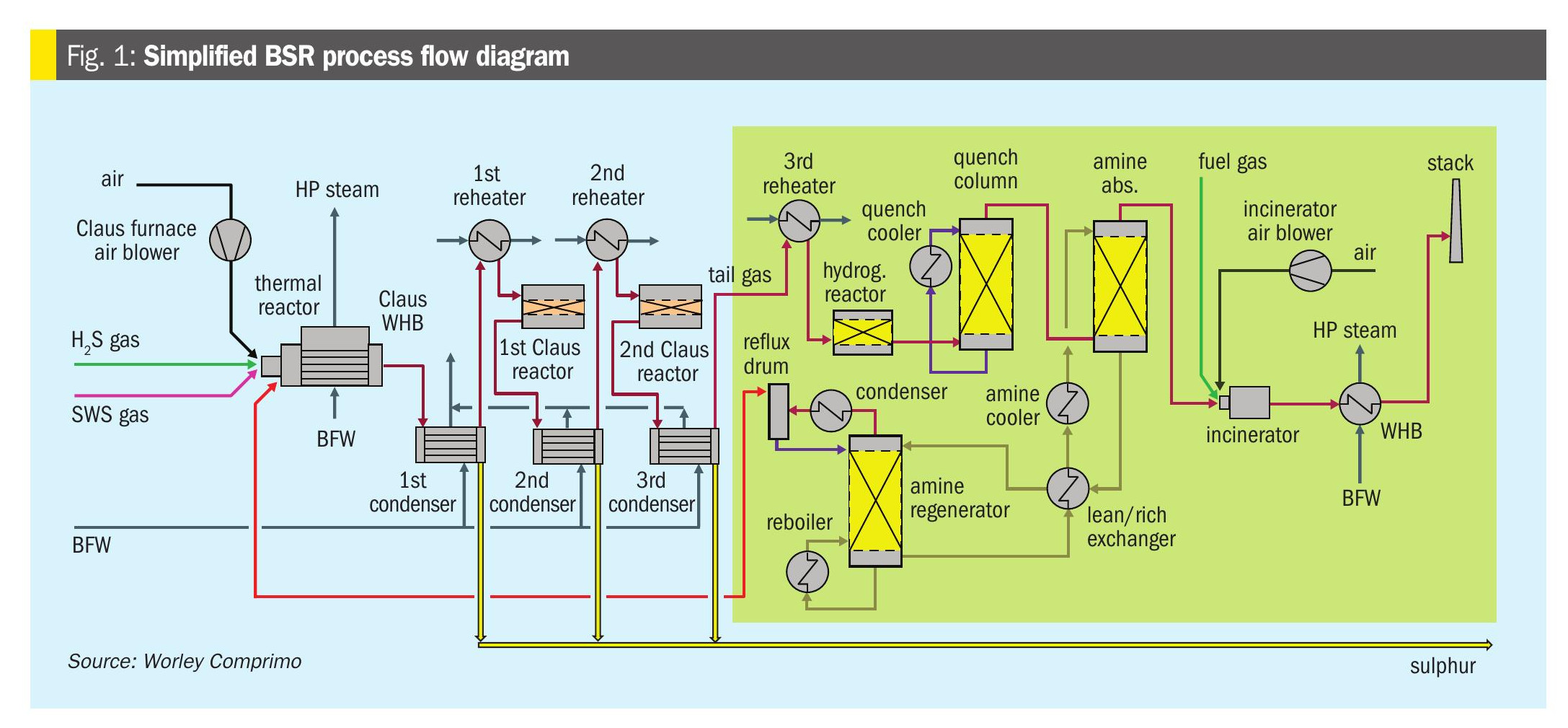
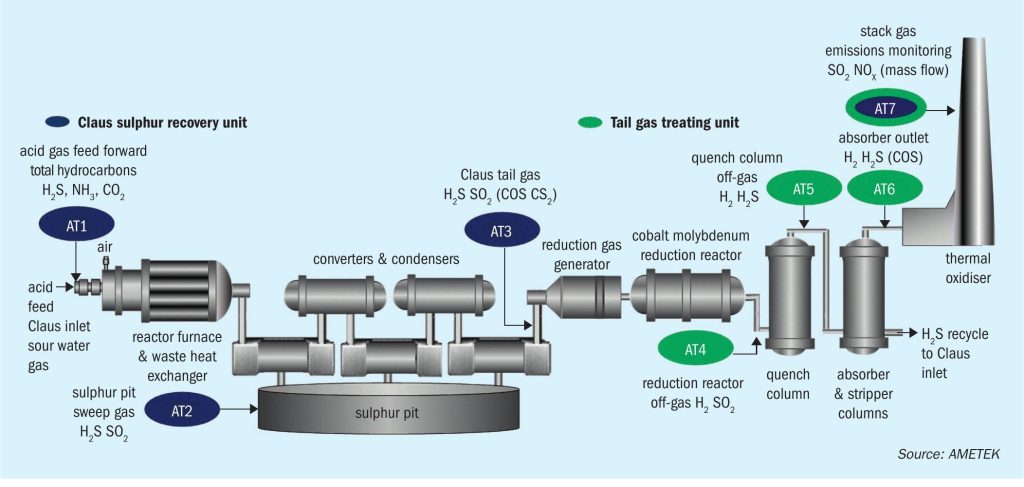
This article will discuss and review the design, safety, and operational aspects of SRU process analysers. Fig. 1 is a simplified process flow diagram of a Modified Claus process with tail gas treatment unit showing 7 analyser tags.
Step 1: Sample point selection
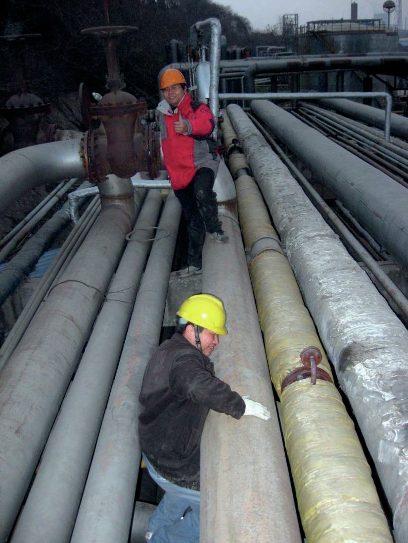
It is important is to choose the sample location as per the need of process control, but it is also important to take into account safety considerations. All measurements under review in this article are measuring a process gas which is toxic. Besides the question, “Is the instrument designed for this application?”, the sampling point should be easily accessible (Fig. 2). It is recommended to have mechanical design engineering, process piping, and instrumentation engineering review the sample point layout in a team effort.
Step 2: Instrument selection
After the location of the instruments has been finalised, the right analyser for the application needs to be chosen. The first question to ask is whether the instrument is suitable for this application and is it safe under all possible process conditions?
The second part of this article will focus on the specifics of each of the seven sample points.

Step 3: Installation and commissioning
Every process analyser installation consists of a sample take-off point (probes), sample transportation, the analyser itself and the infrastructure (shelter, platform etc.) From a cost perspective, roughly 30% of the total installation cost is analyser related and 70% of the cost is for the infrastructure, but more importantly, 70 to 80% of the total downtime of process analysers is related to failures in the sampling system and infrastructure such as heating, ventilation, and air conditioning (HVAC) units. It is therefore recommended to involve the instrument vendor and the maintenance group of the user in the installation planning/design process.
Step 4: Ownership and operational aspects
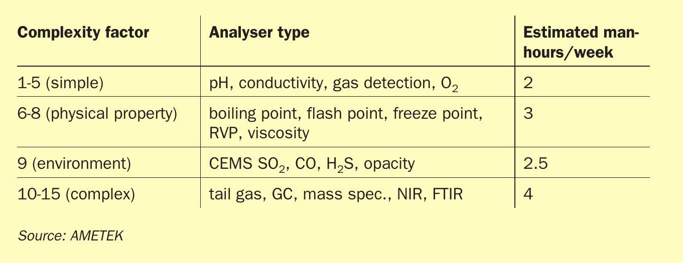
Any instrument requires service and maintenance, but how much? It very much depends on the application service and individual site conditions. It is recommended to create a “measurement matrix”. To begin with, all analytical instruments should be classified into different categories:
- Category A: Simple (such as the pH meter or gas detector)
- Category B: Liquide applications (such as physical property)
- Category C: Standard applications (such as emission monitoring or IR/ TDLS Instruments)
- Category D: Complex analysers (such as process gas chromatograph and SRU analysers).
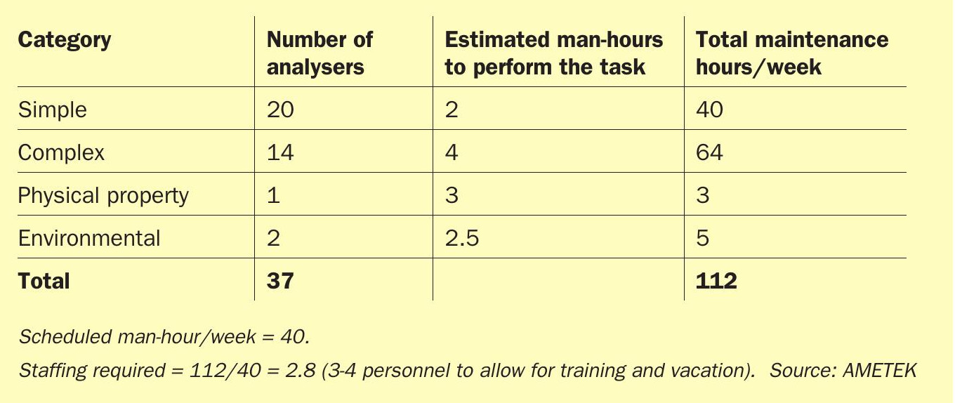
An hourly factor should be assigned to each of these categories, for example, four hours per week for Category D instruments and two hours for Category A instrument. Analyser vendors should be consulted to define the hourly factor. The rest is simple multiplication of instruments installed for each category; the result is a weekly estimated maintenance time demand sheet (see examples in Tables 1 and 2). The actual hours spent can then be compared to these theoretical numbers.
The outcome will provide a good base of information and help to identify root cause problems or help to understand if there is a requirement for technical training.
The next step to be considered is cross training between process engineers and maintenance engineers – it is not uncommon to hear, “These analyser readings cannot be correct, there must be something wrong today with the instrument!”
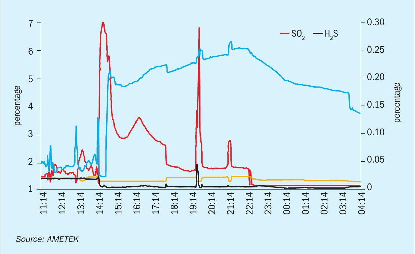
The following example is one of many; an air demand analyser suddenly moves to a full scale reading on the sulphur dioxide (SO2 ) output and a zero reading on the hydrogen sulphide (H2 S) output. What was the reaction from Process Control? The analyser is down/the analyser is not working! In fact, the true story behind the picture in Fig. 3 which shows the digital output of the analyser in question is that both measurements of this analyser were working fine, but there was a significant process upset condition. The amine circulation pump had failed so the SRU reactor was no longer receiving acid gas, only sour water stripper gas. Consequently, far too much air was being supplied to the reaction furnace which was being shown by the analyser reading. It has been observed in many such cases that the process control staff have limited knowledge about analyser readings, and, on the other hand, the maintenance staff have limited knowledge about the SRU process, resulting in misinterpretation and misunderstandings about the analyser behaviour.
One way to improve this is to have joint training classes with Process Control & Maintenance and Process Engineering in order to achieve a common basic understanding about the following points:
Claus process fundamentals
- basic Claus chemistry;
- a review of the capability of and limitations imposed on the process;
- the process vessels, reaction furnace, converters condensers;
- straight through, SWS burning and split flow reaction furnaces;
- tail gas treatment unit how it work what are the differences.
Sulphur plant process control analysers
- a review of the Claus chemistry as it pertains to control;
- feed forward control, advantages and limitations;
- feedback control, advantages and limitations;
- trim and main air control; l related instrument topics (furnace temperature, emission, feed gas analysis);
- tail gas treatment units and their impact on the Claus process control.
Understanding Claus process upsets using your tail gas analyser
- different case studies of Claus process upsets and their effect on the process. The studies concentrate on initial control response, tail gas analyser response and other confirming process indicators. Note this information is sometimes site specific and it is recommended that a process engineer be present so the relevant details for that particular SRU are accurate.
– delineating process upsets from analyser failure;
– verifying the analyser by “bumping” the process.
- analyser and sample system basics so process operators can aid the analyser technicians in trouble shooting problems.
- explaining the consequences of increased process temperatures, sulphur carryover and process upsets on the analyser.
All of these points will help to improve online instrumentation stability.
The following remarks refer to safety, design, and operational aspects for each of the sample/application points as shown in Fig. 1.
AT 1 – Feed gas analyser: to measure the acid feed and the sour water stripper gas: Most process engineers are interested in having this measurement as it sounds like a straightforward and simple task. However, the difficulty is the measurement has to be designed on a basically unknown process gas composition. The other factor is the measurement must be fast in terms of response time. Finally, it has to be considered that the sample gas can contain up to 90% H2 S, one of the most toxic gases in a refinery. So, whatever it takes, the measurement has to be designed in the safest way and should under no circumstances include a mechanical pump for sample transport. Safety as regards the sample system design, means keeping the sampling system simple. Something that is simple, easy to understand and operate eliminates “human errors”.
AT 2 – Sulphur pit sweep gas: This measurement is there for plant safety – higher H2 S concentrations can cause an explosion in the sulphur pit, the sulphur dioxide (SO2 ) measurement is there as an alarm for sulphur fires. From the design criteria the application has similarities to the air demand application.
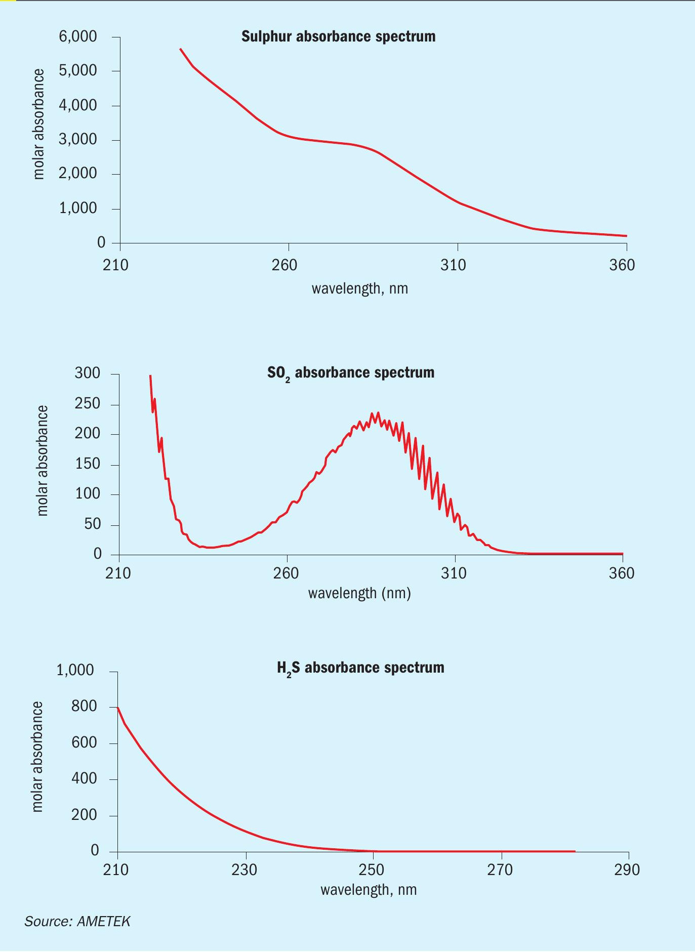
AT 3 – Air demand: the most common, widely used and often discussed application: The main task for the air demand/tail gas analyser is to provide reliable measurement of the hydrogen sulphide (H2 S measured at 228 nm) and sulphur dioxide (SO2 measured at 280 nm) concentration. The challenge is shown in the pictures in Fig. 4.
The process gas also contains elemental sulphur in vapour or aerosol form and has strong absorption of ultraviolet (UV) energy in the same spectral region as the measurement of the two components of interest.
AT 4 – Reduction reactor off gas: This is a low-level sulphur dioxide measurement. What makes this application difficult is that the sample is hot and wet, plus the H2 S concentration is high (safety aspects) and the usual reading of the analyser is around zero, so there are trust issues when there is a sudden increase.
AT 5 – Quench tower outlet: This H2 measurement is used as a standard but the additional measurement of H2 S should also be taken into consideration. Both measurements can be taken using a single instrument. The other use of the H2 S reading is during a plant shutdown – only when the H2 S is reading zero can you be sure that there is no elemental sulphur left in the Modified Claus unit.
AT 6 – Absorber outlet: The H2 measurement is standard but the additional measurement of H2 will provide the recommended redundancy. In addition, COS and CS2 can be measured by the same instrument.
Consider the combination of AT 5 and AT 6. First, a redundant measurement of H2 will make the entire process control safer. Second, if H2 S is measured at the quench tower outlet and the absorber outlet it will be possible to control and measure the efficiency of the absorber online, on a 24/7 basis. A question for the future will be the energy consumption of the amine regenerator; an on-line efficiency measurement of the absorber can potentially reduce the energy put into the regeneration process and help to reduce the overall emission of carbon dioxide (CO2 ). Plus, closer control of the flowrate of recycled amine is becoming possible based on the H2 S IN and OUT measurement.
The COS and CS2 measurement will provide information about the “status” of the catalyst in the reducing reactor.
AT 7 – Stack analyser: the final point of the SRU process control. Besides the emission monitoring aspects usually discussed in relation to this measurement, this can be also regarded as the final plant control analyser.
When the SO2 is measured correctly, i.e., hot/wet without any dilution systems, the reading can be considered as the overall efficiency measurement, comparing the H2 S entering the reaction chamber vs. the SO2 mass emission.
Another critical design aspect has to be considered if the SRU train includes a tail gas treatment unit (TGTU) which might be bypassed under process upset conditions. In such cases, the SO2 concentration can be significantly higher than normal (factor 20+).
Conclusion
Sulphur recovery unit process analysers are essential for process control and operating within the environmental limits as required by law. In order to guarantee the best possible overall performance of such analysers the selection and thinking process need to start during the very early stage of the design phase (sample point location). Process and instrumentation engineers should be consulted at each step of the instrumentation selection phase. Guidance should be obtained from instrument vendors and safety aspects should be thoroughly considered. Maintenance and training should be regarded as essential for the smooth performance of the instruments over the instrument lifetime.
Beside a proven industrial track record, potential instrument (analyser) vendors should offer:
- support during the bidding phase of projects, data sheet review, installation and piping review;
- planning and design of tailor-made turnkey analyser packages;
- supervision and commissioning support;
- start-up services;
- side service training;
- SRU training covering chemical – hardware and operational topics.