Nitrogen+Syngas 377 May-Jun 2022
31 May 2022
Highly optimised ammonia synthesis catalysts
AMMONIA CATALYSTS
Highly optimised ammonia synthesis catalysts
Ammonia synthesis catalysts have seen major improvements over the last 100 years, and they are highly optimised with respect to activity, thermal stability, and poisoning resistance. Improving such catalysts even further requires a deep understanding of their structure and the impact of different parameters on performance. Clariant, Johnson Matthey and Topsoe report on their studies and developments in ammonia synthesis catalysts.
CLARIANT
AmoMax® 10 Plus: From fundamental understanding to industrial application
Ammonia synthesis is one of the oldest catalytic reactions carried out on a large scale, and a tremendous amount of research effort has been put into catalyst optimisation over the last 100 years. The most common strategy for catalyst optimisation utilises incremental improvements based on empirical studies, e.g., high throughput preparation and testing. Although this approach has led to considerable improvements, its limitations are evident. As a leading catalyst manufacturer, Clariant believes that a deep understanding of the catalyst structure and underlying mechanisms are crucial, to allow thinking outside of the box and to surpass the limitations of purely empirical research. Clariant’s approach follows a rational catalyst design based on a deep understanding of its structure and how different parameters impact the catalytic performance. In order to study the catalyst behaviour under realistic operating conditions, an in-situ catalyst characterisation at high pressure and temperature is necessary. Such studies require highly sophisticated equipment and expertise. Clariant has partnered up with two Max Planck institutes, CEC and FHI, to study the relationship between composition, structure, and performance of iron oxide catalysts in context of the reduction mechanism. Applying the learnings from these studies, a new catalyst that provides unprecedented performance benefits was designed: AmoMax® 10 Plus.
Characterisation of model catalysts
Ammonia synthesis catalysts are commonly based on iron oxides, i.e., magnetite (Fe3 O4 ) or wüstite (Fe1-x O). The catalytically active species α-Fe is produced by reducing the iron oxide precursor inside the converter. Thus, to optimise the catalyst’s structural properties, it is crucial to understand the reduction mechanism. Compared to magnetite, wüstite-based catalysts contain less oxygen, making them easier to reduce.
In order to study the reduction mechanism in detail, three different wustite-based model catalysts were prepared:
- Pure Fe1-x O
- Fe1-x O promoted with K2 O and Al2 O3
- Fe1-x O promoted with K2 O, Al2 O3 , and CaO
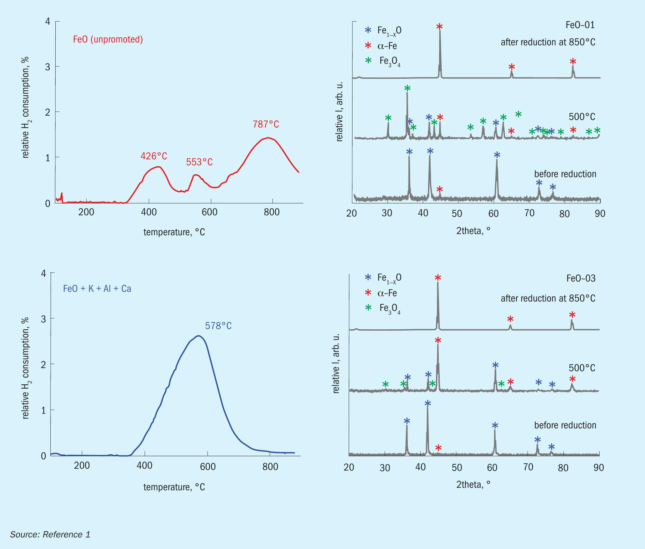
Temperature-programmed reduction (TPR) was performed on these catalysts and an industrial wustite-based catalyst. In addition, the catalysts were studied by X-ray diffraction (XRD) before and after reduction at different temperatures. The results for two of the model catalysts are illustrated in Fig. 1.
The results show that the reduction behaviour strongly depends on the promoter composition: While the unpromoted catalyst shows three distinct reduction peaks, the promoted catalyst shows only one large reduction peak. XRD shows large amounts of magnetite in the unpromoted catalyst after partial reduction at 500°C, while very little magnetite is found after partial reduction of promoted wüstite.
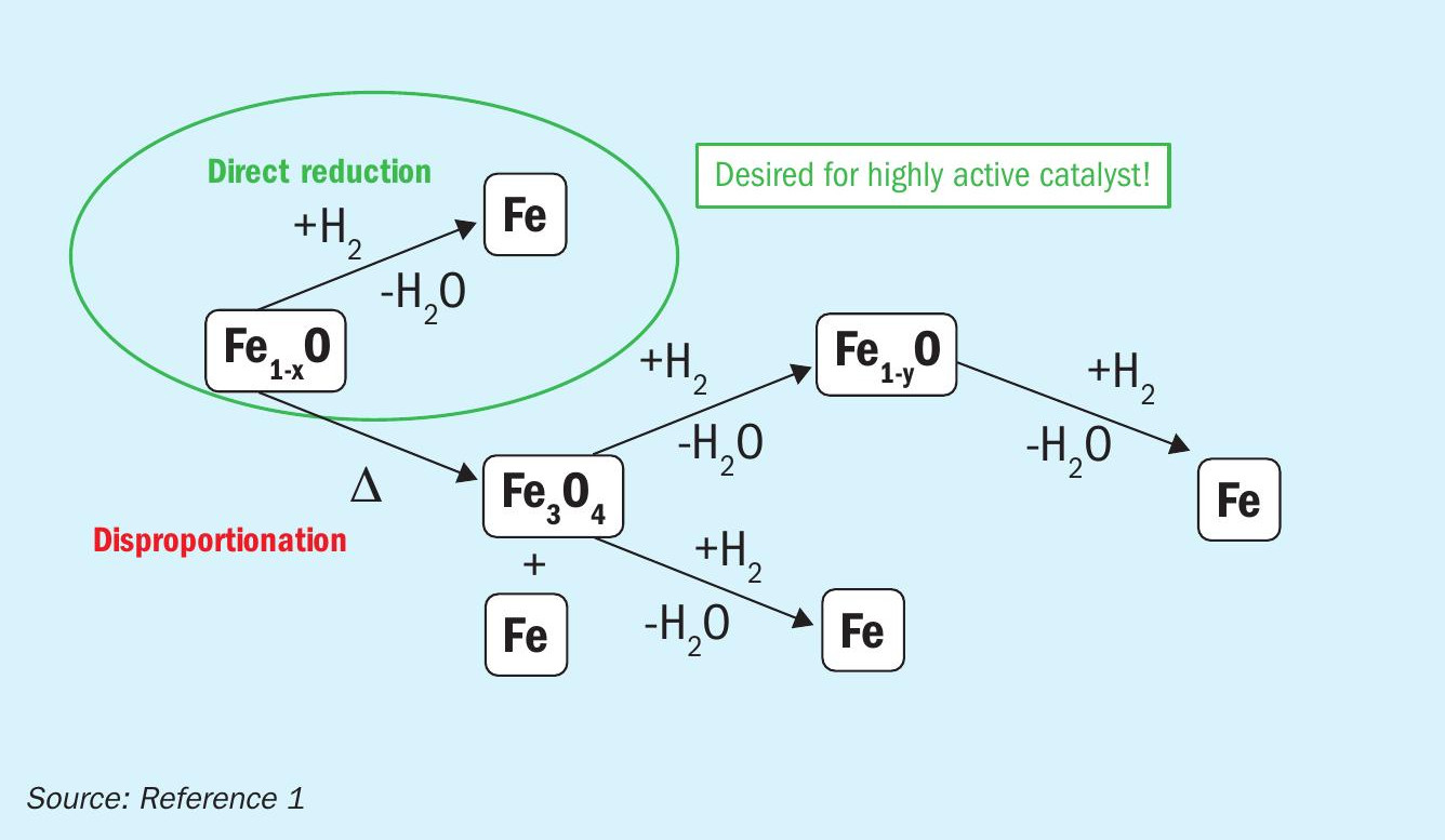
Based on these results, a reduction mechanism is proposed (Fig. 2): Wüstite can either be reduced directly to iron or disproportionate to magnetite and iron. The magnetite phase generated by thermal disproportionation is then reduced to iron, either directly or via intermediate reduction to wüstite. While disproportionation leads to large, catalytically inactive bulk iron, direct reduction results in high surface nanoplatelets, a prerequisite for high catalytic activity. Certain promoters stabilise the metastable wüstite, thereby preventing disproportionation.
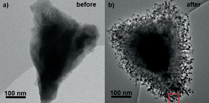
The pressure during reduction has a significant impact on the catalyst’s microstructure. However, in-situ studies are commonly performed at low pressure. In order to bridge this “pressure gap”, a sophisticated experimental setup for high-pressure quasi in-situ transmission electron microscopy (quasi in-situ TEM) was developed at FHI. Consequently, quasi in-situ TEM experiments were performed on the triply promoted wüstite catalyst in order to study the structural changes during reduction under high-pressure conditions (10 bar). Fig. 3 shows the same particle before reduction (left) and after partial reduction at 365°C (right). After partial reduction, the wüstite core is surrounded by a porous layer of nano-sized iron platelets. In addition, some magnetite is found. These observations corroborate the proposed reduction mechanism, where even with the promoted system, small amounts of magnetite are formed during the early stages of reduction due to the disproportionation of wüstite.
When designing a catalyst, it is important to understand the correlation between structure and performance. To shed light on these correlations, the catalytic performance was tested at 90 bar and 400°C in a fixed bed lab-scale reactor. In addition, the BET surface area and pore volume of the spent samples were measured by N2 physisorption. The results are summarised in Fig. 4.
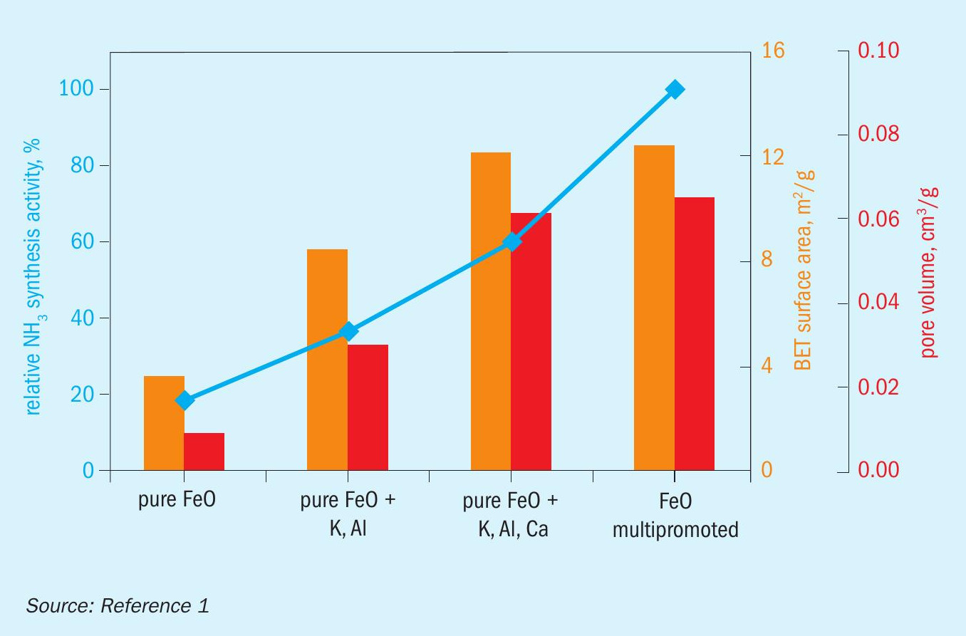
A clear correlation was observed between BET surface area, pore-volume, and catalytic activity for unpromoted wüstite doubly promoted wüstite, and triply promoted wüstite: With increasing surface area and pore volume, the catalytic activity increases. These observations further corroborate the proposed reduction mechanism: The chosen promoters stabilise wüstite, inhibiting the disproportionation and favouring direct wüstite reduction, which leads to the formation of iron nanoplatelets. These platelets provide a high surface area, which is correlated with high catalytic activity. Interestingly, the multi-promoted industrial wüstite catalyst is considerably more active than the triply promoted model catalyst, but it does not have a significantly higher surface area or pore volume. This indicates that there are other effects of promoters that are not related to generating and maintaining a high surface area. Such effects can include an electronic promotion or the generation of specific crystallographic defects.
In summary, a strategy can be formulated that allows a highly active wüstite catalyst to be generated based on the proposed reduction mechanism: The catalyst must be designed to favour direct reduction over disproportionation, thereby creating highsurface-area iron nanoplatelets (Fig. 5).

Development of AmoMax® 10 Plus
Design approach
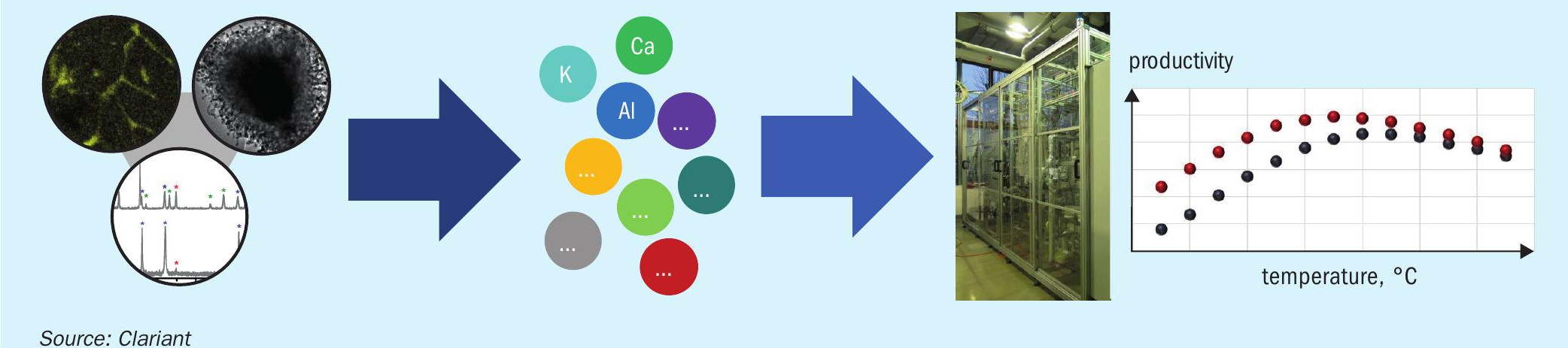
The last section has provided some insights into the investigations to understand the correlations between catalyst composition, microscopic structure, and performance parameters. Equipped with these learnings, it is possible to design a catalyst by adjusting the recipe for optimised performance. Applying this rationale design approach as illustrated in Fig. 6, Clariant optimised the composition of AmoMax® 10, a highly active catalyst with more than 100 references around the world, to obtain a next-generation catalyst with unprecedented performance: AmoMax® 10 Plus.
One of the main advantages of wüstite-based catalysts compared to classical magnetite-based catalysts is that they are more easily reduced while releasing a lower amount of water due to their lower oxygen content. This is already the case with Clariant’s current generation wüstite catalyst, AmoMax® 10, Fig. 7 shows that AmoMax® 10 Plus is even more easily reduced, with a roughly 10°C lower reduction temperature compared to
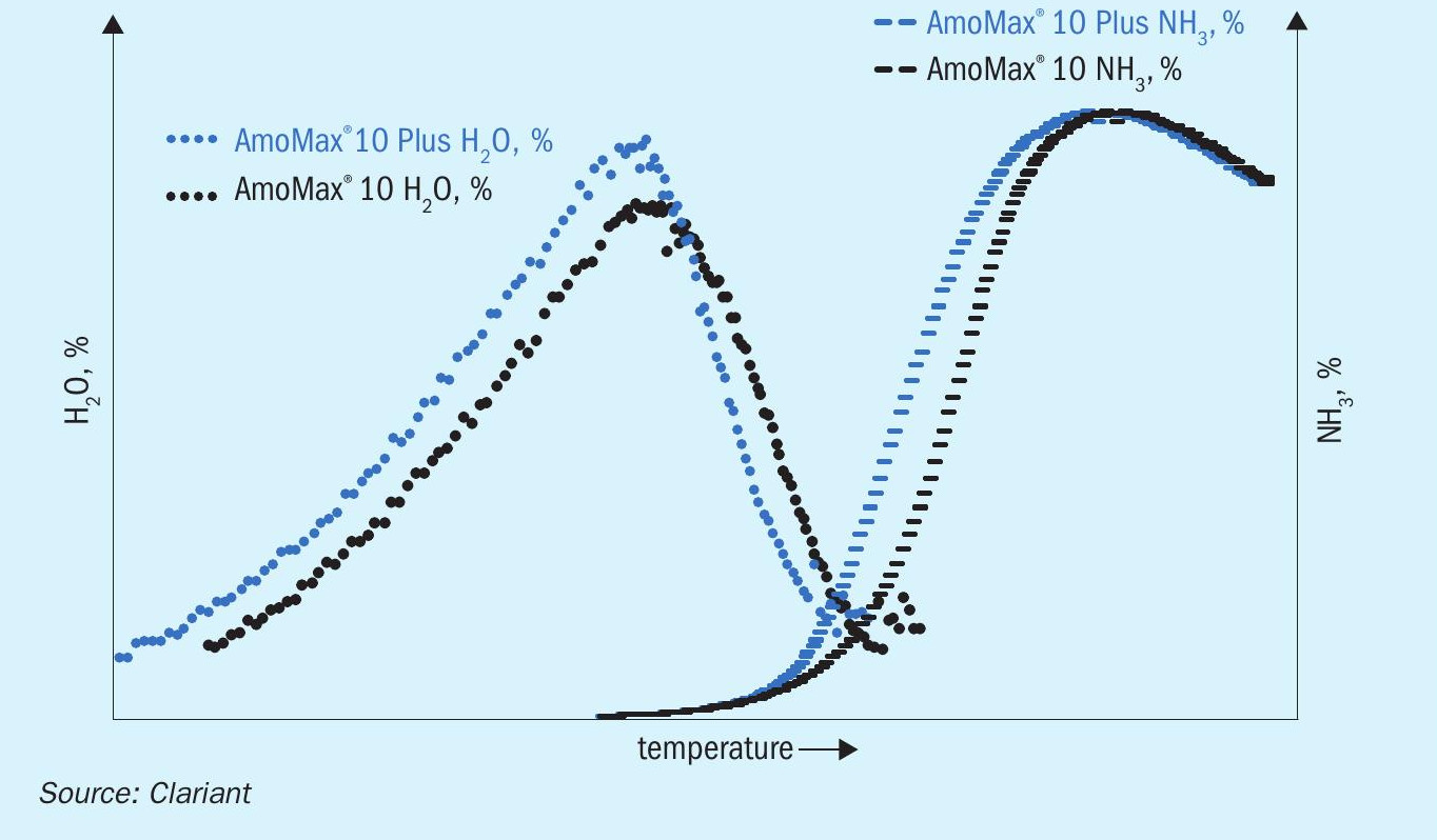
AmoMax® 10 at 90 bar. This faster reduction leads to a lower light-off temperature due to an earlier onset of NH3 production. A faster reduction and lower light-off temperature are highly beneficial because they can save considerable time during start-up.
Catalytic performance
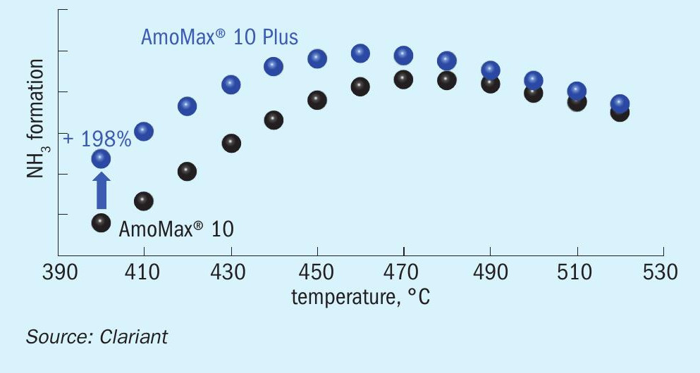
A crucial performance parameter for ammonia synthesis catalysts is their resistance to poisoning, particularly by oxygenates such as H2 O, O2 , CO, and CO2 . The most common poison is H2 O, which is released during catalyst reduction but can also be present in small concentrations (usually below 10 ppm) in the feed gas. In addition, the catalyst may be exposed to high water concentrations during certain unexpected events. It is not uncommon that one or more of these events occur over the catalyst lifetime of 15+ years. The water resistance during NH3 synthesis was tested in a bench-scale reactor by dosing 80 ppm water into the feed gas at a pressure of 100 bar. Fig. 8 shows the performance of AmoMax® 10 and AmoMax® 10 Plus under these conditions. Clearly, AmoMax® 10 Plus is considerably more active under poisoning conditions, especially at low temperature where the poisoning effect of water is typically the strongest. At 400°C, AmoMax® 10 Plus provides a productivity boost of nearly 200%.
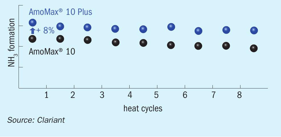
Due to the high expected lifetime of 15+ years, stable long-term performance is a crucial feature of an ammonia synthesis catalyst. Therefore, rapid aging tests were performed in order to study the long-term thermal deactivation of the catalyst. After each heat cycle (520°C, 150 bar), the NH3 productivity was measured at 400°C and 100 bar. The performance over eight heat cycles is illustrated in Fig. 9. Both AmoMax® 10 and AmoMax® 10 Plus exhibit very high thermal stability, but AmoMax® 10 Plus is roughly 8% more active overall.
Value creation
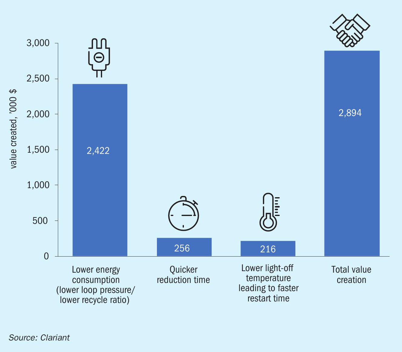
The higher activity of AmoMax® 10 Plus enables a lower loop pressure and a lower recycle ratio, which results in considerable energy savings. The expected savings compared to a benchmark magnetite catalyst were calculated for a typical 1,600 t/d ammonia plant over a lifetime of 15 years, assuming natural gas costs of $4.0/million Btu and an ammonia price of $220/t (Fig. 10). Most of the total savings are due to lower energy consumption, which is estimated to be 0.15 GJ/t of ammonia. The easier reduction and lower light-off temperature are expected to generate the additional value of nearly $0.5 million. All in all, the expected value creation over 15 years adds up to nearly $3 million.
Acknowledgments
We acknowledge Prof. Robert Schlögl, the Max Planck Institute for Chemical Energy Conversion (CEC), and the Fritz Haber Institute of the Max Planck Society (FHI) for their crucial contributions that helped elucidate the reduction mechanism of wüstite-based ammonia synthesis catalysts.
Reference
JOHNSON MATTHEY
High activity ammonia synthesis catalyst and its role in the transition to a low carbon economy
There is an increasing focus internationally on reducing greenhouse gas (GHG) emissions to limit the effects of global warming, resulting in the introduction of ever more stringent emissions limits and the rapid development of new low carbon technologies. In countries with emissions trading schemes there is an extra incentive to reduce the carbon footprint of plants, especially in Europe where carbon prices have risen considerably in early 2022. The high gas prices currently being seen in some regions are also an effective driver to increase plant efficiency in order to drive down opex costs. For new plant designs the focus in green and blue ammonia flowsheets as an effective way of addressing these issues and these technologies are key to achieving GHG reduction targets, whereas for existing conventional plants the change will be more gradual, with revamps or replacement over time to low carbon alternatives.
Away from the established markets for ammonia in fertilizers and chemical production, which will continue to grow, there is also projected to be a large emerging market for ammonia as a hydrogen transport vector. A lot of investment is rightly going into green hydrogen production as a source of fuel, but hydrogen itself is not the best choice as an energy vector, having a low energy density and being difficult to store and transport. Due to this, the feasibility of using other compounds as hydrogen transport vectors has become a topic of discussion. Ammonia is currently considered a front-runner as a hydrogen transport vector due to a high hydrogen density (120 kg H2 per m3 at -33°C, 1 atm)1 and existing infrastructure for storage and transportation associated with the mature fertilizer and chemicals industry. Ammonia can also be used as a fuel itself, either as pure ammonia or partially decomposed ammonia along with the option to fully decompose to hydrogen for use in fuel cells or energy generation. Plants to service this market will be blue or green ammonia designs and are projected to make up the majority of the new ammonia plants being built in the mid to long term.
High activity ammonia synthesis catalysts can be effectively utilised in all of these scenarios to optimise synthesis loop operation. For existing plants, either as a standalone catalyst replacement or as part of a wider revamp, utilising a high activity ammonia synthesis catalyst over a standard one enables loop operation at the most efficient conditions and can thereby reduce the comparative consumption of the plant. In new blue ammonia plants, where the catalytic stages operate at similar conditions to conventional grey ammonia plants, the same benefits can be realised by incorporating the high activity synthesis catalysts at the design stage. For green ammonia plants the number of catalytic stages is limited as electrolysers are used to generate hydrogen rather than conventional steam methane reforming and water gas shift, but Johnson Matthey has solutions for both the deoxygenation stage and the ammonia synthesis stage at the full range of operating pressures for projects currently being developed.
The catalyst
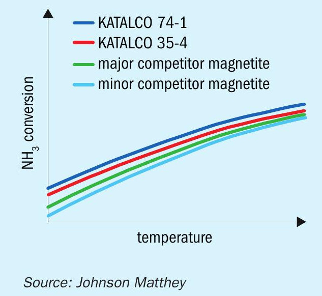
KATALCO™ 74 series catalysts were initially developed for used in the AMV and LCA processes, which required the highest activity catalyst for their low pressure (80 bar) synthesis. As this increased activity compared to conventional magnetite catalysts is applicable over the whole range of ammonia synthesis converter pressures however, more recently it has been adopted for high pressure synthesis loops. This increase in activity, illustrated in Fig. 1, and an increased ease of reduction are achieved by incorporation of cobalt oxide as a promotor and differing, re-optimised levels of the other structural and electronic promotors compared to standard magnetite catalysts. The cobalt has the effect of increasing the rates of nitrogen adsorption and ammonia desorption from the surface of the catalyst, hence increasing the rate of the overall synthesis reaction.
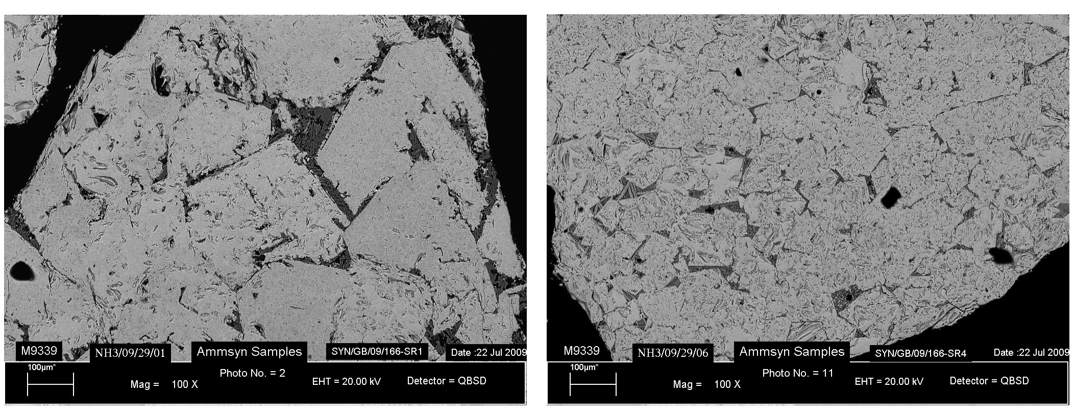
A number of studies2-5 into the location of cobalt in ammonia synthesis catalysts have looked at the reasons for the positive effect on catalyst reduction and activity. In these studies, cobalt oxide is found as a solid solution dissolved in the magnetite phase. The incorporation of cobalt into the iron lattice distorts the structure of the fused iron catalyst, generating layers of cobalt spinels which typically produce smaller iron crystallites on reduction, as shown in Fig. 2. This is a significant factor in generating the high activity of the material.
This catalyst is robust and stable, with the high activities relative to conventional magnetite catalysts sustained over long catalyst lifetimes. Johnson Matthey has a long list of references for these KATALCO 74 series catalysts, all showing high activities maintained for long lifetimes with a number of plants operating for over 20 years on the same charge.
Existing plants
The optimal operation of a synthesis loop and its corresponding plant is dependent on a number of factors. Plants located in areas with a cheap supply of natural gas will often want to prioritise increasing ammonia make over the efficiency of the plant, although the shift to focus more on plant emissions may shift these operators to focus more on plant efficiencies and the reduction of emissions. Plants with more expensive feedstocks and in areas with more stringent regulations on emissions and in carbon trading schemes will tend to want to focus on maximising the efficiency of the plant, which is what this article will focus on.
Increasing efficiency and reducing the energy consumption of the synthesis loop is a balancing act, trying to minimise the cumulative requirements of compression, refrigeration, and recirculation. As the loop pressure increases the compression duty goes up, but the refrigeration duty decreases and as the reaction equilibrium is more favourable more ammonia is produced over the converter and the recycle rate and hence recirculation duty also drops. The reverse is also true and when the operating pressure deviates too much from the optimal position in either direction the overall energy consumption rises substantially, so to maximise efficiency the aim is to operate close to this pressure for minimum energy consumption. However, this minimum will differ from plant to plant – depending on the design and age of the plant, the compressor design and how it is driven, whether there have been any retrofits and even the age and performance of installed catalysts in the front end can have an impact.
Case study 1
A modern 2,200 t/d thyssenkrupp Industrial Solutions (tkIS) plant has a three-bed design using two converters with an HP steam boiler in between bed 2 and bed 3. By using KATALCO 74-1 instead of KATALCO 35-4 in the design the loop pressure can be reduced by 4% while maintaining the same production rate, efficiently saving compression energy and reducing the overall consumption of the plant, along with its associated emissions. This plant has now been up and running for five years and is performing well, with previous data sets showing an exit ammonia concentration of above 22%, well above the required performance at a loop pressure of 192 barg – 15 bar below the flowsheet pressure and enabling them to produce significantly more than the nameplate production rate whilst still operating efficiently.
Case study 2
High activity catalysts are most beneficial when installed in beds with difficult duties – for example, high inlet ammonia, lower hydrogen and nitrogen partial pressures. In some plants it may be beneficial to target these particular beds for replacement with high activity catalyst rather than replacing the whole quota of beds. A retrofit of a converter on a European plant reinforces this – the first bed is installed with a KATALCO 35 series catalyst, as the duty is relatively easy, but as the reaction becomes more inhibited and the bed temperatures need to be lower the high activity KATALCO 74 series catalyst is used in the second and third beds to maximise the reaction rate. This configuration, along with the changes to the converter internals, has allowed the plant to gain a significant benefit with respect to the pressure the loop must operate at to meet production requirements. At the end of the previous charges’ lifetime the converter inlet pressure was >300 barg and it was achieving an outlet ammonia concentration of just under 16%, the new charge with KATALCO 74 series catalyst in beds 2 and 3 and new internals achieved an outlet concentration of 22% at <230 barg, far greater conversion at a substantially lower pressure. This reduction brings the pressure down close to that minimum in terms of loop power consumption, substantially increasing the efficiency of the back end of the plant.
Revamps
The scope for low carbon solutions via revamps is dependent on the final product manufactured on the site – if the ammonia is fed to a urea plant, then the majority of the carbon dioxide recovered in the CO2 removal stage will be used as feedstock for urea production. In this case there is potential for carbon capture and storage (CCS) only from the flue gas exit the primary reformer and any surplus CO2 not required for urea production. If the plant is producing merchant ammonia or the site is manufacturing ammonium nitrate, etc. then more of the carbon can be captured and sequestered with potential CCS on both the flue gas from the primary reformer and the CO2 stream from the CO2 removal stage. Concurrently with installing CCS technology many plants will look to make other improvements during a revamp project including debottlenecking and opex reductions, where a high activity ammonia synthesis catalyst such as KATALCO 74-1 can be utilised in conjunction with other upgrades to get the most out of the plant.
Clean ammonia production
Blue ammonia
Blue ammonia will be a key technology in the drive to low carbon ammonia and energy, whilst carbon dioxide is still produced by the process, it is produced in a form which can be captured and sequestered. This technology is closer to a conventional “grey” ammonia plant and as such in the short term is more viable for the bulk of the large-scale new ammonia plants, whereas green ammonia technology at this scale will likely become more prominent in the mid to long term. As the major differences between existing “grey” ammonia plants and blue ammonia flowsheets are around the reforming section, the conditions within the synthesis loop will be within the bounds of currently operating plants. Both KATALCO 35 series and the high activity KATALCO 74 series catalysts have proven strong performance at these conditions – in particular the KATALCO 74 series catalysts can be used to maximise activity within the ammonia synthesis reactor and optimise loop performance.
Green ammonia
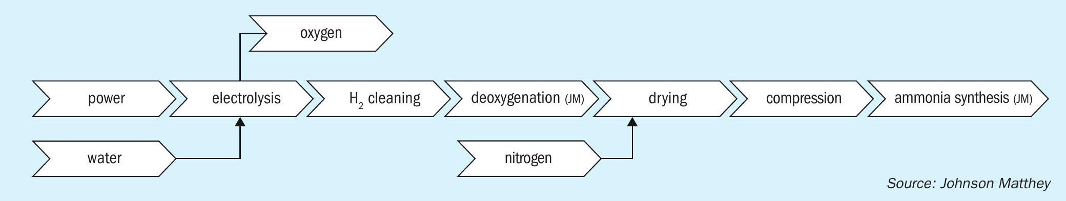
With improved electrolyser technology, falling renewable energy costs, and the drive to reduce carbon emissions, green ammonia is looking increasingly favourable as a viable alternative to SMR based production. The majority of projects in development are based on updated AWE or PEM (proton exchange membrane) type electrolysers, with a general configuration similar to that shown in Fig. 3, a process schematic showing the building blocks of a typical green ammonia process.
One of the big considerations for these plants is how best to match the input power to the desired ammonia production rates. To effectively decarbonise the system the power generated must come from renewable or decarbonised energy production, but most renewable energy production methods have large fluctuations in output, for example wind and solar energy both fluctuate greatly depending on the weather. There are various methods in development to mitigate these effects, but despite this there will be more fluctuation in the flow of syngas to the synthesis loop compared to a conventional “grey” ammonia plant, so this will need to be factored into the design of the equipment in the loop to ensure that it is robust and adaptable to these conditions.
The green ammonia technologies in development fall into two major categories – designs with high pressure synthesis loops and those that have low pressure ammonia synthesis at the electrolyser operating pressure. The low pressure plants tend to be at a smaller scale or modular in design, with multiple modules to achieve the desired capacity. The high pressure plants may also have a modular approach in terms of the electrolysis section, with the potential to add more capacity over time but they have a large ammonia synthesis loop operating at high pressures (from 130 to over 300 barg). Some of the projects focussing on the smaller/modular plants are designing for ammonia production at the operating pressure of the PEM electrolyser to reduce the need for compression. These projects are looking at ammonia synthesis at significantly lower pressures than existing large-scale ammonia production, from some as low as 20 barg to around 45 barg, with relatively low conversion per pass of ammonia in the synthesis reactor due to the less favourable equilibrium conditions.
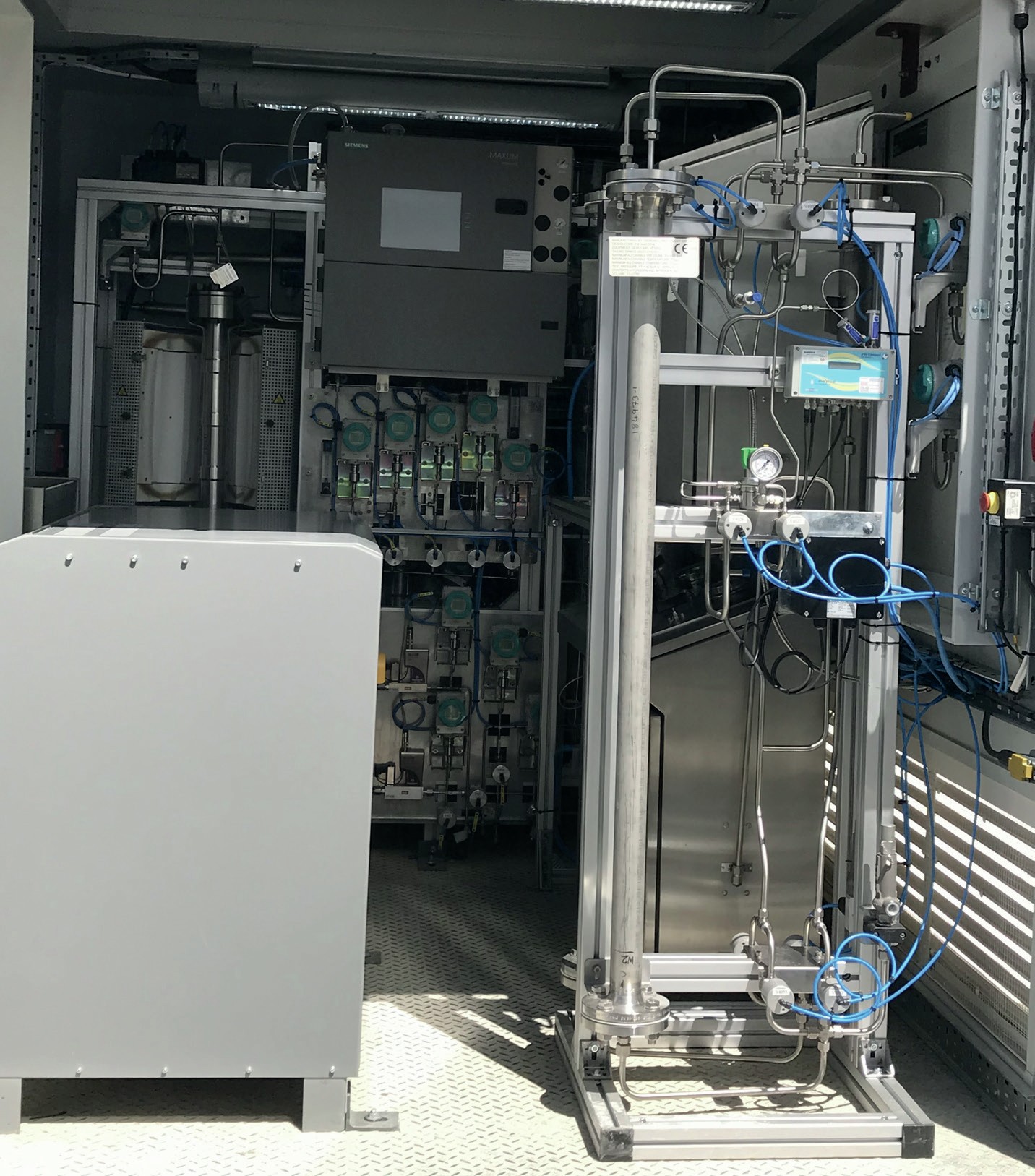
For the high synthesis pressure type designs the conditions within the loop are similar to conventional ammonia plants or with even higher pressures so the reaction equilibrium is relatively good and conventional catalysts are suitable for this duty, with KATALCO 74-1 GREEN a superior choice to deliver high performance in the centralised synthesis loops. In the UK as part of National Net-Zero Project a Green Ammonia Demonstrator (Fig. 4) was designed, built, and commissioned at the Science & Technology Facilities Council (STFC) Rutherford Appleton Laboratory in Oxfordshire in 2018. This unit was loaded with JM’s high activity KATALCO 74-1 GREEN ammonia synthesis catalyst. The aim of the project was to be a small-scale demonstrator for the world’s first roundtrip application of green ammonia for energy storage Powerto-Ammonia-to-Power (P2A2P). The project was part of the Siemens-led Decoupled Green Energy project and is now entirely operated by STFC.
To assess the viability of ammonia synthesis at the low pressures associated with the small, modular green ammonia units in development, testing of KATALCO 74-1 GREEN catalyst was undertaken down to pressures of 25 barg. This testing and associated modelling confirmed that KATALCO 74-1 GREEN still shows high activity at these low pressures and Johnson Matthey’s in-house models provide a good measure of the reaction dynamics even in this operating envelope. Due to the low pressures the equilibrium conversion is significantly lower than in conventional ammonia synthesis reactors so the outlet ammonia concentration from the reactor is lower (likely <10 mol-% NH3 ) and a higher recycle rate would be necessary compared to the higher pressure loops.
Summary
Ammonia production continues to be of utmost importance internationally, both in its existing markets of fertilizer and chemicals production and the emerging market of green ammonia as a hydrogen vector and fuel. For existing production facilities the challenge is to expand production sustainably whilst reducing plant emissions and requires a focus on operating efficiency, achieved through revamps (including carbon capture and storage) and the use of high performance catalysts such as KATALCO 74-1 to optimise this efficiency.
For new blue and, in particular, green ammonia plants servicing the emerging clean ammonia energy market the focus is on improving the efficiency of the process, aiming to get the operating costs closer to those for the conventional grey ammonia plants. While the majority of the scope for this cost reduction is around the design and intensification of the electrolysers, use of the high activity KATALCO 74-1 GREEN catalyst in these flowsheets can aid in optimisation of the loop and subsequently bringing operating costs down. For the green ammonia flowsheets with low pressure loops, KATALCO 74-1 GREEN catalyst has been tested down to 25 bar and still shows reasonable activity even at these low pressures.
References
TOPSOE
Magnetite matters: optimising a time-tested catalyst for improved conversion and efficiency
The manufacture of ammonia is a huge global market, likely to amount to approx. $90 billion by 2026. In fact, many people would consider the modern ammonia process to be one of the most important industrial chemistry reactions ever developed. It paved the way for the widespread availability of ammonia fertilizer, helping give rise to significant increases in yields from agriculture, and a resulting growth in prosperity and a world population boom. Besides its importance as a fertilizer and a building block for other nitrogen fertilizers, ammonia is also an important feedstock for various chemicals and in future could become an important energy vector.
World ammonia production in 2019 was 235 million tonnes, so even any slight changes, improvements and efficiency gains in the production process can have significant effects. When implementing and streamlining a relatively mature technology, operating margins matter and can be crucial for profitability.
The catalysts used for ammonia synthesis will influence the operating economics of the plant throughout its service life. They should last for 15 to 20 years before any replacement is needed, so it is essential to make the right choice. The wrong choice can have extremely costly consequences because there is no way to replace the catalyst without considerable production loss as a result of the extensive downtime required to complete a catalyst change out.
The Haber-Bosch process for producing ammonia marked the beginning of using promoted magnetite catalysts to synthesise ammonia. Now, more than a century later and despite the emergence of several alternative catalysts, magnetite is still the preferred catalyst for many ammonia producers. Continued technical developments to maximise the amount of ideal iron crystal morphology and to optimise the unique promoter dispersion have now resulted in the availability of the most active magnetite catalyst ever.
Solutions based on magnetite catalysts provide exceptionally long service lives – so long, in fact, that people involved in selecting this specific catalyst will probably only do it once in their entire professional career.
A number of alternative formulations and technology approaches for ammonia synthesis catalysts have also appeared over the years.
A catalyst using ruthenium on a carbon carrier system and involving a special process design was the talk of the ammonia industry about 25 years ago. Only a handful of these installations ever actually materialised because there were challenges with side-reactions such as methanation and the catalyst was also very sensitive to poisoning. Furthermore, the scarcity of ruthenium and the complexity of the production process resulted in very high catalyst costs that prevented the process from being commercially viable.
A few years later, in about 2005, an iron catalyst based on a promoted wüstite phase began to appear commercially. This catalyst was a result of a Chinese development initiative and has since won a significant market share.
In order to compare the different characteristics and advantages of magnetite-based and wüstite-based catalysts, it is important to understand what makes a good ammonia synthesis catalyst with a long service life. These features include:
- high activity;
- high catalyst stability;
- good stabilisation of pre-reduced versions.
Activity and balance
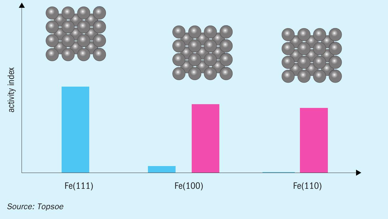
Achieving high catalyst activity requires not only the right amount and distribution of the promotors on the iron surface, but also the presence of a significant number of the highly active Fe(111) sites. The open iron surfaces of these sites make it easier for the gas reactants to access the catalyst surface, which in turn means they exhibit a much higher ammonia synthesis activity than the Fe(100) and Fe(110) sites, which feature a more closed iron structure.
Magnetite in itself does not have any preference for any of these sites, so it is merely something that can be controlled and optimised by selecting the right conditions during manufacture of the catalyst.
Some of this can be compensated for by the appropriate use of the most suitable promoters, but it can still never reach the full activity level of the Fe(111) sites, as illustrated in Fig. 1
The importance of promotor distribution
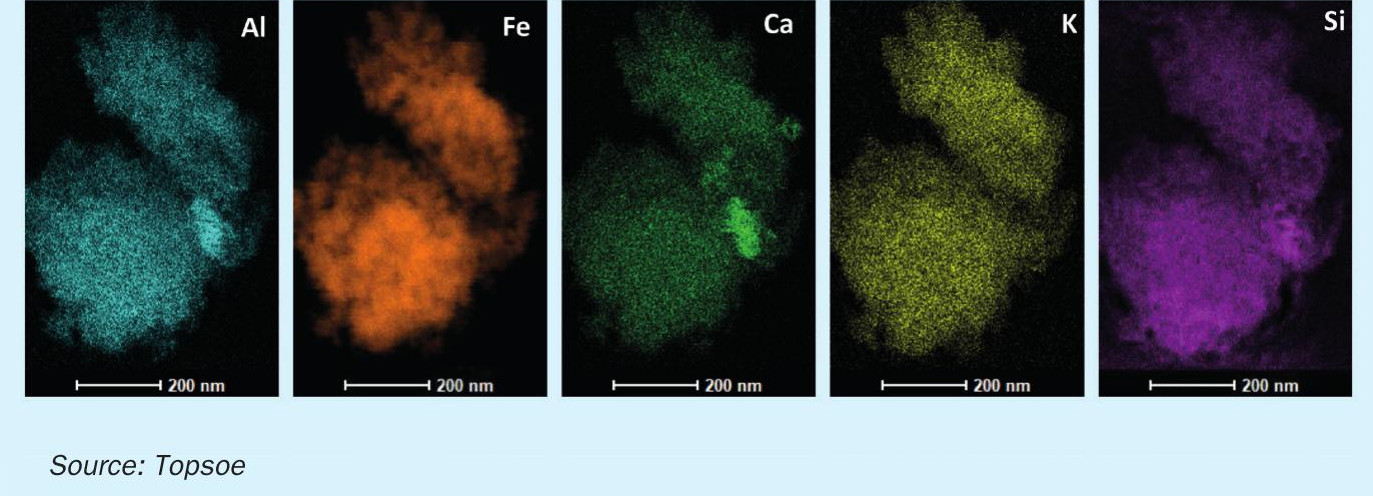
The use of structural promoters (such as Al, Ca, Si and Mg) significantly reduces the sintering of the active iron sites during the operation, and this in turn results in a very high catalyst stability and stable production rates of the industrial unit.
However, in order to achieve the best possible promotion effects, the individual promoters must be distributed very consistently throughout the iron surface. On magnetite, this is made possible by using the right specialist techniques while the catalyst is being fabricated. The even distribution of the different promoters is shown in Fig. 2.
Broadhurst et al.1 describe the promoter distribution on wüstite catalyst and conclude that it is very difficult to get an even promoter distribution on wüstite-based catalysts, and that this will lead to increased deactivation rates.
In order to investigate this further, the Topsoe research and development department carried out a number of ageing experiments on magnetite and wüstite-based catalysts.
The resulting effect on the deactivation rates is illustrated in Fig. 3, where ageing of the magnetite and wüstite-based catalysts has been carried out at 500°C and with a gas composition reflecting normal industrial conditions with a hydrogen/nitrogen ratio of 3. The experiments ran at a pressure of 20 Mpa.
The accelerated ageing shows that the magnetite-based material loses only 10% of activity during the test, whereas the wüstite based material loses substantially more at 30% of its SOR activity.
Stability of pre-reduced ammonia synthesis catalyst
A loading of ammonia synthesis catalyst will normally consist of a pre-reduced layer for the first bed and oxidic catalyst for the lower beds. The oxidic catalyst in the lower beds will then have to be reduced in situ over a number of days, in conjunction with the start-up.
There are plants where pre-reduced catalyst is installed in all the catalyst beds in order to save start-up time and to reduce the amount of ammonia-containing water generated during the catalyst reduction. A plant can normally save two to three days of catalyst reduction time and thereby gain a significant amount of extra ammonia product during this period.
Manufacture of the pre-reduced catalyst is done in a separate step after the oxidic catalyst has been produced. Most catalysts are pre-reduced at the same facility as the oxidic catalyst, but in some cases it is carried out by third parties.
It is critical that this reduction step is completed in a way that ensures maximum activity is achieved because this is where the crucial pore structure of the catalyst is created. This means that heating rates and water content must be carefully controlled and monitored during the pre-reduction process.
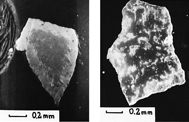
Raiser and Baranski2 carried out a detailed investigation of this, and Fig. 4 shows pictures of the influence on the water content during reduction. When the reaction is fast, the reduction occurs in a narrow zone that moves progressively from the outer surface to the unreacted dense centre (left). When the reaction is inhibited, perhaps due to the presence of high concentrations of water, there is an uneven profile of reduction degrees throughout the iron particles (right).
After full reduction has been achieved, a separate passivation step needs to be completed. Without the right passivation, the handling and loading of the catalyst will be at risk because the catalyst may begin to heat up when it comes into contact with air.
Such heating up can result in significant delays of the loading activity and will also, in most cases, require that the reactor is blanketed by nitrogen. The result will most assuredly be a catalyst activity that is lower than expected, so this catalyst should be discarded if possible.
From research investigations to practical experience
So how does magnetite perform in practice in real world industrial units?
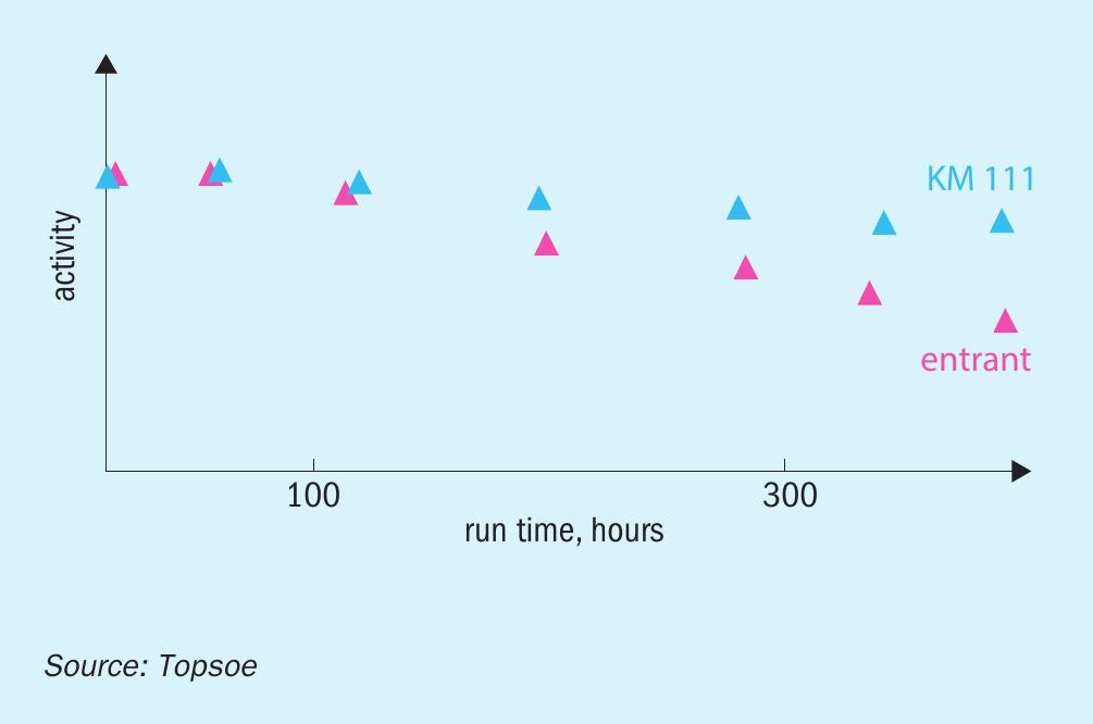
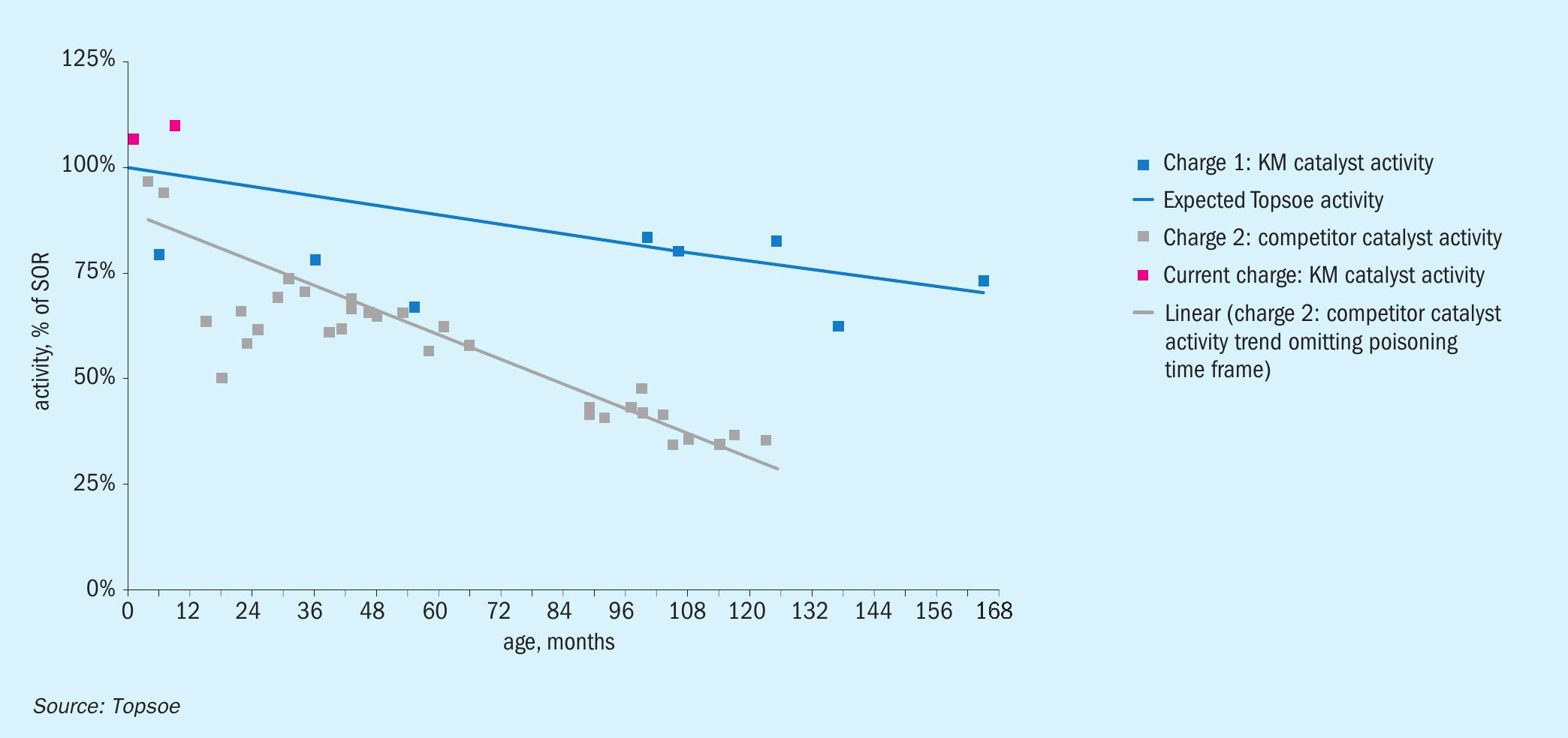
After more than 13 years of operation with the Topsoe KM magnetite-type catalyst, a plant located in North America switched over to a wüstite-based catalyst (Fig. 5). This catalyst showed much faster deactivation than had been encountered with the previous KM charge, and after ten years of operation the plant decided to replace it and to return to using the KM magnetite-based catalyst. The first 12 months of operation confirmed the very high activity level of the new Topsoe catalyst.
Industrial feedback and years of research by Topsoe into the magnetite phases and appropriate promoters resulted in the launch of the KM 111 and the pre-reduced KMR 111 catalysts in 2014.
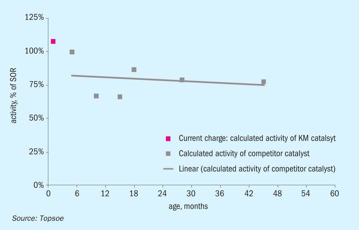
Since their introduction, these ammonia synthesis catalysts have been installed in more than 70 ammonia plants worldwide. This currently represents 25% of all plants for which Topsoe has provided catalyst solutions for ammonia synthesis. A recent example of a KM 111 installation is in a US ammonia plant, where it replaced a wüstite catalyst (Fig. 6). The three-bed reactor installed in this plant uses a pre-reduced catalyst in the first bed and KM 111 as the catalyst in in the second and third beds.
The wüstite-based catalyst was replaced four years after installation due to mechanical issues in the ammonia converter. The plant decided to install magnetite-based KM 111 on account of its lower deactivation and higher activity properties.
Conclusion
Selecting the right type of ammonia synthesis catalyst can have a big impact on plant economics. Magnetite-based catalysts have been considered the ideal choice for use in ammonia synthesis converters for well over a century. With the recent developments within iron surface sites and promoter compositions, they continue to be selected throughout the industry due to their positive impact on plant reliability and plant economics.
References