Nitrogen+Syngas 380 Nov-Dec 2022

30 November 2022
An experience of secondary reformer refractory casting
AMMONIA PLANT EQUIPMENT
An experience of secondary reformer refractory casting
Refractories are heat resistant materials used in high temperature processes to protect industrial equipment such as utility boilers, heaters, and ammonia primary and secondary reformers against heat and chemical attack. In this article Hasan Akbari of Kermanshah petrochemical Industrial company (KPIC) reports on experiences of different stages of refractory casting in the secondary reformer of an ammonia plant, located in Kermanshah province of Iran (KPIC – Phase II). The pouring operation was carried out in three stages and each section was cast nonstop for a period of three days in total.
The secondary reformer is an integral part of the synthesis gas generation in a conventional ammonia plant. The three main processes taking place in the secondary reformer are: mixing of air and process gas, combustion of hydrocarbons, and methane conversion by steam methane reforming over the catalyst bed.
The role of the secondary reformer reactor is to produce and adjust the amount of hydrogen and nitrogen gases. The process gas leaves the primary reformer through the transfer line and enters the secondary reformer at the top through the combustion chamber, where it is mixed with process air. The processes taking place in the combustion chamber liberate heat which raises the temperature of the product gases from the primary reformer. The partially oxidised gas passes through the catalyst zone to produce the hydrogen. Combustion of the process gas with air produces a gas temperature of 1,100-1,200°C in the upper section of the secondary reformer. Because the reforming reaction of methane absorbs heat, the temperature decreases as it passes through the catalyst and finally the reformer gases leave the secondary reformer through the outlet nozzle at the bottom of the reactor. Fig. 1 shows a schematic view of a secondary reformer1 . The inside of the secondary reformer is lined with insulating refractory to optimise energy use. The insulating refractory reduces the rate of heat flow through the walls of the furnace, keeping the temperature of the outer side of the shell below 110°C. Use of high purity, low silica alumina bubble castable has been accepted as insulation for hot pressured hydrogen lines. The shell must also be water jacketed to prevent failure due to overheating2 .

Refractory material
Refractories are inorganic, non-metallic, porous and heterogeneous materials composed of thermally stable mineral aggregates, a binder phase and additives. The principal raw materials used in the production of refractories are: oxides of silicon, aluminium, magnesium, calcium and zirconium and some non-oxide refractories like carbides, nitrides, borides, silicates and graphite.
Environment, temperature, and the materials in contact with the refractory are some of the operating factors that determine the composition of refractory materials. Important properties of refractories are: chemical composition, bulk density, cold crushing strength (CCS), permanent liner change (PLC), abrasion resistant and grain size. Refractories can be classified on the basis of chemical composition and the methods of manufacture or physical form.
Classification of refractory based on chemical compositions
Acid refractories
Acid refractories are those which are attacked by alkalis (basic slags). These are used in areas where slag and the environment are acidic. Examples of acid refractories are silica (SiO2 ) and zirconia (ZrO2 ).

Neutral refractories
Neutral refractories are chemically stable to both acids and bases and are used in areas where slag and the environoment are either acidic or basic. Common examples of these materials are: carbon graphite, chromates (Cr2 O3 ), and alumina.
Basic refractories
Basic refractories are those which are attacked by acid slags but stable to alkaline slags, dusts and fumes at elevated temperatures. Since these do not react with alkaline slags, these refractories are of considerable importance for furnace linings where the environment is alkaline, for example non-ferrous metallurgical operations. The most important basic raw materials are magnesia (MgO), dolomite (CaO*MgO) and chromite.
Chemical characteristics of the furnace process usually determine the type of refractory required. Theoretically, acid refractories should not be used in contact with basic slags, gases and fumes, whereas basic refractories can be best used in an alkaline environment. Actually, for various reasons, these rules are often violated.
Classification based on physical form
Refractories are classified according to their physical form; these are the shaped and unshaped refractories. The former is commonly known as refractory bricks and the latter as “monolithic” refractories. Shaped refractories are those which have fixed shape when delivered to the user. Unshaped refractories are without definite form and are only given shape upon application. These are categorised as plastic refractories, ramming mixes, castable, gunning mixes, fettling mixes and mortars3 .

Secondary reformer and its refractory at KPIC
The secondary reformer at KPIC is a vertical vessel with an external jacket and with a maximum working pressure of 41.6 bars. The operating temperature of the reactor is different in different section and varies between 1,277°C and 650°C from top to bottom section. The reactor height is 19,351 mm and the maximum and minimum diameter of vessel varies from 3,780 to 1,120 mm. The design thickness of the internal refractory is between 275 mm and 400 mm and the required weight of refractory was estimated to be 125 t. The reactor has an internal dome brick that supports the weight of the internal catalyst.
The type of refractory used in the secondary reformer was high alumina castable (shell area) and brick (dome brick area) with a blended mixture of tabular alumina and low iron calcium aluminate binder. The physical properties of the refractory are shown in Tables 1 and 2.
Properties of refractories
The most important properties of refractories to be checked according to the datasheet were chemical composition, bulk density, cold crushing strength, and permanent liner change. Preparation, drying and firing of test specimens were performed according to API 936.
- Cold crushing strength is the maximum applied load per unit area that the refractory material will withstand. The test was carried out in accordance with ASTM C133.
- Density is calculated at room temperature by dividing refractory weight by refractory volume in unit kilograms per cubic meter.
- Permanent liner change is the expansion or contraction that remains in a shaped refractory product that is heated to a specific temperature for a specified time and then cooled to ambient temperature. The test was carried out in accordance with ASTM C1134.
Material qualification
Before packaging the refractory material at the manufacturer site, all of the abovementioned necessary tests were performed. Other tests such as abrasion loss, workability index according to the data sheet were not applicable. An inspector directed sampling, preparation and witnessed the testing. The number and size of specimens for the required tests is shown in Table 3.
Specimens were dried and fired according to the following procedure:
- Oven dry: hold for 12 hours minimum at 104°C to 110°C in a dryer.
- Oven fire: heat at 170°C/h maximum to 815°C, hold for five hours at 815°C and then cool at 280°C/h maximum to ambient.


After checking the experimental results with the product datasheet, the raw refractory material was accepted.
Vessel preparation for refractory casting
All activities before casting of refractory that involved checking of anchor bolts, internal forms, cardboard installation and surface cleaning were carried out as detailed below.
Anchor bolt check
The refractory lining is fixed by anchors with cellulose acetate caps. The purpose of these anchors is to strengthen the refractory. All of the anchors were installed at the shop of the manufacturer and were visually checked again at site. The material of construction of the anchors was SS330 and was approved by PMI test. A hammer test had also been used to test the mechanical strength of the welding. All anchors were checked by the vessel fabricator to ensure that the anchor pattern was followed, the anchor welds were sound and none of the anchors were bent out of position. The anchor caps were installed at the site and checked visually (Fig. 2).
Formwork assembly
Prior to assembling metal formworks, cardboard had been wrapped around some internal surfaces such as nozzles and the dome skirt. The next step was to assemble the formworks in the reactor. The formwork installation proceeded from bottom section to top section, step by step. The connection between the separate parts of the formworks was bolted construction with mineral oil coated on the outside surface of the forms to facilitate their removal from the shaped refractory surfaces. The metal forms were stiffened by jigs in the middle section at different heights to prevent deformation and movement due to the vibration and pressure of the refractory material being cast. Pouring holes were installed peripherally to execute refractory casting by a flexible hose. The pouring holes were installed so that the maximum drop in pouring does not exceeds 3 m. From these openings, the thickness of the lining is measured and then, the arrangement of the metal forms was approved. The forms in the top section were installed after casting the bottom and middle sections of vessel (Fig. 3).
Requirements for casting of refractory
Before installation, it was very important to plan the execution of work. First, it was necessary to make sure that all materials and equipment were available. According to refractory manufacturer advice, the ambient temperature and the temperature of the surface onto which the refractory is installed, should be between 16°C and 25°C. Since the refractory was poured during winter, in the cold weather season, it was necessary to heat the water artificially until the operation was complete. It was also very important to use only potable water, containing no salts or foreign substances so, Chemical analysis according to recommended procedures was therefore carried out to check the suitability of the water quality. Checking the manpower and necessary equipment and tools was another step towards issuance of the permit. Required tools and equipment for installation included a crane, diesel generator, horizontal mixers, vibrator, thermometer, heater, and flexible hose in sufficient numbers.
Mock-up test
A mock-up sample was prepared before casting into the vessel to simulate the most difficult pieces of the installation work, including mixing, handling and associated quality control requirement.
The refractory thickness, anchors, anchor pattern and the vibration method were in accordance with the actual installation job. Refractory cast in the mock-up piece cured at least 24 hours prior to stripping the forms. Visual inspection of the refractory showed an acceptable surface with minor cavities and some minor cracks that were less than 0.5 mm wide. The mock-up test highlighted some effective parameters which helped to improve the quality of work. Mixing time, mixing temperature, water temperature and vibration method were four important parameters that received a lot of attention during the main work (Fig. 4).
The sample was also broken and inspected visually at its cross section before carrying out all of the necessary tests according to Table 3 and checking with the datasheet that the results were acceptable.
Mixing Procedure
Prior to installation, some bags of castable refractory were inspected for any signs of hydration. Castable refractory was mixed with a ratio of 7.5-10% by weight of water using a paddle horizontal type mixer before charging into the hopper (Fig. 5).
Optimum water percentage was an important parameter to ensure adequate strength and to avoid cracking during the dry out procedure. The mixture and water temperature were checked by a laser thermometer. The acceptable range for both water and casting mixture was 16-37°C and was maintained by adding hot or cold water. According to mixing instructions, the raw refractory was mixed in the dry state and then sufficient water was added gradually. Mixing continued for two to three minutes after completion of refractory and water addition. The refractory was poured within 20 minutes from the time of preparation and mixing to avoid the material from losing its workability and ease of flow (Fig. 6).
a)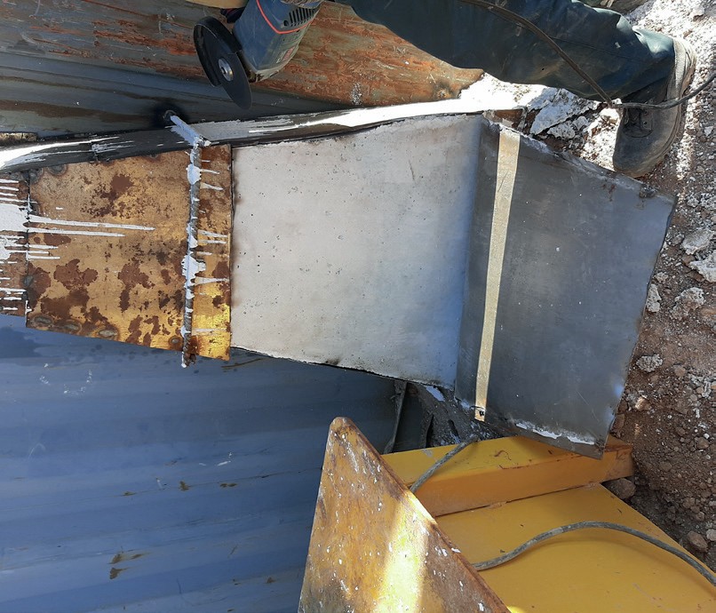
b)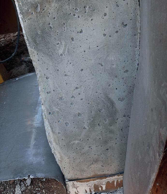
a)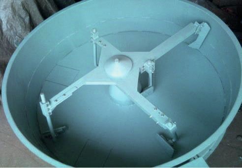
b)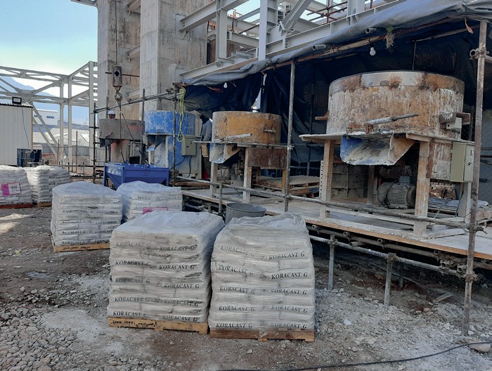
Before casting, the “ball in hand” Test according to ASTM C860 was used to determine the correct consistency5 . Sufficient water should be added to allow the castable to hold together in a ball when “bounced” in the palm of the hand. If too dry, the ball will break up into a crumbly mass; if too wet, it will slump through the fingers. This “bouncing” in the hand should impart a slight glistening to the surface of the ball of concrete but there should be no appreciable transfer of water and cement to the palm (Fig. 7).
Pouring procedure
The casting was executed in three stages, bottom, middle and top section. The refractory mass of the sections was 16, 80 and 14 t respectively. Important equipment and accessories for casting of the refractory were: two cranes, four mixers, internal scaffolding, flexible hose and chute, hopper, internal light, load speaker interphone and a water drum. The layout of the equipment for refractory casting is shown in Fig. 8.
a)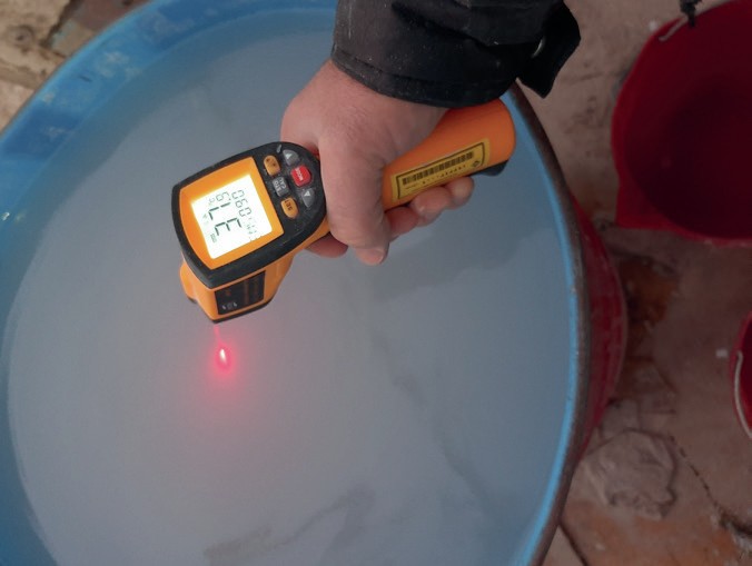
b)
The different stages of pouring are described below.
A hopper was installed on top of the manhole flange of the reactor and flexible hose and a chute were set in the opening of the bottom section forms to initiate casting.
Castable refractory was transferred to the top of the vessel by crane and drained into the hopper and then through the flexible house and chute into the opening of the forms. During casting and before the refractory reached the bottom of the window (opening) being used, the lower window was closed and the next higher level window was used.
After pouring a batch of refractory, the worker responsible for vibration began vibration internally and externally for 30 to 40 seconds to consolidate the material being cast and to eliminate air bubbles. Close attention is required during vibration to prevent segregation of refractory material and the formation of air bubbles. It is important that the internal vibrator is not removed too quickly which can leave voids in the lining.
By raising the level of casting refractory in the forms, the flexible hose had to be cut according to the height of the pouring holes height to ease setting the chute into the pouring window (Fig. 9).
During the casting two production refractory samples prepared by standard dimensions were tested, e.g., for density, PLC and CCS (Fig. 10). The results of the tests are shown in Table 4.
Curing of Refractory
After pouring the refractory and for bond formation in the new monolithic installed refractory, the curing process was carried out for a minimum of 24 hours at 10°C to 32°C according to manufacturer’s recommendations and before stripping the forms. The curing temperature of the vessel was maintained by an electrical heater.


a)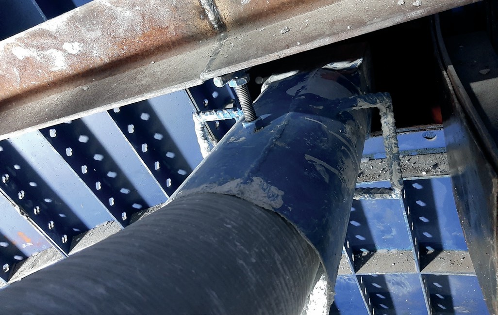
b)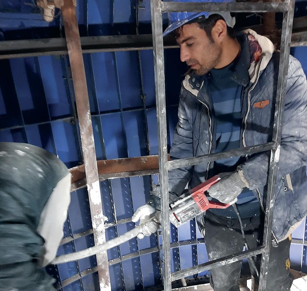
Removing the forms
After casting and curing the refractory, all forms were removed and the entire internal surface was checked visually. Observations showed some distributed cavities with a maximum depth of 3 mm and also some cracks that were less than 0.2 mm wide. In some locations such as the form’s window and seams between separate parts of the metal forms there were projections of refractory that were removed by grinding to a smooth surface.

Dome brick installation
Before dryout, internal dome brick was installed consisting of 12 layers (A,B,C,D,E,F,G,H,I,L,M,N). The skew section of the dome consists of three layers (A,B,C) (168 bricks) and the rest of the bricks were laid on the dished section of the dome (259 bricks). Bricks were laid carefully in each layer and cardboard of the same thickness as the mortar thickness was put into the joint spaces of the bricks to check the adjustment of every layer. After assurance of the correct position of the bricks, they pieces of cardboard were removed one by one and replaced with mortar. After placing the three layers of bricks in the metal support (A, B, C), wooden beams and probes and polystyrene forms were set in the bottom section of the reactor. Initially, 22 wooden probes and 9 wooden beams were installed in the bottom section and fixed to each other with nails, plywood sections were then laid on the probes and beams and finally polystyrene forms were placed on the plywood in the correct positions. Installation of the remaining layers (D,E,F…N) commenced after setting the polyester forms and wooden structures After installation of the last brick (M), wooden beams and probes and polystyrene forms were carefully disassembled and removed via the bottom manholes (Fig. 11).

a)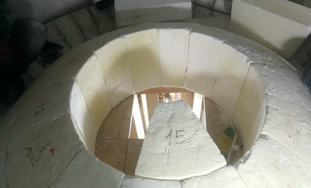
b)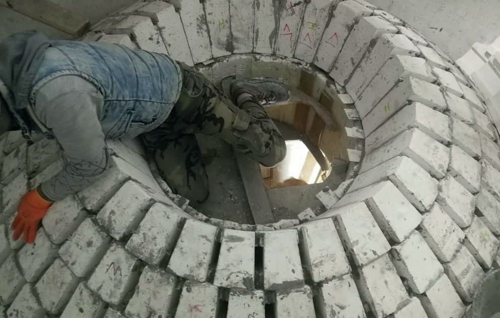
c)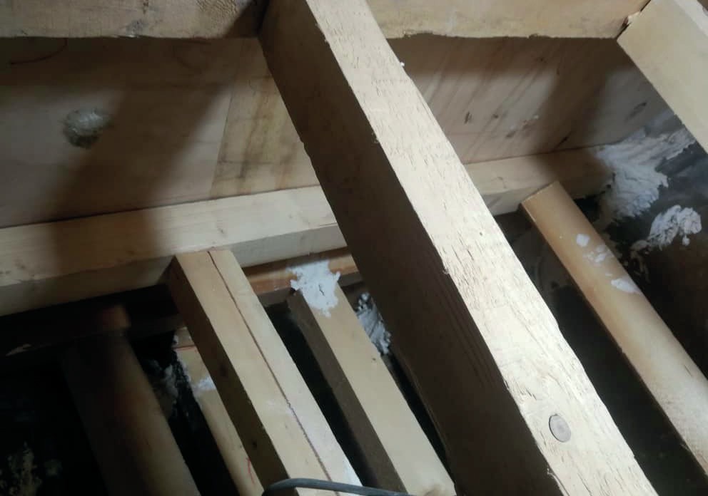
d)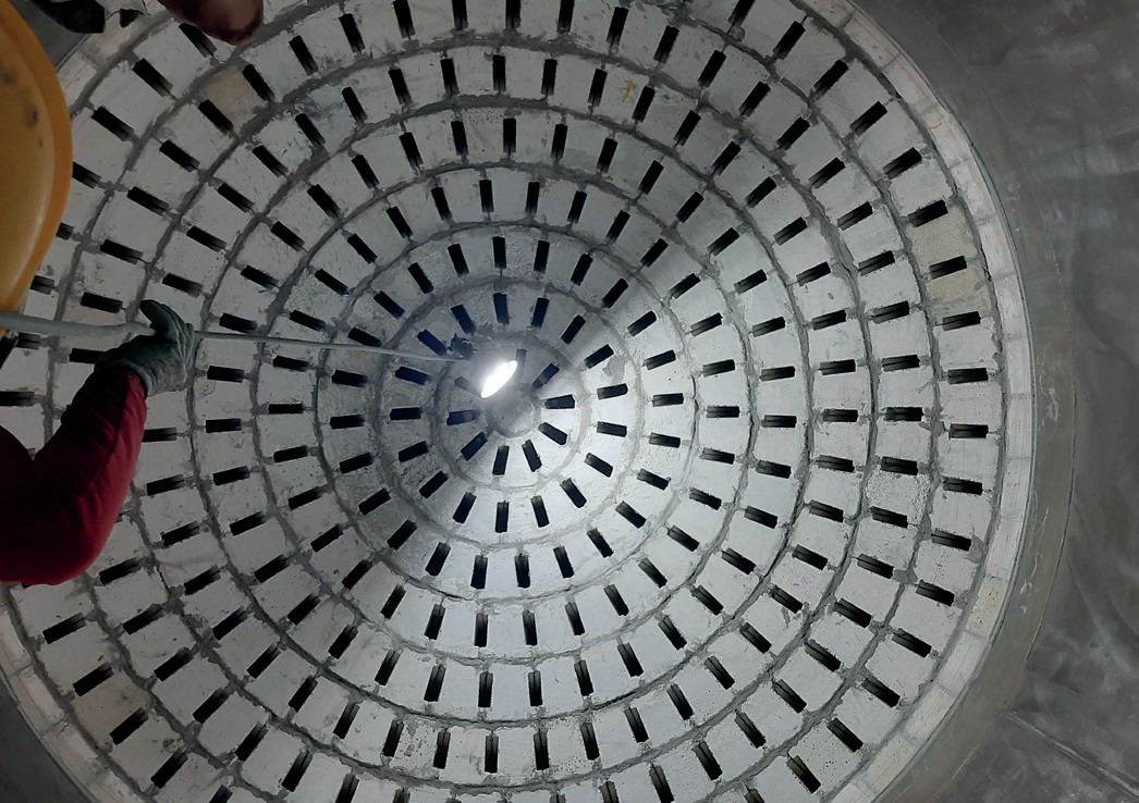
Dryout
The combined efforts of refractory manufacturer, installer and dryout contractor will result in optimal refractory performance. The dryout process is necessary to reduce the quantity of water in the concrete that may cause undesired reaction like “alkaline hydrolysis”. This operation is carried out at the end of the refractory installation and after the curing. Dryout of refractory linings is carried out by applying heat under controlled conditions using high velocity burners. The products of combustion are exhausted through a suitable opening located at the unit outlet.
Thermocouples and burner
Before dryout was started, sufficient temperature measuring devices were installed on the refractory surface using a high temperature resistant glue to monitor the temperature throughout the area to be dried. Accurate drying control requires the correct location of thermocouple probes and efficient heating apparatus. Nine thermocouples probes (type k) were placed 12 mm away from the lining surface.
Direct flame impingement on the refractory surfaces was not allowed so the burner was installed via the bottom manhole to avoid damage caused by overheating the refractory, dome brick and other components. The volume of air passing through the lined equipment was checked that it was sufficient to avoid saturation before it reached the outlet. According to the refractory manufacturer recommendations, the minimum blower capacity should be 60 m3 per hour for each square metre of burner and burners should have a capacity of at least 50% excess air at the maximum intended firing rate6 . The burner fuel was LNG, which was supplied by a special truck to a LNG storage tank that had all of the required safety devices and had been certified by a valid institute (Figs 12).

Dryout sequence
The procedure for heating and cooling the refractory was carried out according to the following steps:
- Ignite the air heater burner at minimum load and adjust to obtain an initial heat up rate of 27°C/h (for about 5 hours) up to 120°C maximum.
- Hold the temperature of 120°C for 12 hours minimum.

- Increase the temperature at 27°C/h up to 315°C.
- Increase the temperature at 17°C/h up from 315°C to 400°C.
- Hold this temperature for 12 hours minimum.
- Increase the temperature at 40°C/h up to 565°C.
- Hold this temperature for 12 hours minimum.
- Cool down the equipment gradually (about 55°C/h) to ambient temperature.
Before start of operation, the position of all internal thermocouples and their distance from the refractory surface was checked. The sensed temperature of every nine thermocouples was plotted by a calibrated recorder in a single graph. The temperatures could also be seen digitally on the recorder (Fig. 13).
According to thermal calculations from the refractory designer, the maximum temperature of external surface of reactor should not exceed 113°C. The maximum temperature of the external water jacket that was monitored by thermometer reached 111°C at the bottom section where the inside burner has been installed and on other sections its maximum value was 75°C, therefore there were no hot spots on the external surface of the vessel during the dry out process.
Inspection after dryout
All of the refractory surface was inspected visually after dryout. According to procedures, cracks wider than 2 mm were considered defect and needed to be repaired. A hammer test with a ball-point machinist hammer also took place when the refractory material has taken its final set. When defective areas were encountered (voids or dry-filled spaces), a dull sound would be heard. Voids or hollow sounding areas larger than 150 x 150mm and any soft or “dry fill” areas that reduced the effective lining thickness by more than 25% of the original thickness or more than 13 mm were considered defect and required repair. The maximum width of cracks after dryout were less than 2 mm. The maximum depth of cracks was also checked with a wire of 0.6 mm that was less than 5% of total thickness of refractory. The hammer test also did not show any defects on the refractory surface (Fig. 14).


Visual inspection of the refractory after dryout revealed that there was a thin layer of soot (carbon layer) in the top section of the vessel (the surfaces after dome brick) but there was no soot on the dome brick or the region under the dome brick. Checks by process and inspections teams concluded it was due to incomplete combustion from the burner during dryout. According to API 571 only sulphur is harmful for refractory, so the inspection team did not believe the carbon would influence the refractory surface. In the opinion of process team and because of the operation conditions of the reactor temperature >1,000°C and pressure >40 bars), this layer will be burned and vanish in the commissioning step. In addition, the internal surface of the refractory was cleaned of remaining soot as much as possible.
After ending the dryout process, the graph of all the thermocouples was checked and compared with the accepted procedure. Because the position of thermocouples 1, 2 and 3 were near the burner flame, the maximum temperature of 800°C had been reached. However the criteria for temperature was based on thermocouples 4, 5, 6, 7, 8 and 9 which had been positioned on top of dome brick and had minor differences with each other during the heating process.
Conclusion
The secondary reformer has an important role in the ammonia production. The function of the refractory lining in the reactor is to reduce the rate of heat flow through the walls of reactor. The assemby and adjustment of internal forms, mixing of material with water, pouring the refractory, curing and dryout of the refractory, dome brick installation and performing the required tests during this process are effective parameters to achieve a good quality of installed refractory. Refractory insulation at KPIC was performed in three steps. Lasting three days in total. Dryout was performed using an LNG burner according to an accepted graph. Inspection of the internal surface of the refractory showed that cracks after dryout were in the allowable range and acceptable.
Acknowledgment
The author appreciates Mr F. Khosravi and Mr F. Siahkamari for their support and thanks the IREFCO company (Ms. Fereshteh Moradi) and Tabesh company (Mr.Rezaei and Mararanjani) for their contributions supplying the raw material and during installation stages. Special thanks also to Mr S.Ghiasi and Mr M. Safaie, without their help it would have been very difficult to carry out this project.
References