

Sulphur 404 Jan-Feb 2023

31 January 2023
CO2 recovery options in sulphur plants
ENVIRONMENTAL PROTECTION
CO2 recovery options in sulphur plants
CO2 emission abatement strategies have become increasingly important as the world strives to combat global climate change. Mahin Rameshni and Stephen Santo of Rameshni & Associates Technology & Engineering (RATE USA) discuss carbon capture options available for sulphur recovery units.
The global concentration of CO2 in the atmosphere is increasing rapidly. CO2 emissions have an impact on global climate change. Power generation from fossil fuel-fired power plants (e.g. coal and natural gas) is the single largest source of CO2 emissions. However, fossil fuel-fired power plants play a vital role in meeting energy demands. For instance, coal-fired power plants can be operated flexibly to meet varying demand. With growing concerns over the increasing atmospheric concentration of anthropogenic greenhouse gases, effective CO2 emission abatement strategies such as carbon capture and storage (CCS) are required to combat this trend.
CCS is a process consisting of the separation of CO2 from industrial and energy-related sources, transport to a storage location and long-term isolation from the atmosphere. The three basic stages of CCS can be summarised as:
- separation of CO2;
- transportation;
- storage.
There are three major approaches for CCS:
- post-combustion capture;
- pre-combustion capture;
- oxyfuel process.
Post-combustion capture offers some advantages as existing combustion technologies can still be used without the need for radical changes to them. This makes post-combustion capture easier to implement as a retrofit option compared to the two other approaches. For this reason, post-combustion capture is most likely to be the first technology that will be deployed.
A number of separation technologies can be employed for both pre- and post-combustion capture. These include:
- adsorption;
- physical absorption;
- chemical absorption
- cryogenic separation;
- membranes;
- RATE technology CO2 liquefaction.
Several advanced and improved configurations are available for amine-type designs and will be discussed in this article.
RATE recently filed a patent application that covers the combination of CO2 recovery and hydrogen generation in SRUs but it has not yet been published by the US Patent office.
Pre- and post-combustion capture
RATE offers several options for pre-combustion and post-combustion CO2 removal.
Amine-type CO2 removal has been used widely in pre-combustion and post-combustion units. In post-combustion capture, due to the presence of oxygen, the type of solvent selected should tolerate oxygen, like MEA, and a thermal reclaiming system is required to remove degraded components. Post-combustion capture and storage (PCCS) units comprise CO2 absorption by 30 wt-% monoethanolamine (MEA) solution and CO2 compression at 150 bar for permanent storage or enhanced oil recovery.
However, PCCS amine type technology needs substantial amounts of thermal energy for absorbent regeneration and electricity for carbon capture, CO2 compression as well as for the operation of other parasitic electricity consumers. The PCCS energy requirements vastly affect the overall plant performance. It produces more CO2 by supplying thermal energy for CO2 removal, resulting in insignificant net CO2 removal.
One option to optimise the amine configuration to reduce the thermal energy consumption is to have multiple stages of the flash drum to remove the CO2 before the regeneration system (see Fig. 1).
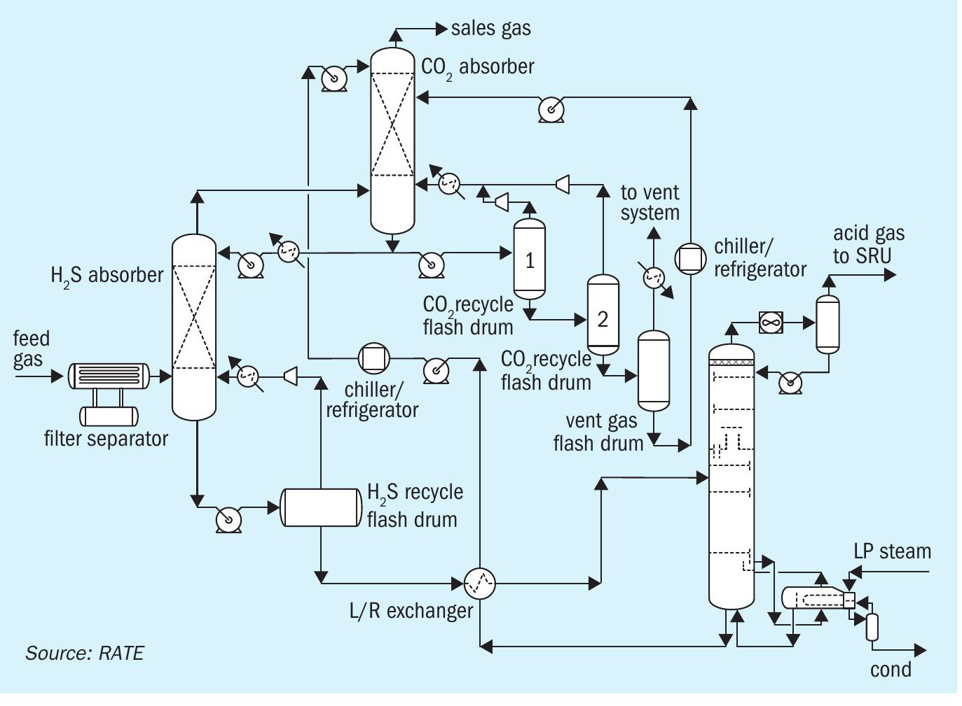
This configuration uses a physical solvent and works best when both the acid gas concentration and the operating pressure is high. It is a non-reactive process with no degradation product and no reclaiming. It is a non-corrosive process using primarily carbon steel construction. The feed gas is contacted with the cool regenerated solvent, which removes CO2 and H2S from the gas phase and the absorbed gases are removed by thermal regeneration in a stripper.
A substantial amount of CO2 is removed in the multiple flash stages before entering the regeneration which significantly reduces the thermal energy required for regeneration.
In the pre-combustion process chemical solvents like MEA, MDEA based, aMDEA and physical solvents like Selexol, Rectisol or similar are commonly used.
Fig. 1 represents pre-combustion CO2 removal where the CO2 is removed before the acid gas enters the sulphur recovery unit (SRU). There are several advantages to this scheme. By removing the majority of the CO2 upstream of the SRU, the size of the sulphur plant is reduced significantly, resulting in lower capital and operating costs. Other advantages are that the CO2 is removed without increasing the thermal energy for the regeneration reboiler and by adding an extra absorber the CO2 is removed.
This configuration is evaluated based on the feed composition to the amine gas regeneration unit (AGRU) for the new facilities. The new sulphur recovery and tail gas unit will have less volumetric flow, the H2S concentration is richer and will achieve better operation while the CO2 has already been removed and the unit is designed based on new carbon capture. This scheme has been in operation in USA gas plants.
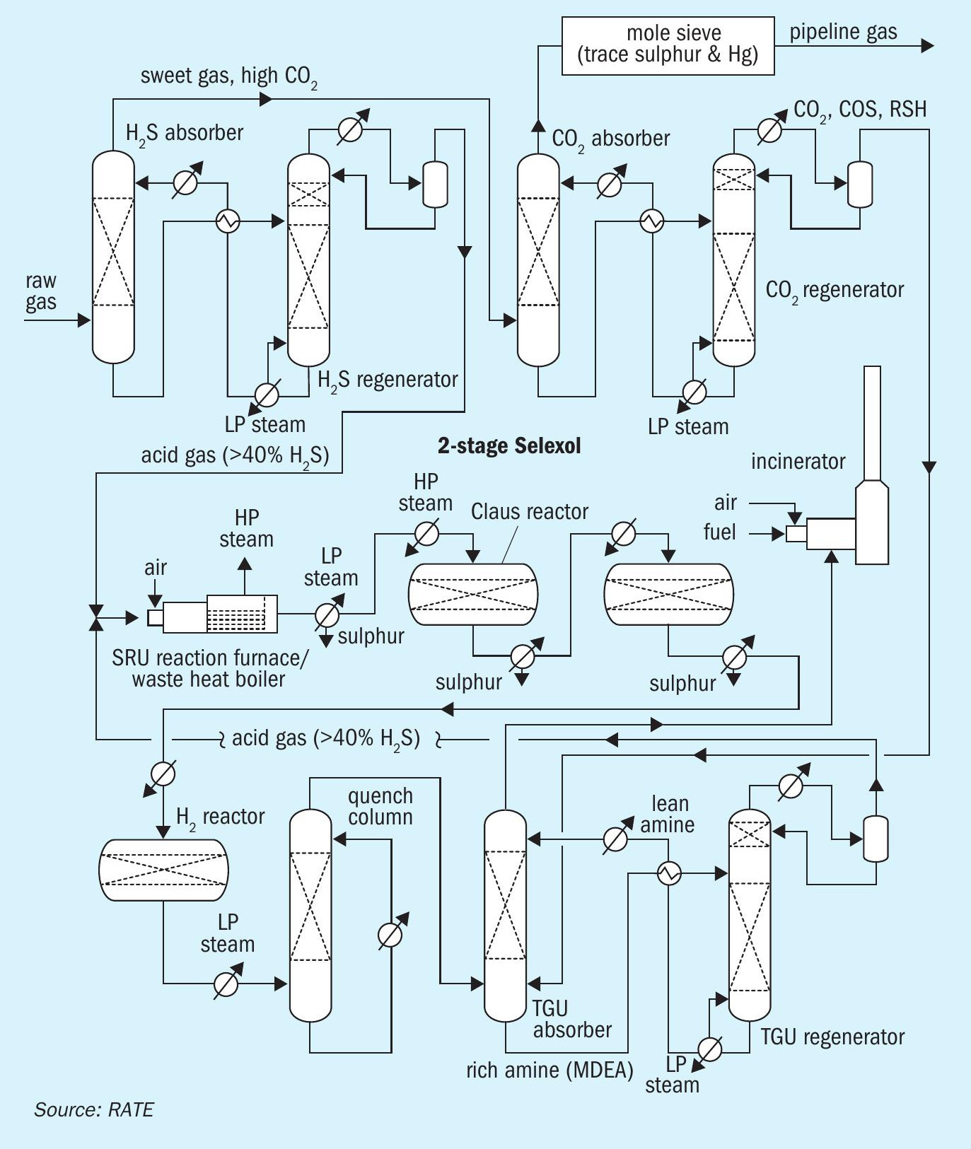
Another option, shown in Fig. 2, represents pre-combustion capture upstream of the sulphur recovery units, where H2S and CO2 are separated by using a physical solvent such as Selexol and a molecular sieve as summarised below:
- Stage 1: CO2 removal using a two-stage physical solvent
– H2S absorber – overhead contains sweet gas and high CO2 goes to stage 2
- H2S regenerator – overhead goes to SRU to process H2S to sulphur Stage 2: CO2 absorber and CO2 regeneration
– CO2 absorber – overhead goes for water dew point control, Hg removal by molecular sieve and then to pipeline
– CO2 regenerator – overhead goes to the TGTU absorber
- Conventional two-stage Claus unit and tail gas treating unit.
A third pre-combustion CO2 removal configuration is shown in Fig. 3 and described below.
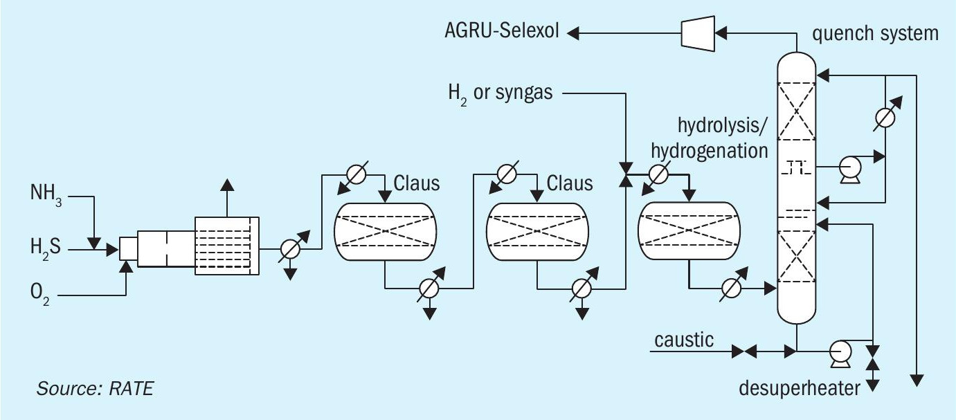
The acid gas removal scheme in this option is Selexol or Rectisol and the sulphur recovery is designed based on 100% oxygen enrichment. The tail gas treating unit contains an additional reactor for COS hydrolysis and to process the feed stream directly to maintain a high temperature in the SRU.
The tail gas unit is designed to recycle the quench overhead to the acid gas removal (Selexol, Rectisol) where the tail gas amine portion is eliminated and to achieve zero sulphur and CO2 emissions. The H2S and CO2 are sent to a unit using a physical solvent where CO2 is separated from H2S. The H2S is recycled to the SRU, and the CO2 is sent to another unit for compression.
CO2 removal from natural gas
RATE offers the combination of CO2 liquefaction with a two-stage membrane system for CO2 removal from natural gas as a pre-combustion configuration (see Fig. 4). If the H2S content is low, adsorbents are used upstream of the unit to remove the H2S, if the H2S content is high, the addition of a membrane is required to separate the H2S from the CO2. The recovered H2S is sent to the sulphur recovery unit.
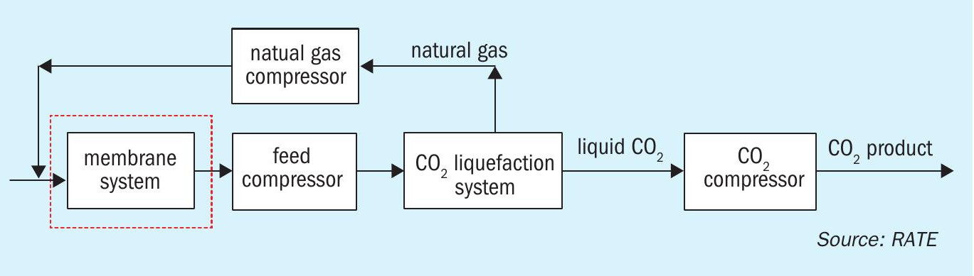
For a project with 950 million std ft3/d of the feed stream entering the membrane system, about 200 million std ft3/d of the gas was processed in the CO2 liquefaction. The capital cost saving from the combination of CO2 liquefaction and the two-stage membrane system versus CO2 removal using an amine solvent is about 40 to 45%.
Key advantages of CO2 liquefaction with a two-stage membrane system compared to conventional CO2 removal are:
- eliminates high amine circulation rate;
- significant reduction of consumption steam or fuel to provide heating media;
- reduces the number of items of equipment, especially large equipment;
- eliminates large absorber and regeneration columns;
- reduces plot space by providing a compact and modular unit;
- at least 40-45% saving in capital cost;
- reduces labour and time during construction.
A two-stage membrane process scheme is shown in Fig. 5.
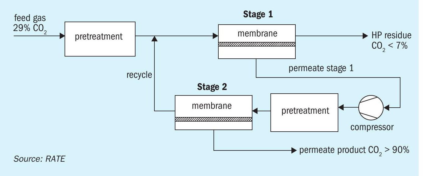
The feed gas is first passed through a pre-treatment section consisting of a filter coalescer, carbon bed, particulate filter, and heater. The heated gas is then routed to the first membrane stage, which separates the inlet gas into two streams:
- LP permeate stream: The membranes preferentially permeate CO2 and the resulting LP permeate stream, enriched in CO2, is compressed and sent to the second membrane stage for further CO2 recovery.
- HP residue stream, depleted in CO2 and more concentrated in the heavy hydrocarbons, is routed to the sales pipeline at high pressure.
For use in CO2 recovery processes, the design incorporates spiral-wound membrane modules. These modules consist of a densely packed sandwich of membrane envelopes and spacers in a spiral wound configuration around a central collection pipe (as shown in Fig. 6). 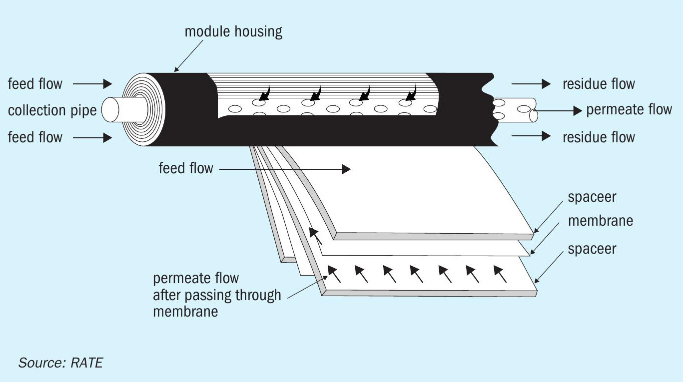
Mesh spacer materials create channels through which the feed gas and permeate vapours travel with minimum pressure drops. As a feed gas stream containing organic vapour passes across the membrane surface, CO2 passes preferentially through the membrane and enters the permeate channel. The permeate vapour spirals inward through the permeate channel to the central collection pipe.
To provide the driving force for permeation, a pressure difference is maintained across the membrane between the feed and the permeate stream. The pressure difference can be obtained by compressing the feed or by using a high-pressure feed stream and maintaining the permeate at a lower pressure by connecting it to a lower pressure point. This pressure difference directly affects the rate at which CO2 permeates the membrane. The larger the pressure difference, the greater the flux of CO2 through the membrane and reduction in the number of membrane modules needed to perform a desired separation.
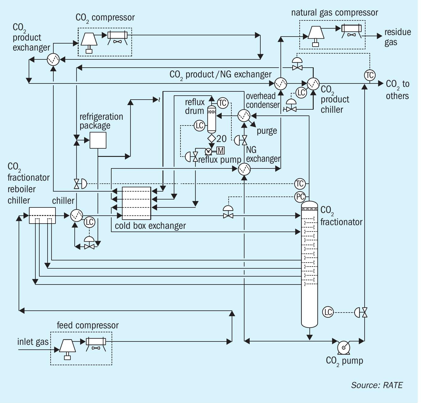
CO2 liquefaction is a process to separate CO2 from a mixture of hydrocarbons, mostly methane, to generate two streams, one is the CO2 and the other is the residue or natural gas. The residue is recycled back to the membrane system for further separation.
The dried gas enters the CO2 liquefaction unit where it is chilled by heat integration with the fractionation column (furnishing reboiler duty for the column). The gas is then further chilled and partially condensed in the refrigerant chillers using an external refrigerant. Next, the inlet stream is totally condensed and partially sub-cooled through further heat integration with streams leaving the cold section of the plant. Finally, it is flash expanded to the fractionation column at an optimum pressure designed for effective CO2 /methane separation while avoiding CO2 freezing issues.
Vapour leaving the column overhead is further chilled and partially condensed in the overhead condenser with CO2 refrigerant. The resultant CO2-rich liquid is pumped back to the fractionation column following further heat integration within the process.
The refrigerant for the overhead condenser is a portion of the CO2 product from the bottom of the fractionation column. This liquid CO2 is then flashed to a relative low pressure where it chills and partially condenses the overhead vapour stream. The volume fraction of CO2 in the gas leaving the reflux accumulator is approximately 21%. The CO2 used as refrigerant in the overhead condenser is then compressed, cooled, and returned back to the fractionation column where it is recovered in liquid form.
A distillation process for removing CO2 is designed with a feed gas stream under pressure that is cooled by heat exchange with other streams of the process and/or external sources of the refrigeration system. The gas is condensed as it is cooled, and the high-pressure liquid is expanded to an intermediate pressure, resulting in further cooling of the stream due to the vaporisation occurring during expansion of the liquids.
The expanded stream, comprising a mixture of liquid and vapour, is fractionated in a distillation column to separate residual methane, nitrogen, and other volatile gases as overhead vapour from the CO2 and the heavier hydrocarbon components as bottom liquid product. A portion of the liquid CO2 can be flash expanded to lower pressure and thereafter used to provide low level refrigeration to the process streams if desired.
Fig. 7 presents the process flow diagram for the CO2 liquefaction process developed by RATE. A portion of the produced CO2 is used as the chiller to eliminate an external chiller and save energy.
Post-combustion CO2 removal in SRUs
In a post-combustion amine unit, a suitable solvent can be used for CO2 removal, however, the main issue is the use of energy for the AGRU which can result in insignificant or uneconomical net CO2 capture.
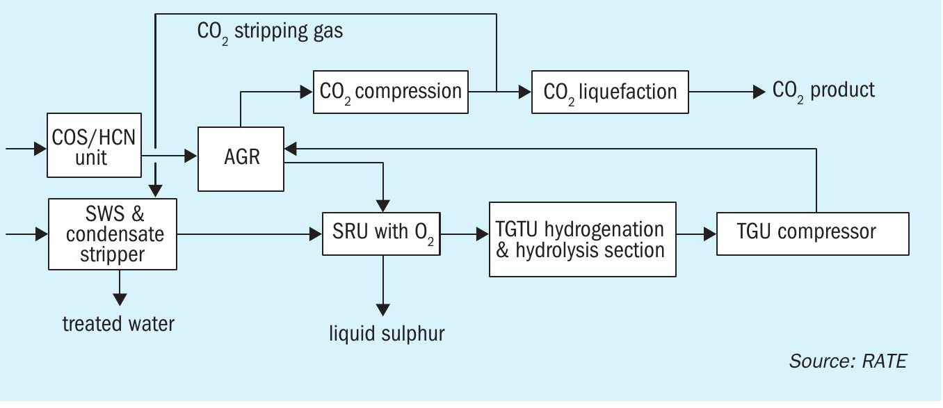
Recently, RATE has been working on a project for CO2 recovery and SO2 emission control in Europe. Fig. 8 shows the major units in the project.
Using CO2 liquefaction instead of an amine type unit is very economical and the required energy is significantly reduced.
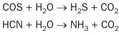
In the COS/HCN hydrolysis section, COS and HCN are catalytically converted into H2S, CO2 , NH3 and H2O which can be further removed from this plant. The conversion is described in the following hydrolysis reactions:
In the CO shift reactor, CO is converted to H2 according to the water gas reaction:
The gas stream from the hydrolysis section flows to the AGRU where a physical solvent, such as Selexol or similar, is used. In the AGRU, the treated gas containing high CO2 is sent to the RATE CO2 liquefaction unit for further purification.
The hydrolysis reactor after the hydrogenation reactor in the TGTU, so-called TG-MAX, is RATE’s patented technology (US 10,752,505 B2).
The purified CO2 can be reinjected or used in other applications such as a transport medium for solid waste conveying, a pressure medium for the lock hopper system, seal gas for feeding and withdrawing screw feeders or as a stripping gas. In this project, the CO2 is used as a stripping gas in a two-stage SWS design.
The H2S acid gas stream from the AGRU is converted to sulphur in the SRU using oxygen enrichment technology.
Fig. 9 shows the RATE CO2 liquefaction process for flue gas decarburisation, which is simpler than the pre-combustion CO2 liquefaction and membrane system.
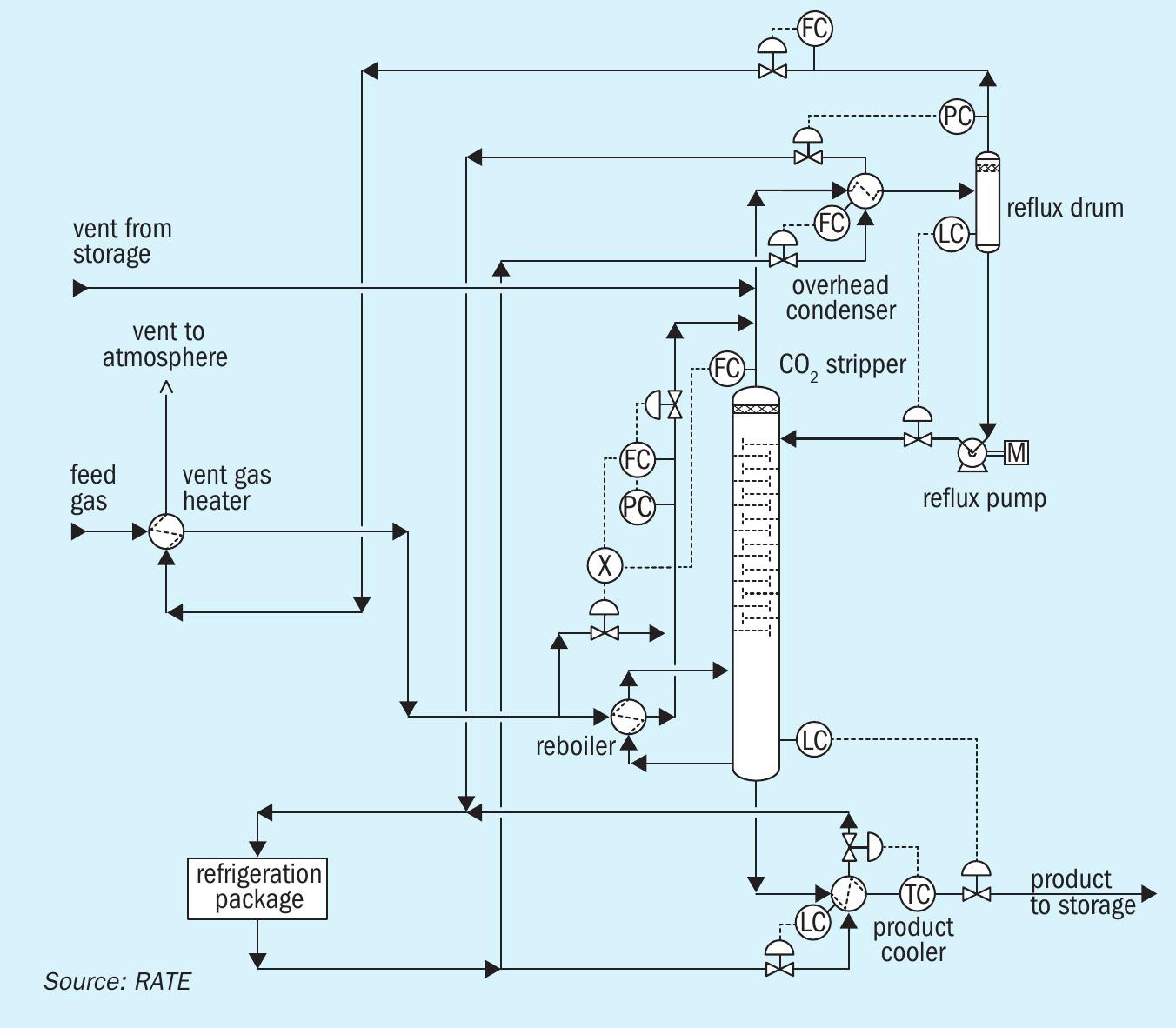
The proprietary RATE process condensate stripper uses CO2 as the stripping gas to strip H2S. This design is unique for this application.
The SWS and condensate stripper comprises two separate columns: the process condensate stripper and the NH3 stripper.
The first treatment step is the removal of sour gases and volatile components in the RATE process condensate stripper. The liquid phase of the process condensate flash drum is preheated and fed to the stripper column in between the upper and middle packing. the process condensate stripper column consists of two sections.
In the upper section, CO2 stripping gas is utilised to remove H2S and minimise stripping of NH3.
In the lower section, volatile components and CO2 are removed by means of uprising steam. Additionally, any dissolved carbonates are thermally decomposed. The stripped water is routed to the NH3 Stripper where NH3 is removed and mixed with H2S from another stripper and then routed to the sulphur recovery unit.
As already described, the design includes a COS/HCN hydrolysis unit, however, there is still some HCN and COS not fully hydrolysed which flows to the AGRU and eventually reaches the SRU. HCN can be washed as well as combusted in the reaction furnace and an additional feature has also been provided in the TGTU unit to hydrolyse all the remaining of COS.
In summary:
- The acid gas removal scheme uses Selexol physical solvent or similar.
- The SWS and condensate stripper is a unique design where CO2 was used as the stripping gas.
- The SRU is designed based on 100% oxygen enrichment single combustion.
- The tail gas treating unit (TGTU) contains an additional reactor for COS hydrolysis and to process one the feed stream directly to maintain a high temperature in the SRU.
- The TGTU is designed to recycle the quench overhead to the acid gas scrubber whereby the tail gas amine portion is eliminated and zero sulphur emissions are achieved.
CO2 removal in existing SRUs
Existing sulphur recovery and tail gas treating units are required to meet SO2 emission limits according to the local environmental regulations or world bank and various solutions are commercially available and have been used. In some places the stack is sulphur free, but CO2 is emitted. The easiest way to minimise the flue gas decarburisation is to add a unit to capture the CO2 before the stack.
One solution is to have an amine-type unit using a solvent that is suitable for the presence of oxygen, like MEA or similar. However, due to the significant energy required for the regeneration reboiler and electrical consumption resulting in additional CO2 being produced, the net decarburisation is not significant.
Adsorption is a physical process that involves the attachment of a gas or liquid to a solid surface. The adsorbent is regenerated by the application of heat (temperature swing adsorption, TSA) or the reduction of pressure (pressure swing adsorption, PSA). Adsorbents which could be applied for CO2 capture include activated carbon, alumina, metallic oxides and zeolites. Current adsorption systems may not be suitable for application in large-scale power plant flue gas treatment. At such scale, the low adsorption capacity of most available adsorbents may pose significant challenges. In addition, the flue gas streams to be treated must have high CO2 concentrations because of the generally low selectivity of most available adsorbents.
Cryogenic separation separates CO2 from the flue gas stream by condensation. At atmospheric pressure, CO2 condenses at -56.6°C. This physical process is suitable for treating flue gas streams with high CO2 concentrations considering the costs of refrigeration. This is typically used for CO2 capture for oxyfuel processes.
When membranes are used in gas absorption, membranes act as contacting devices between the gas stream and the liquid solvent. The membrane may or may not provide additional selectivity. These offer some advantages over the conventional contacting devices such as packed columns as they are more compact and are not susceptible to flooding, entrainment, channelling, or foaming. However, they require that the pressures on the liquid and gas sides are equal to enable CO2 transport across the membrane. Their separation efficiency depends on the CO2 partial pressure. As such, they are suitable for high CO2 concentration applications (well above 20 vol-%) such as flue gas streams from oxyfuel and IGCC processes.
Conclusions
Pre- and post- combustion CO2 removal or decarbonisation options have been discussed. The required energy for CO2 removal is very important where CO2 is produced to remove the CO2 , resulting in an insignificant net CO2. It is crucial to carefully evaluate the CO2 removal case by case and to select the most economic option.
Based on a case-by-case evaluation, if a pre- or post-combustion amine-type scheme is selected it is advised to provide multi-stage flashes to reduce the CO2 to the regeneration and to lower the energy consumption.
If the amine-type process is selected for post-combustion capture CO2 removal, the selected solvent should be able to tolerate the oxygen from combustion like incineration and a thermal reclaimer should be provided to remove the degraded materials which also requires additional thermal energy.
The RATE CO2 liquefaction option for flue gas decarbonisation in post-combustion requires minimum energy and minimum capital costs. The presence of oxygen from combustion will not cause any harm. This scheme can be added to existing SRUs after the incineration and before the stack.
For new SRUs, the CO2 can also be removed by pre- or post-combustion capture depending on the facilities.
RATE CO2 liquefaction with a two-stage membrane system as the pre-combustion option requires only one-third of the energy of a conventional amine-type unit.