Fertilizer International 512 Jan-Feb 2023
31 January 2023
Scrubbing technology: meeting the low emissions challenge
CUTTING EMISSIONS
Scrubbing technology: meeting the low emissions challenge
Fertilizer plant owners are installing highly efficient and reliable scrubbing equipment to satisfy increasingly strict emissions regulations globally. We highlight recent advances in scrubbing performance and technology.

STAMICARBON
Advanced scrubbing systems enter operation
Stamicarbon, the innovation and license company of Maire Tecnimont Group, offers advanced scrubbing technologies for fertilizer granulation plants and prilling towers. This case study describes the performance of the Micro Mist ™ Venturi (MMV) scrubber installed at the large-scale urea granulation plant operated by the Dakota Gasification Company (DGC) at Beulah, North Dakota.
Emissions regulations – particularly those regulating fine particulate emissions – are becoming increasingly strict globally. This has created a need for new scrubbing systems able to capture and remove sub-micron dust particles.
In response to this challenge, Stamicarbon and its partner EnviroCare International have jointly developed the MMV scrubber for granulation plants and the Jet Venturi (JV) scrubber for prilling towers. Both wet scrubbers have been shown to effectively remove sub-micron particulates and soluble gases. Advantageously, they operate at very high efficiencies with low energy input and reduce liquid waste generation.
Two of Stamicarbon’s MMV scrubbers are currently in operation at urea granulation plants, with a further three at the construction and start-up phase currently.
DGC’s urea granulation plant
Stamicarbon signed a license agreement with the Dakota Gasification Company covering the construction of a brownfield urea melt, granulation, and diesel exhaust fluid (DEF) plant near Beulah, North Dakota, in the United States. The 1,000 tons/day capacity urea plant employs Stamicarbon’s state-of-the-art Launch Melt™ Pool Reactor technology and optimised Launch Finish™ Fluid Bed Granulation technology.
The granulation plant installed for DGC (Figure 1) was designed to minimise the number of equipment items while maintaining its original high-performance specification. At the plant, solid products generated by the granulator are screened, cooled, crushed and stored as follows: l The complete solid product flows through the main screens under gravity. l The coarse product is fed to the crusher after cooling to a temperature of 70°C.
- The crushed product and the fine recycle flow are combined and recycled back into the granulator as so-called seeds.
- At the outlet of the main screen, the final on-specification product is cooled in a water-cooled Solex cooler and directed to storage.
- The dust-loaded fluidisation air is collected, together with cooling air from the bulk flow cooler and all the dedusting points, and fed to a single MMV scrubber.
- The clean air eventually exits the scrubber and is vented to the atmosphere via the off-gas fan.
A water injection system installed after the fluidisation air fan can reduce the consumption of fluidisation air and cooling air. This reduces total air consumption by raising the relative humidity and is only operated on exceptionally hot days.
Modular design concept
The MMV scrubber system for the DGC granulation plant consists of the following equipment:
- A quench scrubber vessel
- A cross over duct l MMV scrubber vessel
- Several pump stations
- An acid recycle tank
- Associated field instrumentation.
The MMV scrubber is 12 ft x 20 ft x 75 ft (3.7 m x 6.3 m x 22.9 m) in size and consists
of eight box sections. These were remotely fabricated from 316L stainless steel plate in a shop – ready to be delivered and assembled onsite. Each box, being 12 ft wide and approximately 9 ft tall, was easily shipped to the site on a common carrier and then offloaded and stacked.
The scrubber installed at DGC’s granulation plant generates two separate blowdown streams: one generating concentrated urea solution and the other generating concentrated ammonium sulphate (AS) solution (Figure 1).
Test results
Official compliance testing for stack emissions was carried out following the successful commissioning of the granulation plant and after the MMV scrubber had been running stably under normal conditions for several weeks.
The following stack tests for particulate emissions were carried out
- Filterable particulate matter (FPM) measured using EPA Method 5
- Condensable particulate matter (CPM) measured using EPA Method 202
- Total particulate matter (TPM) – simply the sum of CPM and FPM
- Opacity measured using EPA Method 9.
The purpose of these tests was to measure the emissions rates for particulate matter during normal operating conditions.
The compliance test programme was conducted on the urea granulation stack by an independent company in accordance with procedures set out by the Air Quality Division of the North Dakota Department of Health. Emission testing was carried out using the methods specified in 40CFR, Part 60 (Appendix A) and 40 CFR51 (Appendix M).
The results of the test programme showed that – without any additional fine tuning of the scrubber – the total particulate matter was <10 mg/Nm3 and that visible emissions were zero (i.e. a measured opacity of zero percent using EPA Method 9).
Operational observations
DGC staff optimised the process and fine-tuned equipment during the granulation plant’s first year of operation. Smoother operating conditions were achieved after one year with no process upsets. The granulation unit often performed above its original design capacity during this initial period, with output reaching 115 percent of production capacity briefly, and 105 percent for a sustained period.
However, from routine lab tests, DGC did notice that the concentration of ammonium sulphate (AS) in the quench urea solution was higher than expected. The presence of AS, although constant, was not a particular cause for concern as levels remained minimal and did not lead to any product quality issues.
The most logical explanation for the presence of AS in the quench loop was that some AS solution was leaking through the chimney hat and flowing down into the lower MMV stages (see Figure 2). It was thought that any splashing in the chimney hat stage could allow AS solution to migrate downwards through the chimney hat openings and into the lower stages.
Consequently, to prevent splashing, the diaphragm of the lower chimney hats was modified during the first scheduled maintenance stop for the DGC plant (5th October to 10th November 2019). This modification was successful as, when restarted, the AS concentration in the quench urea solution decreased dramatically (from 0.28% to 0.002%).
Four additional venturi tubes were also installed during the maintenance shutdown, increasing the total number of tubes to 32. The purpose of this was to lower the venturi stage pressure drop. It also improved control by allowing the venturi throat pumps to operate at mid-range, rather than at the bottom of their range, without affecting scrubbing performance.
DGC also thoroughly inspected the quench and MMV scrubber internals during the scheduled shutdown, checking for anything out of the ordinary such as shifted or displaced equipment (mist eliminator sections, DOI trays, venturi tubes etc.). This visual inspection confirmed that the spray nozzle plumes were all still uniform and that scrubber components such as flex hoses, gaskets and nozzles were in good condition.
Envirocare MMV scrubbing
The EnviroCare MMV scrubber installed at the DGC plant is shown in Figure 2. This consists of the following stages, from base to top:
The quench vessel, installed downstream of the urea granulator (see main photo), is designed to remove large particulates while saturating the incoming process gases.
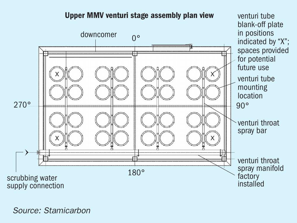
The primary function of the venturi stage (Figure 3) is to capture any residual sub-micron particulates – including condensable constituents and aerosols – that have carried over from the quench stage. It is the first section of the MMV scrubber vessel that treats granulator exhaust gasses as they exit the cross over duct. The venturi stage consists of:
- A solid diaphragm with mounting locations for 32 venturi tube assemblies – with 28 venturi tubes initially installed at the DGC plant
- Eight factory installed throat spray manifolds
- Four venturi throat spray bars.
The venturi tubes – which are mounted in parallel – are highly efficient at particulate collection. They function by creating a large velocity differential between the water (injected by sprayers) and the particulate laden gas stream. The exits to these tubes, by recovering the velocity pressure, are also designed to minimise fan energy requirements.
Each venturi tube assembly consists of a:
- Mounting plate
- Inlet cone
- Throat
- Low energy loss outlet diffusion cone assembly
- Throat spray nozzle connection
- Outlet deflector plate.
A spray of water is introduced into the centre of the throat of each venturi tube – in a counter direction to the gas flow – from a factory-installed throat spray bar. Water supply is modulated via a throat spray pump using a variable frequency drive (VFD). This maintains the pressure drop across the venturi stage – thereby ensuring high scrubbing efficiency – under varying operating conditions. Generally, pressure drop across the venturi stage will fall if gas flow decreases, unless more water is added.
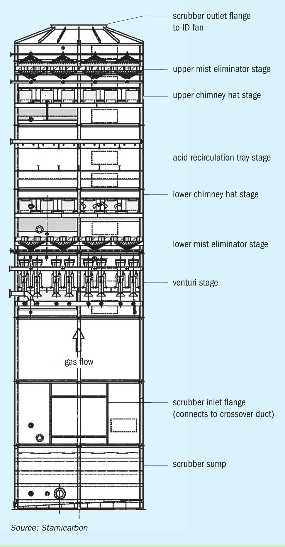
The lower mist eliminator (ME) stage is located above the venturi stage. Its main function is to keep the water in the venturi stage and prevent its carryover to downstream stages. The bottom (upstream) side of the ME chevrons are continually rinsed using irrigator sprays to help stop urea build-up.
The lower chimney hat stage is located above the lower ME stage. The chimney hat stage prevents the acidic solution recirculated in the upper stages from draining into the recirculated dilute urea solution in the lower stages.
Above this is the acidic recirculation tray stage. Gas phase ammonia, not captured in the previous stages, is scrubbed in this stage and converted to ammonium sulphate (AS) using sulphuric acid solution. This stage consists of dual orifice impingement trays arranged in two levels. Scrubbing water dosed with sulphuric acid is continually recirculated over the top of these trays via the AS solution vessel. Process gasses are forced to pass through recirculated AS solution via small perforations in these trays. The AS solution is concentrated and bled off to storage where it is collected for resale by an AS crystallisation unit.
The upper chimney hat stage, installed above the acid recirculation trays, has two functions. Firstly, it prevents AS droplets from entering the next stage and, secondly, it prevents recirculated demister water (ME spray water) in the upper stages from draining into the recirculated AS solution in the lower stage.
The upper chevron mist eliminator (ME) forms the uppermost stage. This array stops any water entrained in the gas stream during the acid recycle scrubbing stage from carrying over to the ID fan and stack. Irrigator sprays rinse the bottom (upstream) side of the chevrons to prevent particle build-up. These are controlled with an on/off block valve. The chevrons are also backwashed intermittently from above using the ME backwash spray bars. Washing ensures the proper drainage of captured particle-laden droplets under all operating conditions.
The MMV scrubber system incorporates six pump stations to circulate the various scrubber water sources. Each station consists of an operational pump and a standby pump. Pumps are needed to ensure that the spray nozzle design pressures and flows are being met. They are installed in parallel with common inlet and discharge piping. Each pump train consists of an inlet simplex strainer, discharge check valve and pressure gauge, plus inlet/outlet isolation valves for equipment maintenance.
THYSSENKRUPP
Urea plant revamping for cost savings and energy optimisation
Success factors
A successful revamp involves close coordination between the plant owner, the technology provider, and engineering and construction companies. This makes plant modernisation a major task.
In many ways, the modernisation of an existing urea plant is much more challenging than building a new plant – especially in terms of the design and subsequent project implementation. In most cases, construction space is limited and other plants found in close proximity must remain operational. The shutdown period for the urea plant itself must also be minimised and the timing of the revamp chosen carefully due to operational integration with other units. Modernisation projects therefore need to be kept on a short time schedule with no overruns if they are to avoid incurring excessive costs.
Case study
A recent revamp project at an ammonia-urea production plant in the Middle East and North Africa (MENA) region faced many of the above challenges. The three main objectives of the project object were to:
- Increase plant operating capacity by 25 percent
- improve product quality
- Reduce gaseous and liquid emissions to meet with new environmental regulations.
Background
The original plant was commissioned in 1998 and employs Uhde, Stamicarbon and Hydro Agri technologies – for ammonia synthesis, urea synthesis and urea granulation, respectively. The urea plant has a nameplate capacity of 1,700 tonnes/day and a design capacity of 1,925 t/d. The optimisation of equipment and operating practices has enabled the plant to achieve capacities of up to 2,000 t/d under optimal climate conditions.
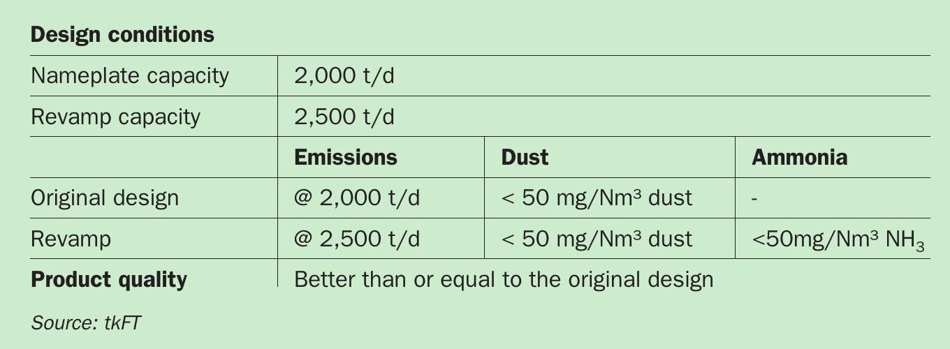
When the plant was designed, statutory requirements allowed the granulation unit to operate without an emissions reduction system for ammonia, and therefore only impingement-type dust scrubbers were installed.
Increasing plant operating capacity to 2,500 t/d was first proposed to the owner in 2009 by thyssenkrupp Fertilizer Technology (tkFT) and Uhde. The proposed project was, however, not pursued at that time due to the unfavourable economic situation.
More recently, a change in environmental regulations has required the enforcement of a new emissions limit for both ammonia (NH3 ) and dust of 50 mg/Nm³ at the plant. Because of this, the owner decided to look again at the revamp project for the plant and explore the options. Recent urea price increases and urea supply shortages were also deciding factors.
On behalf of the owner, tkFT developed a new revamp concept to increase the capacity of the urea fluid bed granulation plant. This updated the original revamp option by incorporating experience gained since 2009 as well as new developments in equipment capacity and design. The basic design data for the revamp is shown in Table 1.
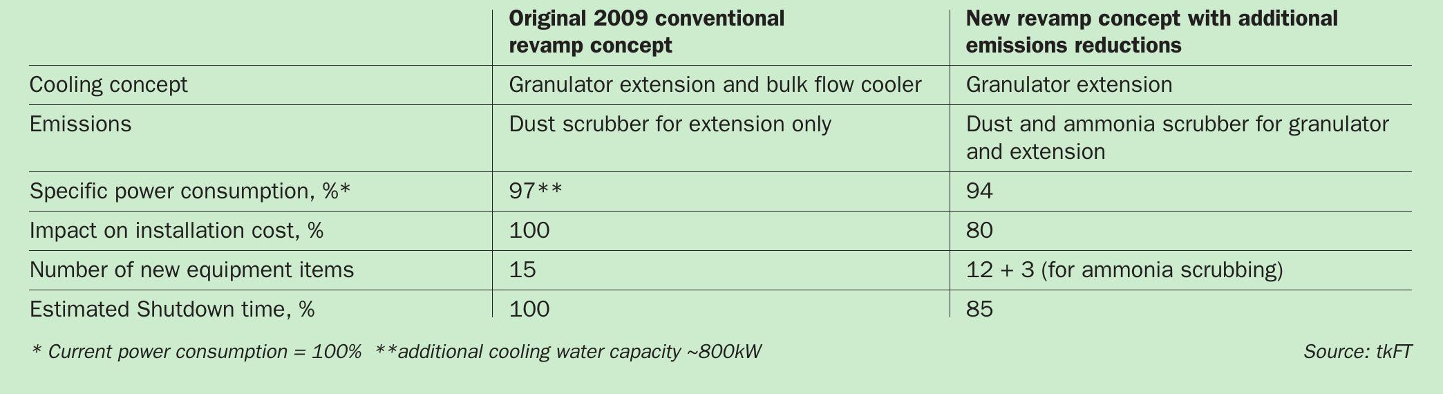
This new up-to-date concept is designed to make the plant future proof. It reduces investment costs and significantly decreases the plant down time required for project implementation. Additionally, the new concept introduces reduction measures for dust and NH3 emissions which were not part of the original 2009 concept. The main differences between the two revamp concepts are shown in Table 2.
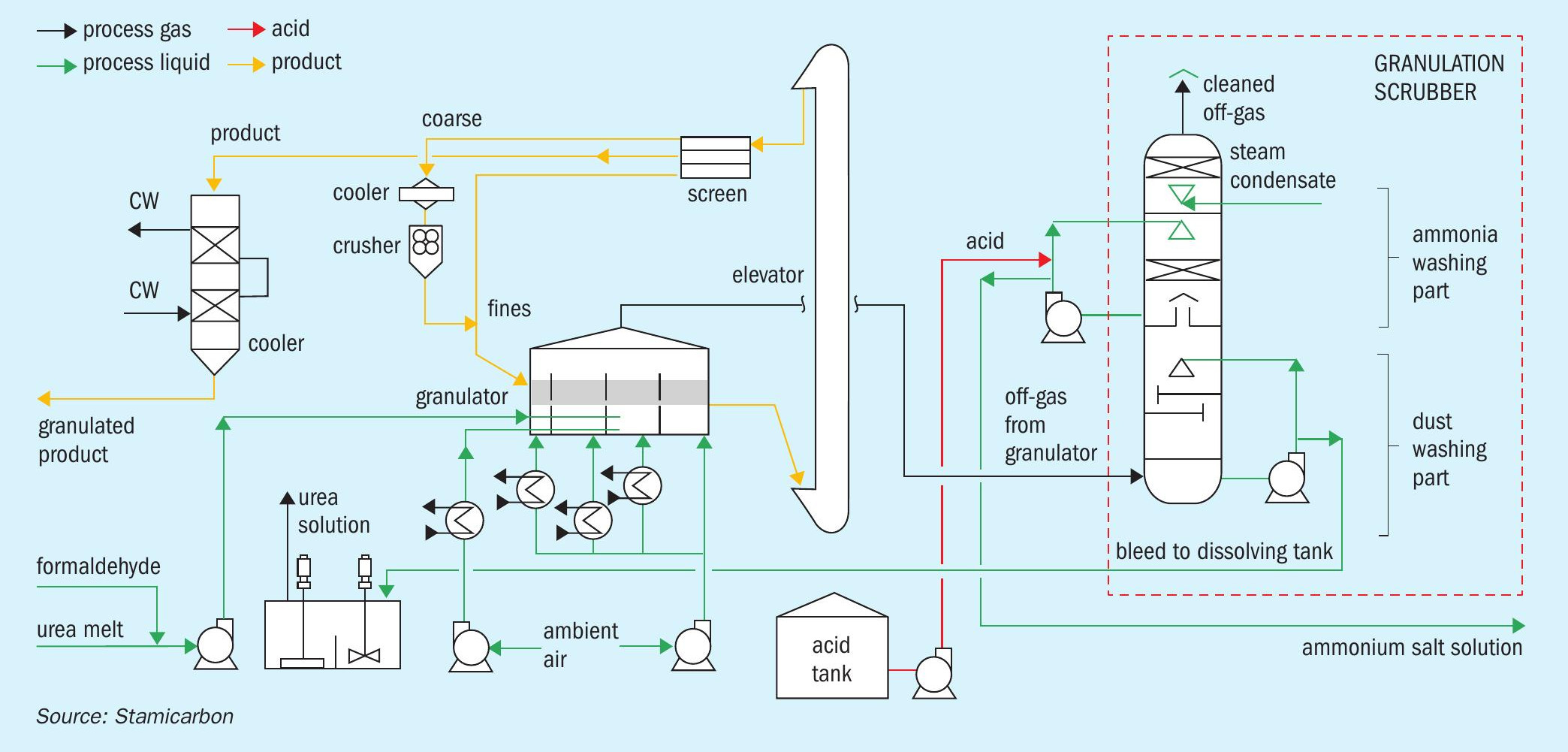
Revamp concept for a UFT® fluid bed urea granulation plant
Increasing capacity as part of the revamp inevitably raises heat input into the granulator. Additional cooling for fluidised bed granulation must therefore be provided to maintain the heat balance and temperature profile. This in turn increases the required ambient air flow to the granulator.
Significant improvement to the existing off-gas scrubbing system were therefore necessary to accommodate the higher air flow and the new, more stringent emissions limits. These changes were needed because the granulator’s existing dust scrubber was not able to clean the combined air stream from the granulator and the newly fitted granulator extension to the new, more stringent limits. The installation of a new granulator scrubber that could satisfactorily reduce dust and ammonia emissions was therefore needed. Importantly, this new scrubbing system had to be able to fit into the available space on site!
Emissions reduction
tkFT designed a two-stage horizontal scrubbing system for the revamp project, based on its recent experience in other granulation plants1, 2, 3 . This new type of low pressure drop scrubbing system is capable of reducing both dust and ammonia emissions from the granulator and the granulator extension to the required limits (Table 1).
Valuably, the new scrubber is also able to process waste gas streams from the urea synthesis unit – these containing ammonia – and reduce the load of the water treatment section by using ammonia-contaminated process water from other units. The routing of ammonia off-gases to the new scrubber is shown in Figure 1.
Another key feature of the new tkFT scrubber is that it can fit into the space occupied by the original dust scrubber.
This is despite it having to:
- Firstly, process a much higher airflow
- Secondly, reduce both dust and ammonia emissions.
Remarkably, this scrubber does not require any significant modifications to the existing steel support structure!
tkFT’s horizontal scrubber is highly cost efficient. For a 2,500 t/d capacity plant, the cross-sectional area is 50 percent less than the area of a standard tray-type scrubber for the same plant. This is possible because the scrubber’s internal configuration and mechanical design can be easily adapted to match actual needs. By consisting of fewer items of simplified equipment, it also cuts equipment costs. The pressure drop across this type of horizontal scrubber is also far lower than a comparable tray-type scrubber – even with the resulting higher gas velocity. The acidic scrubbing stage does, however, require additional circulation pumps and an intermediate tank.
Optimised emissions control within the plant complex requires proper handling of:
- Off-gas from urea synthesis or other units (Figure 1)
- Waste streams containing ammonia water.
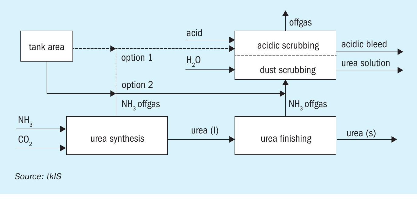
Off-gas from urea synthesis
The synthesis unit of the urea plant emits gaseous ammonia which needs to be treated. This is in addition to the urea dust and ammonia vapour emissions typically associated with the granulation unit.
The ammonia present in synthesis unit off-gas can be removed by fitting a standalone acidic scrubbing system. This typically consists of: a scrubber installed in the steel structure of the synthesis unit, pumps located at ground level, associated instrumentation and piping. However, the installation of a separate, dedicated scrubbing system (and related equipment) is not necessarily required – if the plant also includes a granulation unit with an ammonia scrubbing system.
Although the characteristics of synthesis unit off-gas and the granulation unit off-gas differ, both gas streams can be routed to the granulation unit’s ammonia scrubber for treatment. While the synthesis unit off-gas has a much lower flowrate, compared to the granulation unit, its ammonia concentration is much higher. Ammonia flows can also be discontinuous, depending on the design of the synthesis plant.
In principle, there is the option to treat all the ammonia containing off-gas streams from the synthesis unit in the granulator ammonia scrubber – from the ammonia water tank or the urea solution tank, for example.
Waste streams
The wastewater treatment section is often another limiting factor during plant revamps. This is because additional ammonia-containing wastewater streams usually require the installation of extra, new treatment equipment to avoid problems with environmental permits.
This ammoniated water can, however, be treated in the granulator ammonia scrubber, as long as it is not contaminated with other components, as ammonia will be stripped by the high air flow and captured in the acidic section. The addition of water also reduces the amount of clean make-up normally required by the scrubbing system.
How much ammoniated water can be processed largely depends on the amount of ammonium salt generated via the ammonia-acid reaction within the scrubber. The use of nitric acid is ideal as this produces ammonium nitrate. This can then be combined with urea to generate the valuable liquid fertilizer urea ammonium nitrate (UAN) to supplement the volume already being produced at the plant.
In contrast, ammonium sulphate solution is created if sulphuric acid is used to capture ammonia instead. Low amounts of ammonium sulphate can be incorporated within urea fertilizer using tkFT’s Ammonia Convert Technology (ACT) system. However, ammonium sulphate must be exported if generated in larger amounts. This can then be used as feed for an NPK or ammonium sulphate (AS) plant. Alternatively, it can be crystallised and sold as fertilizer.
All of the above are interesting water treatment options which can significantly reduce the cost and operating complexity of a revamped plant.
Capacity increases
Increasing granulation plant capacity requires the installation of additional urea solution injection systems in the cooling section of the original granulator. These extra injection systems increase the heat input into the granulator, while reducing the available cooling area in the existing granulator.
To compensate for this loss of cooling area and increased heat input, an additional cooling section is necessary. This was achieved in the earlier revamp concept by positioning a bulk flow cooler between the granulator and the existing cooling system. This required a significant modification to the plant building.
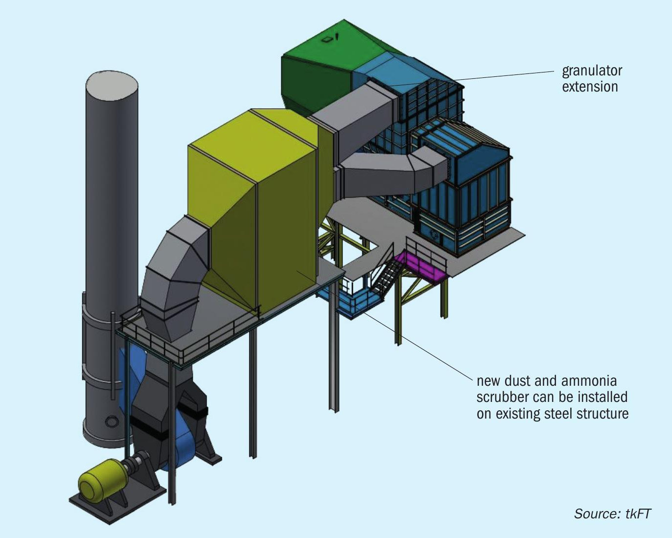
In the new concept, the extra cooling section is instead added as an extension to the granulator that incorporates its own dedicated air fluidisation system (Figure 2). This design achieves the maximum cooling possible by using all the available building area. These integrated granulator-coolers are already in operation at a number of tkFT plants.
Granulator extensions normally require an additional solid transport system to return the product from the new granulator outlet (via the safety screen) back to the existing fluid bed cooler inlet. However, for this project, novel product routing inside the granulator extension reduced the gap between the new granulator outlet and the existing equipment inlets from 10 metres to below two metres. This distance can be bridged by a simple chute, so avoiding the need for additional solid transport equipment.
The granulator extension design reduces the inlet temperature of granules entering the first fluid bed cooler. This then cools the product to the optimal temperature for screening and crushing operations without any modification. The product also exits the final fluid bed cooler at the required temperature – as its inlet temperature is also reduced. Overall, the new design means no additional product cooling is required (e.g., by the addition of a bulk flow cooler or an additional ammonia chiller) even through the granulator is operating at the new higher throughput and capacity.
The ability to reduce solid recycle temperature as part of the revamp had three added benefits by:
- Increasing product hardness. This significantly extends the operating intervals between cleaning by reducing scaling on product screens and roller crushers.
- Reducing bed temperatures in the granulation section. l Ensuring spare operational cooling capacity is available during high temperature ambient air conditions.
Screening capacity was also raised by replacing the original screens with four high capacity screens of the latest design. These fit into the existing building due to their compact size – whereas the previous concept required two additional screens supported by an extra platform.
Even with the new scrubber, the new revamp concept with a granulator cooling extension, as shown in Table 2, requires less equipment than a conventional cooling solution with an intermediate bulk flow cooler.
Summary
tkFT’s revamp concept for urea granulation plants is based on an optimised redesign of the existing granulator. In many cases, this significantly reduces the cost and time of the revamp by eliminating the need for additional cooling outside of the granulator.
Revamp projects now need to deliver much greater emissions reductions than in the past due to environmental regulations getting more and more stringent. Cost efficient revamp options are also required if plant modernisation projects are to remain economically viable. tkFT’s proprietary scrubber design – by integrating the granulation scrubbing system into the overall plant concept – makes both investment and operating cost reductions possible. The installation of less equipment during the revamp project also reduces plant shutdown time, avoiding substantial and costly production losses.
Authors’ note: tkFT has been the licensor for Hydro Agri urea fluid bed granulation technology since 2006.
References