Sulphur 406 May-Jun 2023
31 May 2023
Best practices for sulphur pipeline design
SULPHUR TRANSPORT
Best practices for sulphur pipeline design
As part of the expansion of the Shah gas plant (SGP) in the United Arab Emirates, a new 12-inch pipeline was designed and commissioned in January 2020. Hassa Al Mulla, Ravi Srinivas and Alsail Al Jaberi of ADNOC Sour Gas highlight the best practices implemented in the newly commissioned liquid sulphur pipeline.
ADNOC Sour Gas (ASG) Company is a joint venture between ADNOC and OXY. ASG owns and operates the Shah Arab Sour Gas Field, and Shah Gas Processing Plant (SGP). The Shah Arab Field produces ultra-sour gas (up to 25%
H2S and 10% CO2). The Shah plant, with a 21 km2 footprint, is located in the Liwa area, approximately 210 km south-west of the city of Abu Dhabi in the United Arab Emirates.
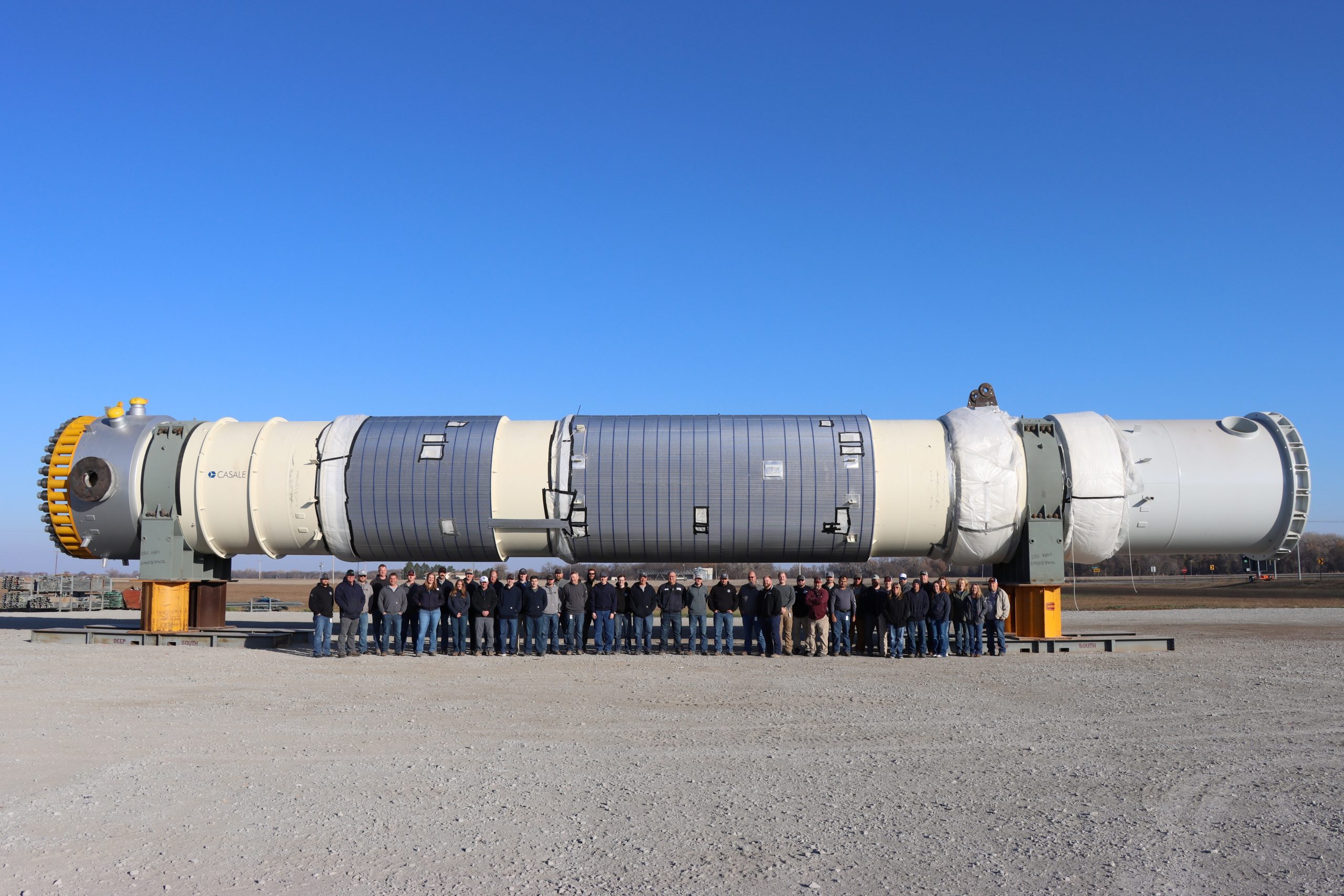
The Shah gas plant produces approximately 11,500 t/d of liquid sulphur via four trains of sulphur recovery units. The liquid sulphur is transported through 2 x 10,000 t/d capacity 12-inch skin effect electric tracing (SEET) pipelines from the main plant to the sulphur granulation station located approximately 7 km away. Liquid sulphur is then processed into solid granules, which are transported via train to the shipping terminal. As part of the expansion of the Shah gas plant a new 12-inch pipeline was designed and commissioned in January 2020.
Sulphur properties
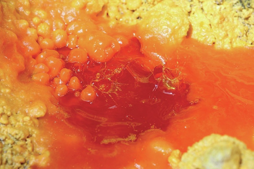
The transportation of liquid sulphur requires the temperature to be maintained between 130°C and 145°C. This is to avoid freezing which occurs at 119°C and to avoid the high viscosity form of sulphur which occurs at 158°C. Sulphur has a unique viscosity-temperature relationship. In the normal operating range (125-145°C) the molten sulphur colour is yellow. However, beyond 158°C, molten sulphur viscosity increases rapidly (5,952 cp at 160°C) and becomes difficult to pump. The molten sulphur colour at this point becomes dark red (Fig. 1). The optimum liquid sulphur pipeline operating temperature range is 130°C to 145°C.
The sulphur has an expansion ratio of 1:1.1, which means when sulphur cools, it reduces in volume and has a tendency to compact in pipeline low points. However, when remelting into liquid phase, it will expand rapidly within a few degrees of temperature increase which, in a closed vessel, is the mechanism for rapid pressure increase.
Sulphur pipeline design and best practices
The SGP sulphur pipelines are designed with expansion loops, located approximately every 200 m. In between the expansion loops, the pipeline has fixed anchor points. The movement of the pipeline from thermal stresses is permitted between anchor points. These anchor points located between expansion joints are specially designed to withstand the forces from normal thermal expansion while minimising heat losses from the system. The balancing of these two design criteria is well known throughout the sulphur transport industry as an important consideration whenever a system is designed, to minimise the chance of solid formation in pipeline systems.
It was recognised early on during the project design that re-melting of a frozen sulphur pipeline is a very complex operation, and that it is important to address certain design concerns such as:
- ensuring adequate and uniform heating across the pipeline;
- minimising heat losses at anchor points and SEET cable power boxes;
- ensuring temperature monitoring throughout the pipeline; and
- guaranteeing adequate reliability of the electrical supply and steam supply to keep the sulphur from freezing during an unexpected power outage.
A SEET pipeline “freeze and re-melt performance test” is typically part of the pipeline contractual warranty requirements.
The SEET system design capacity covers both the smaller heat losses during normal operation, and the larger loads required to re-melt if the pipeline freezes during an extended loss of power, such as a substation power outage.
Both normal and re-melt scenarios were part of the FEED design, and accordingly a SEET system was designed which gave the option to heat at low or high power in different segments. This is important because the power requirements during normal operation and re-melting are quite different.
The following sections highlight best practices.
Uniform heat loss
The most important factor in designing a sulphur pipeline to be easily re-melted is to ensure uniform heating of the solid sulphur throughout the pipeline. The best way to ensure this is to verify that the pipeline has uniform heat loss in all locations. The most important areas for this are:
- pipeline anchor supports;
- SEET power boxes and end boxes.
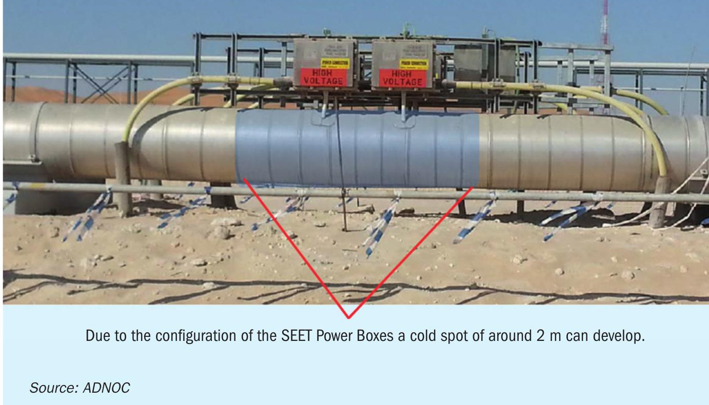
The design and application of the anchor supports and SEET system contributes to the vulnerability and sensitivities in a pipeline during the re-melt process. Anchor points and SEET transition points can be considered ‘cold points’ resulting in uneven melting which can result in sections of the pipeline melting while other sections are still solid. This can lead to an extreme build-up of high pressure.
In the design phase of the pipeline, a finite element analysis (FEA) should be carried out to verify the heat loss throughout the pipeline is uniform, including anchor points. This allows the designer to ensure potential heat loss points are identified and eliminated (Figs 2 and 3).
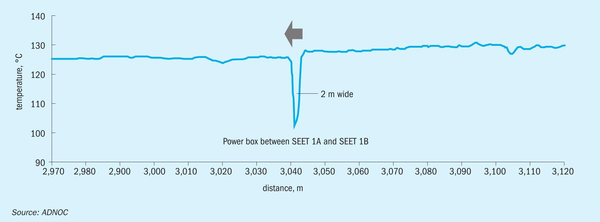
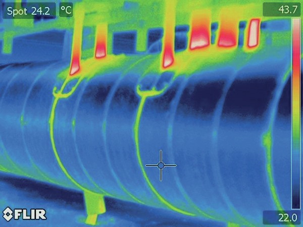
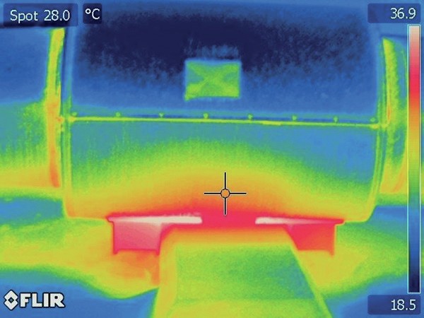
The heat trace design at SEET power junction boxes and the supports of the boxes should be designed in a way to ensure uniform heating to avoid uneven heating throughout the pipeline, specifically at power boxes and end boxes (Fig. 5).
Pressure build-up
The design of a sulphur pipeline should allow sufficient allowances for expansion and/or pressure build-up during re-melt procedures.
During the design of sulphur pipelines, there should be consideration for the high pressure in the pipeline, as well as the stresses and strains that occur during remelting.
Topography and distance
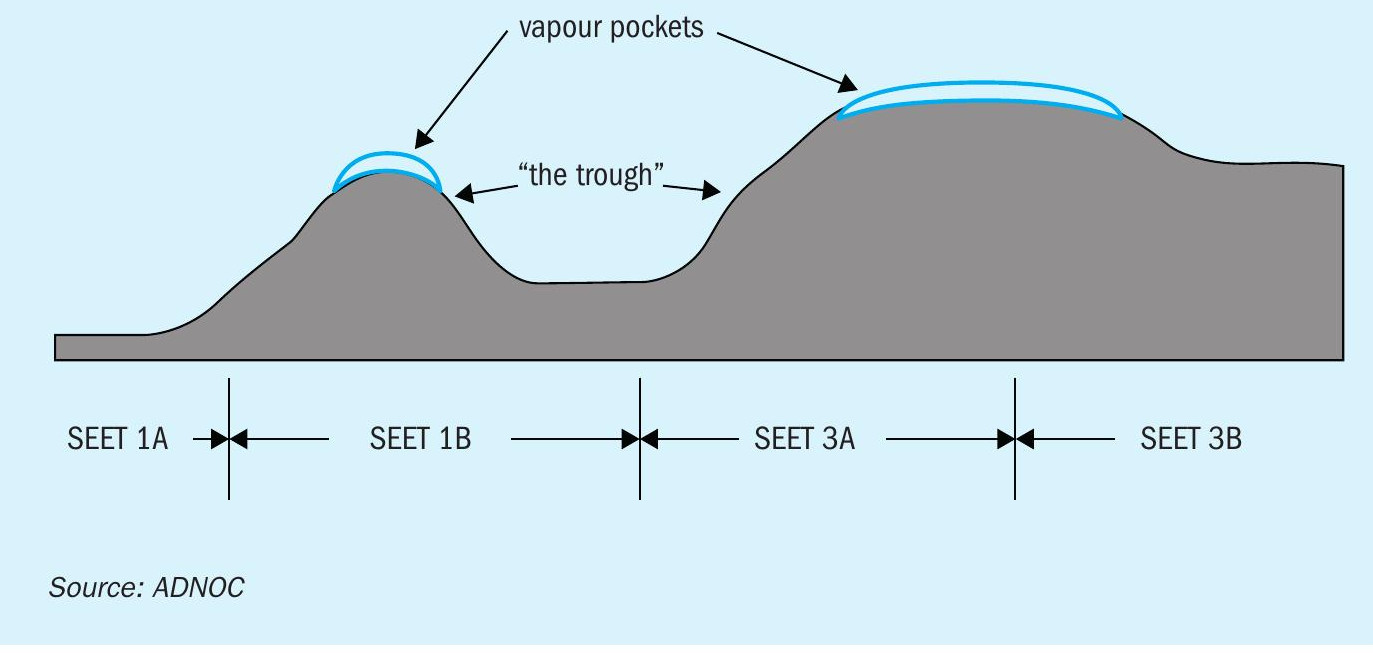
The length and vertical profile of the pipeline are both contributing factors to the unique complexity and operation of a sulphur pipeline. The undulating pipeline topography presents two issues (Fig. 6):
- the potential for the formation of vapour/air spaces at high points which can cause uneven heating (due to piping not being full);
- the liquid filling of “troughs” where the pipe is 100% full of sulphur at low points, which subsequently must be re-melted with no vapour space to expand into.
The extended length of the pipeline can result in having multiple SEET transition points hence having more than one cold spot. In addition, it increases capital and operating costs. If possible, reducing the pipelines length would be beneficial in the long run.
Re-melt procedure and monitoring of temperature profile
It is extremely important to monitor the continuous temperature profile of the sulphur pipeline as it is being heated in preparation for re-melt and during the melting period. The best tool for this is a distributed temperature sensing (DTS) system, a fibre optic system installed along the length of the pipeline. The DTS system includes a temperature evaluation module along with high and low temperature alarms, indication of colder points in the pipeline as well as any areas which may be heating too fast. The resistance temperature detector (RTD) installed for the SEET system are not adequate for this since they are only installed in specific locations and are used for general heating.
It is important to have experienced personnel monitoring the temperature profiles of the system in real-time to be able to identify temperature gradients in the system and take appropriate actions (Figs 2 and 5).
New sulphur pipeline – key features
For the new pipeline, it was important to follow the best practices in sulphur pipeline design, and to ensure that reliability and high-risk issues were addressed. The following features were incorporated into the new pipeline accordingly:
- Anchor design: The anchors were designed in such a way to ensure the same heat loss as the main pipe sections. This minimises the chance that there will be unmelted solid plugs during a re-melt and will also provide a longer period before solidification will occur.
- SEET power box: The SEET power box connections were designed to provide more uniform heating and to remove the box supports from being in direct contact with the pipe. This addresses both heat input and heat loss discontinuities.
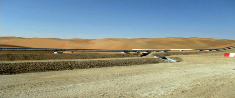
- Pipeline elevation: The pipeline was raised about 1 m above the nominal profile to minimise the chance for sand accumulation along the pipeline (Fig. 7). If sand encroaches on a sulphur pipeline, it can restrict the normal thermal growth and free movement of the pipeline, as well as causing hotspots due to over-insulation.
- RTD location: The location of the fixed temperature measurement devices was selected to ensure no RTD was located in an area where vapor could accumulate. This gives more accurate temperature measurement and better control.
- Vents and drains: The new pipeline is equipped with multiple drain pits and with vents at each of the high points. This will allow for draining of the pipeline in the event of an extended power failure or freezing event. The drain valves and drain piping are equipped with heating cables so that a portable generator can be connected in case of a power trip.