Sulphur 406 May-Jun 2023
31 May 2023
Impact and mitigation of processing bio-feeds in a refinery
PROCESSING BIO-FEEDS
Impact and mitigation of processing bio-feeds in a refinery
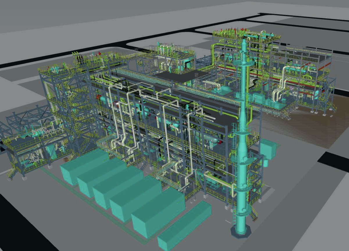
The production of renewable fuels by retrofitting existing refineries and their infrastructure is witnessing exponential growth. The impact on the existing amine, sour water and sulphur recovery units is inevitable. Based on several case studies, Marco van Son, Shashank Gujale and Tammy Chan of Worley Comprimo discuss the various options available to holistically review the sulphur block to determine the impact and mitigation of processing bio-feed.
The production of bio- and renewable fuels is a fast-growing market. The increase in the use of these products is mostly driven by government incentives and mandates. Petroleum reserves are depleting and there is greater public awareness of climate change initiatives regarding global warming and limits on greenhouse gas (GHG) emissions. In the US, according to the US Department of Energy Renewable Fuel Standard (RFS), transportation fuel sold in the US must contain a minimum volume of renewable fuels. Oil refiners and gasoline and diesel importers are subject to the RFS. Significant fines are imposed for failing to meet RFS requirements.
Bio- and renewable fuels are made from recently living but dead plant materials and animal waste (biological material) and considered a renewable resource. On the contrary, fossil fuels are decayed plant and animal matter that died millions of years ago, hence non-renewable. Note that biodiesel and renewable diesel are biofuels, but they are not the same! They are produced in very different processes.
Biodiesel is made in the process of transesterification of oils and fats, which forms fatty acid methyl ester (FAME). FAME can lead to problems with corrosion when blending with other diesel pools as well as stability and decomposition issues. As a result, many car manufacturers have limited the amount of FAME that can be present in the diesel used in automobiles to 2 to 20% of diesel fuel by volume. Hence biodiesel is usually blended in with petroleum products designated as Bxx, where xx is the percent by volume of biodiesel in a gallon of fuel where the rest is No.1 or No. 2 diesel, kerosene, Jet A, JP8, heating oil or any other distillate fuel. Pure or neat biodiesel is B100.
Renewable diesel, also called green diesel, drop-in biofuel, or hydrogenated vegetable oil (HVO), is made by an altogether different pathway via hydrotreating, gasification, pyrolysis and other biochemical and thermodynamic technologies of biomass. It is functionally identical to petroleum fuels and fully compatible with existing products. The production of renewable diesel does not result in the formation of FAME, so it can be blended without restriction. Also, catalytic hydroprocessing is flexible in accommodating a wide variety of biomass such as: raw vegetable oils, waste cooking oils, animal fats, algal oils, products from solid biomass processing, and pyrolysis oils. Renewable diesel meets ASTM D975 specification for petroleum diesel. In addition, renewable diesel meets required CGSB, and EN standards for diesel fuels.
Because renewable diesel is made from “less raw” biomass, waste and residuals from actual crops, it has a low carbon intensity (CI). CI is a measure of lifecycle emissions from extraction or growth, refinement, distribution, storage and combustion, and is reported as grams of carbon dioxide (CO2 ) equivalent per megajoule (MJ) of energy. Renewable diesel made from the aforementioned byproduct feedstocks can be in the range of 22-25 g CO2 /MJ depending on the specific feedstock. By comparison, petroleum diesel has a CI about five times higher (CI=102). Renewable diesel produced from crops such as soybeans can have twice the CI (CI=53), as the CO2 emitted from growing soybeans must be included in the CI calculation.
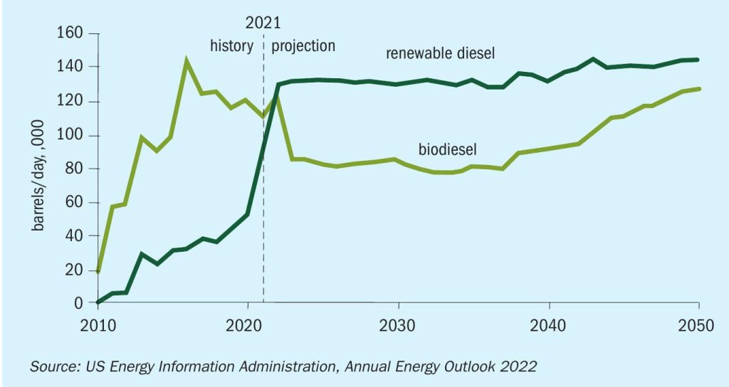
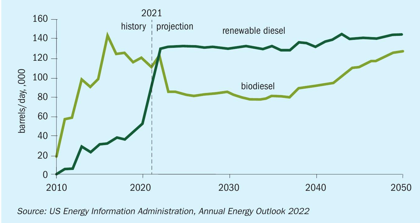
In recent years, the integration of renewable diesel facilities with the existing infrastructure of refineries has proven lucrative and numerous such renewable fuels projects are in various phases of operation, engineering or construction. The US Energy Information Administration (EIA) projects that renewable diesel supply will exceed that for biodiesel as shown in Fig. 1. Refineries can introduce hydrotreating of biofeed stocks through co-processing, complete conversion from fossil fuel feedstock, and/or grassroots installation.
Options for producing renewable fuels in refineries
Refineries seeking to produce renewable diesel can do so by co-processing, plant conversion, and/or grassroots installation.
In co-processing, a portion of the feedstock to an existing hydrotreater or FCC unit is converted to a renewable fuel feedstock. Typical values of 10-20% of the total feed are chosen to minimise the required modifications to the existing units. The co-processing of renewable fuel feedstock in an existing unit means that the unit still produces similar products containing H2 S and NH3 , however due to the higher oxygen content of the renewable fuel feed stock and lower content in nitrogen and sulphur, the concentrations of these components to be processed in the existing amine and sour water strippers can be substantially different: decreased sulphur tonnage, increase in CO2 production but typically limited impact on the amount of ammonia. In addition, due to the presence of oxygen in renewable fuel feed stocks, which is not present in conventional hydrocarbon feedstocks, there will be potentially more sour water to handle. Alternatively, plants can also consider handling the “co-processing” of renewable fuel feedstock through the full conversion of a single unit in the refinery while maintaining conventional hydrocarbons in the rest of the units.
Another option could be to fully convert an existing refinery to process renewable fuel feedstocks or even install a full grassroots facility to produce renewable fuels. The terminology for these scenarios are conversion and grassroots facilities.
Due to the more pronounced impact on the sour components that need to be processed, grassroots/conversion projects require more complex studies of new technologies and their possible integration with the existing sulphur block compared to co-processing projects.
In general, the introduction of renewable fuel feedstock will have the following impact on existing sulphur complexes:
In the acid gas treatment (AGT), the amine system will experience an increase in the amount of CO and CO2 to be processed, forming corrosive salts, and changing the physical properties of the solvent, ultimately reducing the acid gas removal capability.
The long chain hydrocarbons in the renewable fuel feedstock can also increase the foaming tendency of the amine solvent. The acid gas feeds will also be leaner in H2 S with more CO2 , hence making low tonnage sulphur technologies such as Selectox, LO-CAT, and Thiopaq worth studying.
For the sour water stripper (SWS), the increase in sour water flow rate as well as an increase in CO2 concentration, may result in an exceedance of the capacity of the existing stripper. The existing SWS may need to be debottlenecked, with additional stripping steam leading to a higher overall energy demand. Additional sour water processing capacity may need to be installed.
In the SRU, the acid gas feeds will have significantly higher CO2 concentration and a higher ratio of sour water acid gas to amine acid gas.
The higher CO2 in the feed to the sulphur recovery unit may not only make it a capacity bottleneck but also necessitate several modifications to maintain sufficiently high temperature in the thermal reactor to destroy contaminants such as ammonia. Integrating the existing SRU/ TGTU for co-processing and conversion may be complicated to maintain existing emissions requirements.
The following case studies illustrate the impacts that producing renewable diesel through conversion has on the existing sulphur complex and show how different technologies can help address the additional and/or new process requirements.
Case study 1
A refinery conversion project based on processing 100% bio-feed resulted in new required total sulphur tonnage processing capacity of about 5% of the existing SRU/ TGTU trains’ nameplate capacity. The new amine acid gas flow rate was only 20% of the original design with only 15 vol-% H2 S compared to the original 75 vol-%. The project considered three options to process new lower and leaner amine and sour water acid gas rates, while meeting the emissions specifications:
- repurpose existing SRU/TGTU/incinerator trains
- technologies other than SRU/TGTU;
- install two new smaller SRU/TGTU/ Incinerator trains.
In order to holistically evaluate these three options, each option was looked at with respect to the ability to meet the environmental requirements, installation and operational costs as well as ease of implementation.
Repurposing of existing SRU/TGTU/ incinerator
The refinery had a total of five SRU/TGTUs, of which two were deemed possible candidates for the revised conditions after the conversion to renewable fuel feedstock. Each unit had a capacity of 141 t/d with the following original acid gas compositions:
- amine acid gas: 80% H2 S/9% CO2 ;
- sour water acid gas: 25.5% H2 S/4% CO2 /40% NH3 .
After full conversion of the refinery to renewable fuel feedstock, the expected total sulphur capacity was 7-8 t/d, which represented a 20:1 turndown for the unit on a capacity basis.
In order to determine the feasibility of repurposing the existing SRU/TGTU to process the significantly lower sulphur tonnage, the major equipment items were evaluated to:
- identify if any existing equipment is limited to process the low sulphur feed;
- recommend process and equipment modifications to maintain overall sulphur recovery efficiency.
Based on a separate analysis to optimise the upstream amine system including future CO2 capture, it was recommended to route the feed amine acid gas to the TGTU absorber which would act as the enrichment unit. The acid gas from the TGTU regenerator containing relatively higher concentration of H2 S would be recycled to the SRU front end where it would be fed to the main burner along with the sour water stripper acid gas.
Continuous natural gas co-firing was required to maintain a high enough temperature in the SRU thermal reactor to destruct the ammonia in the sour water stripper acid gas. The heat and material balance based on this continuous natural gas co-firing and iterative calculations using modified equipment (for example, plugged sulphur condenser tubes) was used for the equipment evaluations. The key findings are described below.
- In general, it was feasible to repurpose the existing SRU/TGTU with minor modifications to process the future low-capacity feed because of the renewable diesel conversion while meeting the SO2 emissions limit.
- The existing acid gas burner will need to be replaced as the required continuous natural co-firing rate is significantly higher than the original design.
- Natural gas co-firing is also expected to increase the quantity of COS and CS2 that needs to be hydrolysed in the first catalytic reactor to minimise the loss of sulphur recovery efficiency. Therefore, the first catalytic bed is recommended to be made up to 25% alumina catalyst at the top and 75% titania catalyst at the bottom to enhance COS/CS2 hydrolysis.
- Low gas throughput through the sulphur condensers can lead to sulphur fogging which has the potential to lower the sulphur recovery efficiency. Plugging of more than 70% of the tubes in the sulphur condensers is recommended.
- A metallurgy review recommended several upgrades to stainless steel material in piping or as lining to existing carbon steel vessels.
Non SRU/TGTU technology option evaluation
Processing the new bio-feed impacts the waste streams going to the SRU/TGTU as the hydrotreating unit will produce H2 S from the sulphiding agent and more sour water will be produced with small amounts of ammonia and CO2 . In order to find alternatives in case the existing SRU/TGTU could not adequately handle these changes, the following actions were taken:
- technical alternatives in lieu of SRU/ TGU were identified and evaluated;
- options for sour gas pre-treatment to remove NH3 and process H2 S only were evaluated.
The following configurations were evaluated as part of the study.
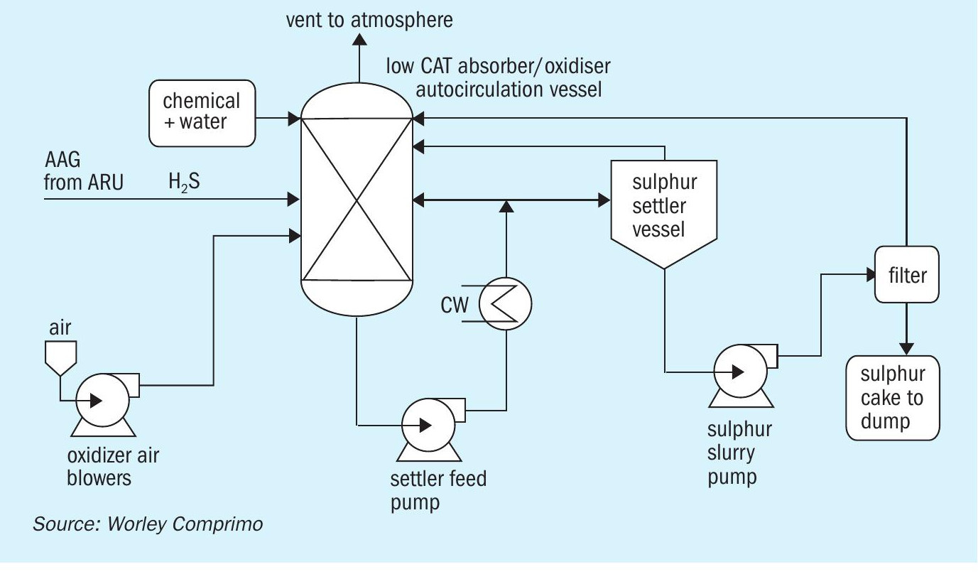
LO-CAT/Sulferox
The LO-CAT® process (Fig. 2) is a liquid redox technology that converts H2 S to elemental sulphur in an aqueous solution of iron with a proprietary blend of chemicals to enhance the catalytic performance of the iron. The Sulferox technology is similar. The H2 S is converted to elemental sulphur by the redox chemistry. The elemental sulphur is filtered from the solution as a 60-80 wt-% sulphur “cake”, depending on the filtration method and amount of water wash.
Pros:
- gas stream leaving the unit typically contains <10 ppm H2 S (if this meets the local emission standards, the treated stream can be vented to atm.);
- inherently safe aqueous solution.
Cons:
- produces poor quality sulphur;
- expensive chemicals used in the process and get consumed as some tend to be lost with sulphur product;
- chemical degradation, plugging and foaming are concerns with this process.
The conclusion regarding the option for a redox type technology was that the sulphur produced is not saleable and is typically sent to landfill, which made the technology less desirable as an option.
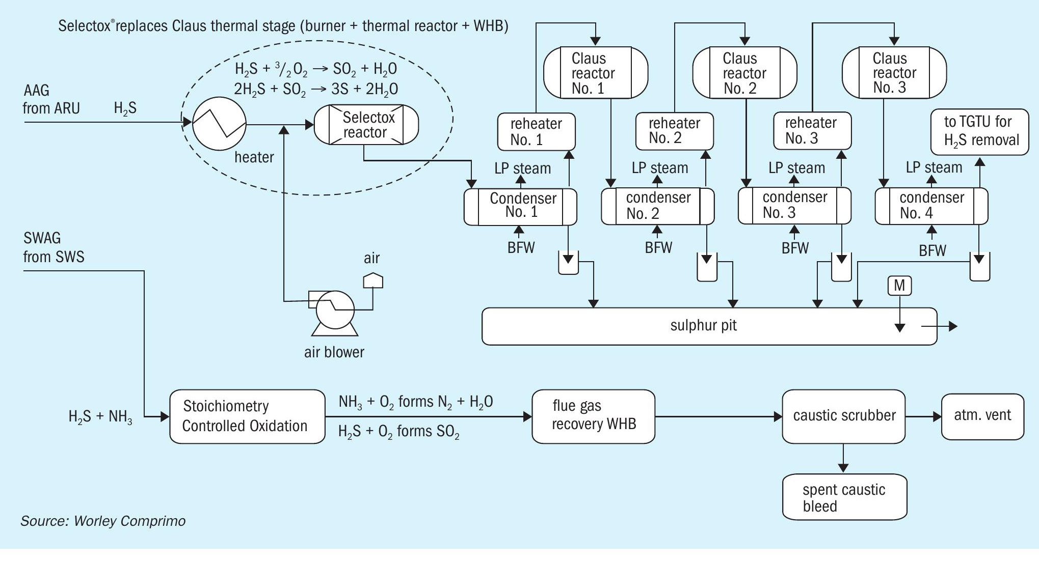
Selectox
Selectox® (Fig. 3) is a catalytic sulphur removal technology using catalytic stages only and no Claus thermal section. It can handle amine acid gas with low or no NH3 content and produces sulphur. The sour water acid gas containing H2 S and NH3 is sent to a stoichiometry-controlled oxidation (SCO) unit for NH3 destruction and complete combustion of H2 S. The flue gas is then cooled in the waste heat boiler (WHB) to recover energy by means of steam generation, which can be utilised for plant heating or other purpose. The flue gas from the WHB is then sent to a caustic scrubber unit to remove SOx by using caustic. The treated gas is then released to the atmosphere via the stack.
Pros:
- complete removal of H2 S (>99.9% efficiency);
- no fired equipment and eliminates fuel gas co-firing, air and acid gas pre-heating (opex);
- produces premium grade saleable sulphur.
Cons:
- can handle only amine acid gas and not ammonia containing sour water acid gas;
- SWAG from SWS will need additional capex/opex for the SCO incinerator and caustic scrubber.
The conclusion for the option to use Selectox with separate combustion of the sour water acid gas was that this option was not cost effective as it involved the capex for replacement of the Claus thermal stage and needs additional capex/opex for the SCO incinerator and caustic scrubber.
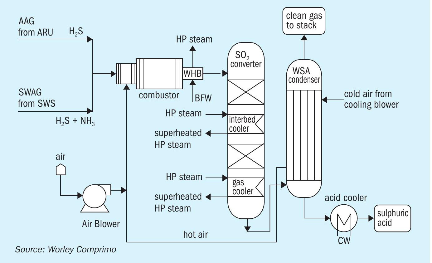
WSA (Wet Gas Sulphuric acid) technology
The Topsoe™ WSA technology (Fig. 4) is a wet gas catalytic process that turns sulphurous gases into commercial-grade sulphuric acid (typically 98% concentration). The H2 S in the feed is oxidised to SO2 by combustion and NH3 is destroyed in this process. Catalytic conversion of SO2 to SO3 takes place in the catalyst beds. The thermal energy given off by this reaction is recovered between the catalyst beds. After the last conversion step, the gas is cooled, and the SO3 reacts with water vapour to form gas-phase sulphuric acid. The process gas is cooled by a counter-current flow of air in the WSA condenser. Condensed commercial-grade sulphuric acid exits from the bottom of the condenser, where it is cooled and sent to storage and clean gas leaves from the top of this condenser to the stack.
Pros:
- produces commercial-grade 98% sulphuric acid and HP superheated steam for plant usage;
- can process both amine and sour water acid gas in one technology.
Cons:
- high capex;
- very low production of sulphuric acid due to the low sulphur loads.
The conclusion for the option to install a WSA unit was that owing to the limited quantity of the resulting sulphuric acid product flowrate due to a lean H2 S feed gas and the high capex involved for installation of the WSA unit, this option was not deemed attractive.
Thiopaq + WWT two-stage SWS
The WWT process is a two-stage sour water stripping process that separates NH3 and H2 S. The H2 S stream from the SWS (free of NH3 ) can be combined along with amine acid gas from the ARU and can be treated in a Thiopaq biological sulphur unit (Fig. 5). The Thiopaq biodesulphurisation unit contains self-regulating bacteria that convert H2 S to manageable solid elemental sulphur which can be used in agricultural applications. The vent gas from the Thiopaq unit is sent to incineration.
The NH3 stream will be sent to the SCO unit for ammonia destruction followed by a caustic scrubber. The flue gas is then cooled in the waste heat boiler to recover energy by means of medium-pressure steam generation which can be utilised for plant heating or other purpose. The flue gas from the WHB is then sent to a caustic scrubber unit to remove SOx by using caustic. This option provides good emission controlled with the addition of a caustic scrubber and a final polishing unit for SOx and any particulate removal from vent gas to the atmosphere.
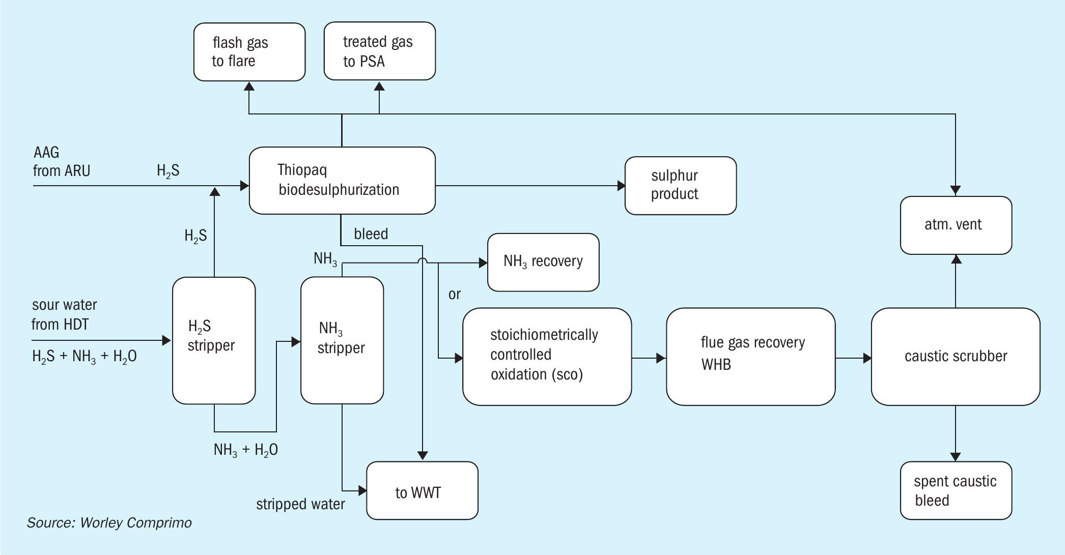
Pros:
- higher recovery of H2S from AAG/SWAG as premium grade sulphur product;
- proper integration of the SCO unit allows utilisation of the heat released by the combustion of ammonia, for steam generation and superheating purposes.
Cons:
- two-stage SWSs are more complex to operate and are not proven for lean sour water stream containing high CO2 ;
- higher capex due to additional NH3 stripper and additional incinerator and scrubber.
- no purpose for pure ammonia stream recovered from the NH3 stripper and requiring specialised incineration equipment;
- difficult market to produce pure ammonia with higher safety risks.
This option is not recommended because of the complexity of combining the sourwater and the off-gas treating unit. Also, additional capex is involved for NH3 stripper unit to remove NH3 from lean sour water acid gas stream containing very little amount of H2 S.
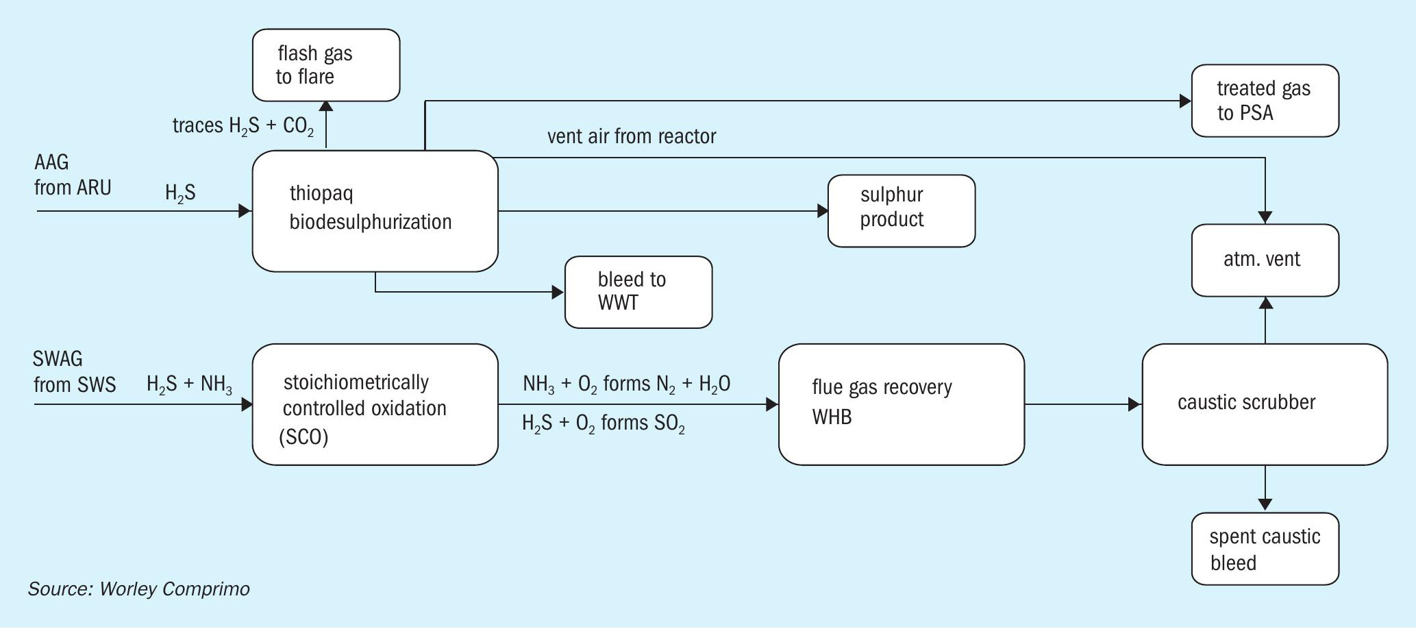
Thiopaq + SCO + scrubber
This is a slight modification of the above option that offers an advantage to line up the SWS unit independent of the ARU unit, by eliminating the two-stage SWS (Fig. 6). Thiopaq is retained for H2 S recovery from the ARU in this scheme.
Pros:
- eliminates the two-stage SWS and independent line-up of SWS unit and ARU unit;
- handles both H2 S and NH3 in the SWAG.
Cons:
- bleed caustic disposal is a potential issue though the low H2 S content in SWAG needs lower caustic circulation rate.
The SCO + scrubber can be a viable solution for processing SWAG if spent caustic can be easily disposed. Thiopaq seems viable for H2 S recovery as this technology has demonstrated that its sulphur product can be sold for fertiliser production.
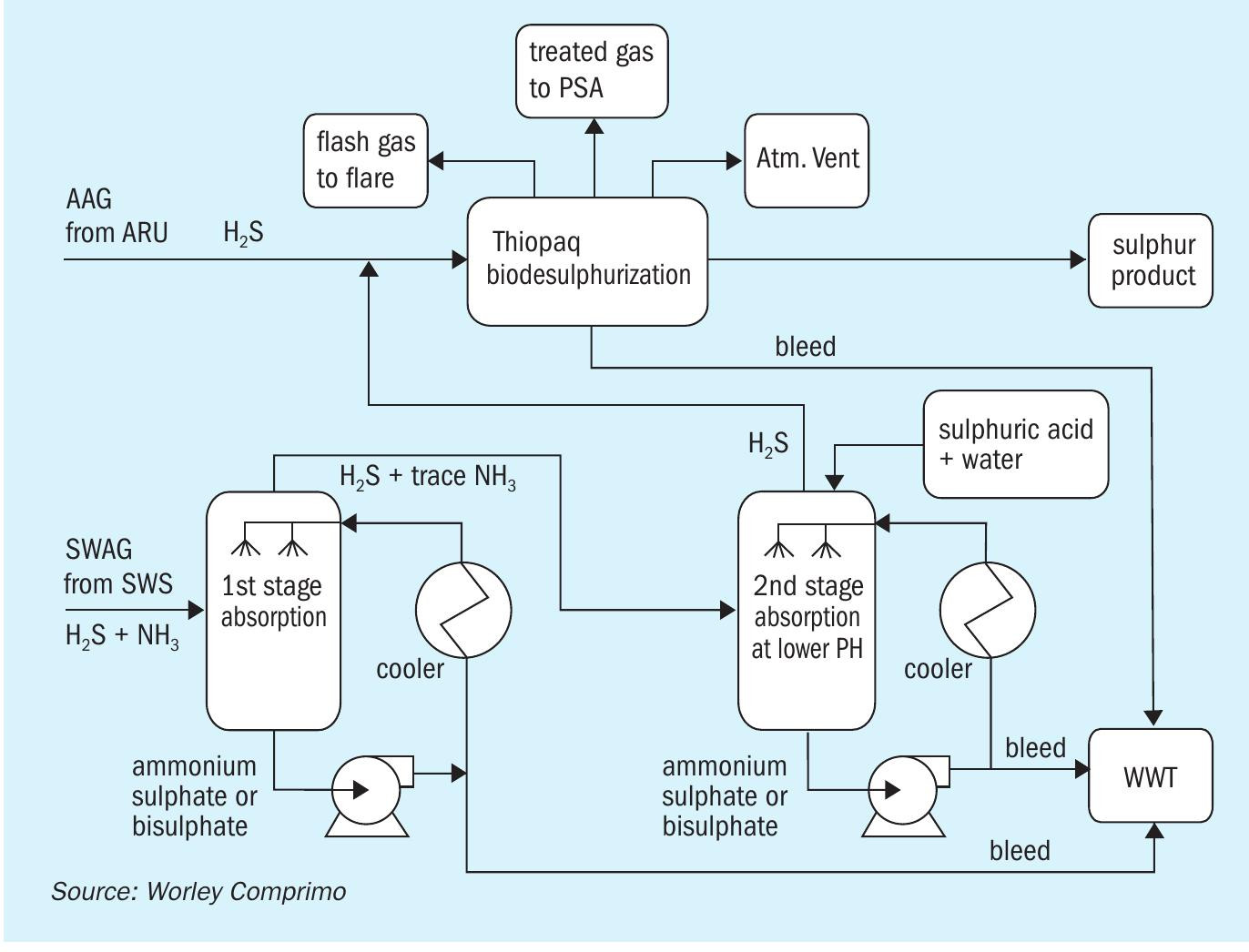
Ammonia acid wash + Thiopaq
The ammonia acid wash (NH3 scrubber) (Fig. 7) consists of a dual-stage absorption system designed to remove 99.9% of the ammonia from the sour acid gas stream. The SWAG from SWS enters the first scrubbing column. As the gas is slightly warmer than the operating temperature of the scrubbing column the gas is quenched to the adiabatic saturation temperature as it enters the column and contacts the diluted sulphuiric acid solution leaving the packing. The quenched gas then flows up through the column counter-current against a dilute sulphuric acid solution through a packed bed to remove the ammonia from the gas. Gas leaving the top of scrubbing column no. 1 enters the bottom of scrubbing column no. 2. Scrubbing column no. 2 is essentially the same as scrubbing column no. 1 but operates at a lower pH to ensure complete removal of the ammonia from the gas.
Scrubber pump no. 1/no. 2 continuously circulates the scrubbing liquor via scrubber cooler no. 1/no. 2 back to the distributor at the top of the scrubber columns no. 1/no. 2. Scrubbing solution pH and ammonium sulphate concentration is maintained by the addition of sulphuric acid and water to scrubber column no. 2. Because the sulphuric acid is added to column no. 2 only, the scrubbing solution in this column is more acidic (lower pH) which improves the ammonia removal and predominantly ammonium- bisulphate is formed in this column. At the higher pH in column no. 1 the ammonium bisulphate reacts with more ammonia to form ammonium sulphate.
After passing through the packing in scrubber column no. 2, the treated gas passes through a mist eliminator to remove any entrained droplets of scrubbing solution and is then sent to join the main amine acid gas stream entering the Thiopaq unit.
Pros:
- higher recovery of H2 S from both AAG/ SWAG as premium grade sulphur product;
- using the dual column approach ensures high ammonia removal rates while at the same time minimising the sulphuric acid consumption and the ammonium bisulphate concentration in the scrubber effluent.
Cons:
- disposal of the bleed ammonium bisulphate or ammonium sulphate.
This option was deemed viable if disposal of the effluents from the ammonia acid wash can be suitably resolved.
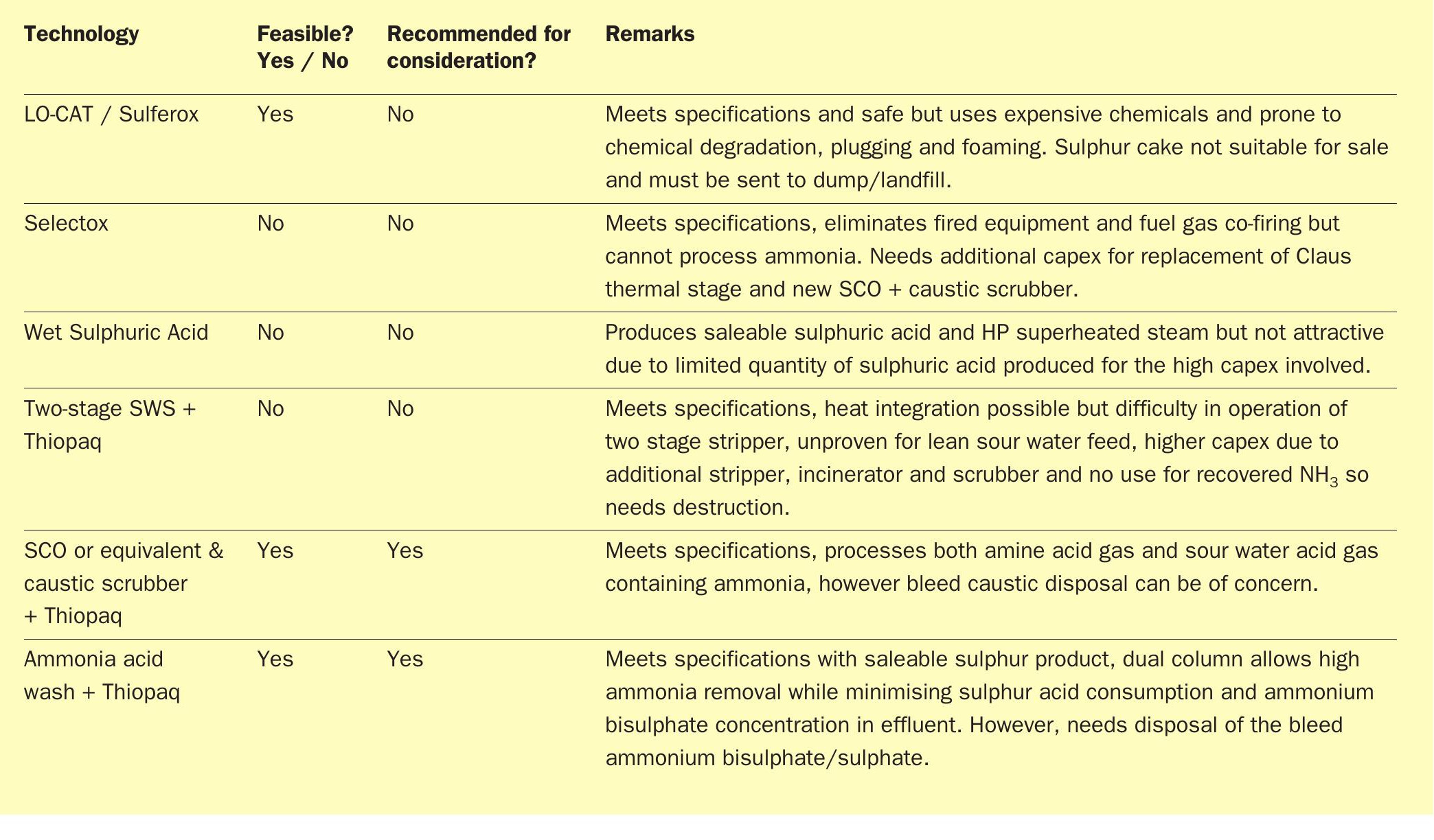
Technology evaluation summary
Table 1 provides a summary of the available alternative technologies in lieu of the SRU to process NH3 and H2 S in acid gas from the ARU/SWS.
New SRU/TGTU installation
The third option considered during the study phase was the installation of two fully redundant new SRU/TGTUs that would be designed for the new capacity resulting from the revised conditions in the amine and sour water systems. An N+1 configuration was necessary to maintain the emissions at all times to meet the regulatory requirements.
The installation of two new SRUs with TGTUs provides the benefits of new equipment designed for purpose and improved operability. It would provide a full spare as well as the ability to already plan for future expansion of the biofuels facility. It would require, however, operation of one of the two new units in hot-standby with the increased risk of sooting, equipment damage as well as corrosion.
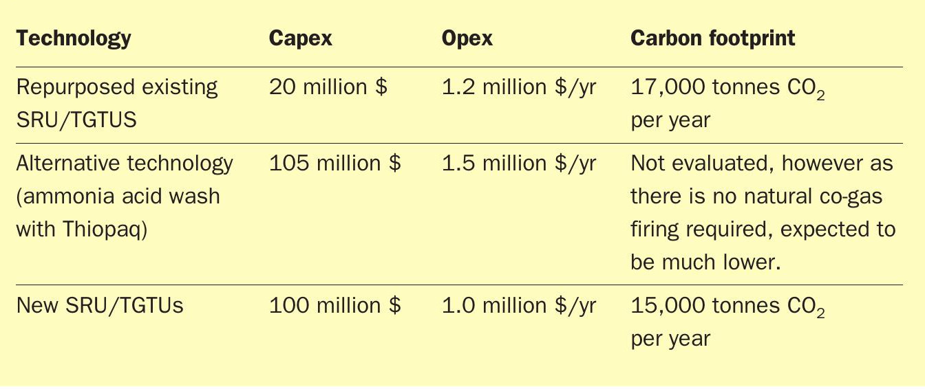
Comparison
The three options described above were compared with respect to capex and opex and the results are provided in Table 2.
Path forward
Based on overall capital cost, operating cost and carbon intensity comparison, the existing SRU/TGTU revamp options was determined to be favourable. The alternative technologies and the new smaller SRU/TGTU trains were not deemed economically viable, even though there may be some benefits in the alternative technology with respect to the total carbon footprint.
Case study 2
A refinery biofuels conversion project included a renewable diesel hydrotreater with a feed capacity of 9,000 bbl/d and hydrocracking capacity of 45,000 bbl/d. Sulphur production of the facility was around 50 long t/d prior to the full conversion to bio feedstock.
Hydrotreater recycle hydrogen must contain 200 ppmv H2 S to maintain catalyst metals in the sulphide state and thus prevent permanent over-reduction. The plant opted to do so by continuous injection of a sulphiding agent to avoid the capex and logistical complications of concentrated H2 S recycle, which would have reduced net acid gas sulphur to 0.6 long t/d.
Many attempts to somehow repurpose existing Claus facilities were considered and ruled out and a similar evaluation was done as provided in case study 1.
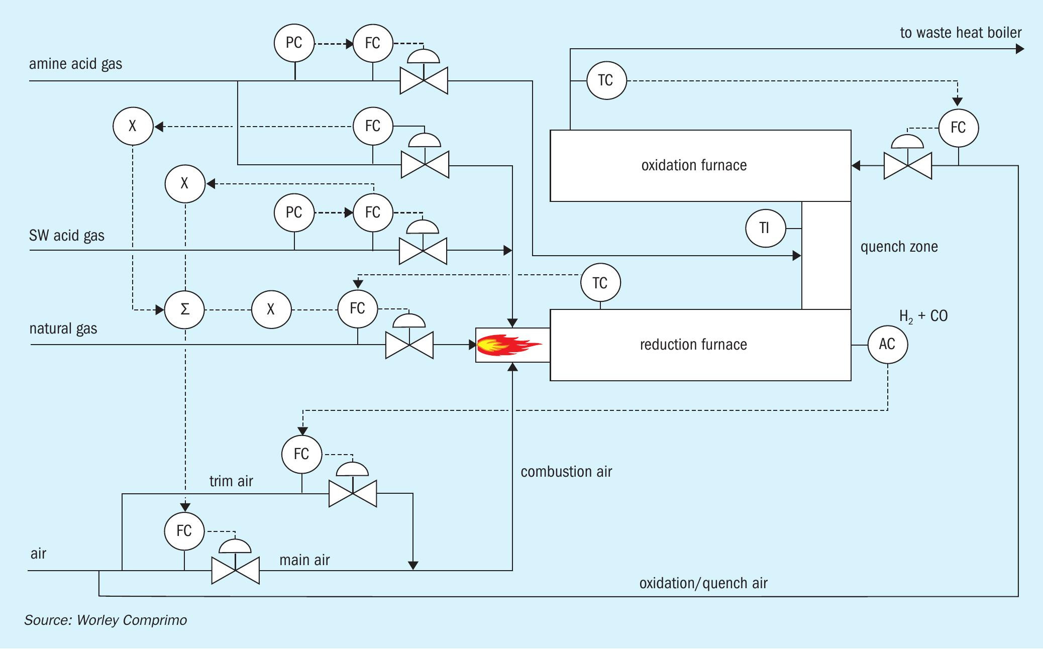
Ultimately, acid gas incineration of all the acid gas streams was chosen followed by caustic absorption of SO2 . SWAG is thermally oxidised under reducing conditions at a theoretical flame temperature of 1,315°C, followed by quenching with AAG to a minimum of 540°C to ensure subsequent thermal oxidation. As it turned out, at normal rates in the subject case, simulation predicted that bypassing the entire AAG around the reduction furnace quenched the effluent to 510°C. To ensure at least 540°C, some AAG was diverted to the reduction furnace, and cofiring increased to achieve 1,315°C. (Fig. 8)
Environmental regulations required a minimum thermal oxidiser temperature of 815°C to ensure virtually complete CO destruction. In addition, temperatures greater than 815°C would likely increase NOx, which the plant was under regulatory pressure to minimise. Excess quench air required to limit the thermal oxidiser temperatures to 815°C resulted in almost 10 mol-% residual O2 .
However, high percentages of O2 can have unintended punitive consequences in the likely event environmental regulations require correction of measured stack concentrations to X % O2 according to the formula in Table 3 where X will typically = 0 or 3:
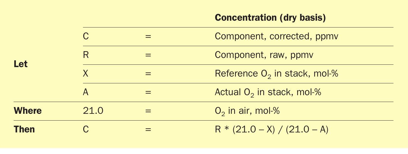
Stack emission concentrations measured at O2 concentrations greater than the reference value (0 or 3%) increase when corrected. At a reference value of 0% O2 , for example, 100 ppmv measured at 10% O2 equates to 100*(21-0)/(21-10) = 191 ppmv corrected. In a typical Claus thermal oxidiser, high O2 represents unnecessary dilution. In this case, however, it is a process requirement. That distinction should be made when negotiating environmental permit limits.
The oxidation furnace effluent is cooled from 815°C to 275°C by generation of saturated 45 bar steam in a kettle waste heat boiler. The need for selective catalytic reduction (SCR) of NOx was deemed unnecessary. Had an SCR been employed, cooling to 230°C would have been considered in order to minimise potential catalyst fouling with ammonium bisulphate.
Potential cooling is limited by the sulphuric acid dew point. Above 1,000°C, 1-5% of the SO2 will typically be oxidised by O2 to SO3 , forming sulphuric acid vapour (H2 SO4 ). While lower temperatures favour SO3 formation, the reaction does not readily occur below 1,000°C because of the high activation energy required, and it is thus assumed that the SO3 content is set by the equilibrium at 1,000°C, for which equilibrium correlations exist. Four different methods predicted dew points of 105145°C. Another literature source simply cites 175°C as a safe upper limit7 .
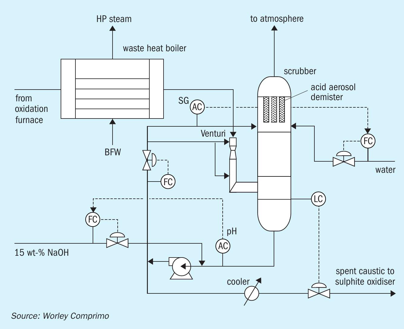
Hot gases are initially quenched with a recirculating caustic solution side stream in a venturi scrubber at the inlet to the packed column to prevent localised high temperature corrosion of column internals despite stainless steel (SS) construction. In this case both the venturi and scrubber were constructed of 316 SS. Fibreglass is a common alternative for the column shell, and brick-lined venturis are sometimes employed when there is greater incentive to minimise upstream cooling. Maximum recommended inlet temperature to a SS venturi is 340°C (Fig. 9).
Some sulphuric acid vapour will be absorbed in the venturi, but once the gas is quenched below the dew point, resultant acid aerosol mist particles lack the momentum required for efficient scrubbing upon impingement with caustic solution droplets. Counterintuitively, many thus pass unabsorbed through the scrubber.
Condensed sulphuric acid mist (SAM) tends to form a white visible plume upon discharge to atmosphere. Perhaps for this reason, it is often treated quantitatively as 10+ micron particle (PM10) emissions, despite the fact that acid mist particles tend to be sub-micron. In this case the plant had separate annual PM10 and SAM mass limits, where allowable SAM emissions were 100 x allowable PM10 emissions.
Specialised “candle filters” designed to rely on Brownian diffusion are located at the scrubber outlet to coalesce sub-micron SAM. Vendors claim up to 99.9% particulate removal with pressure drops of 10-20 inches H2 O. Fouling can be problematic if particulates tend to be sticky. Wet electrostatic precipitators (WESP) are considered a superior alternative if the additional cost can be justified.
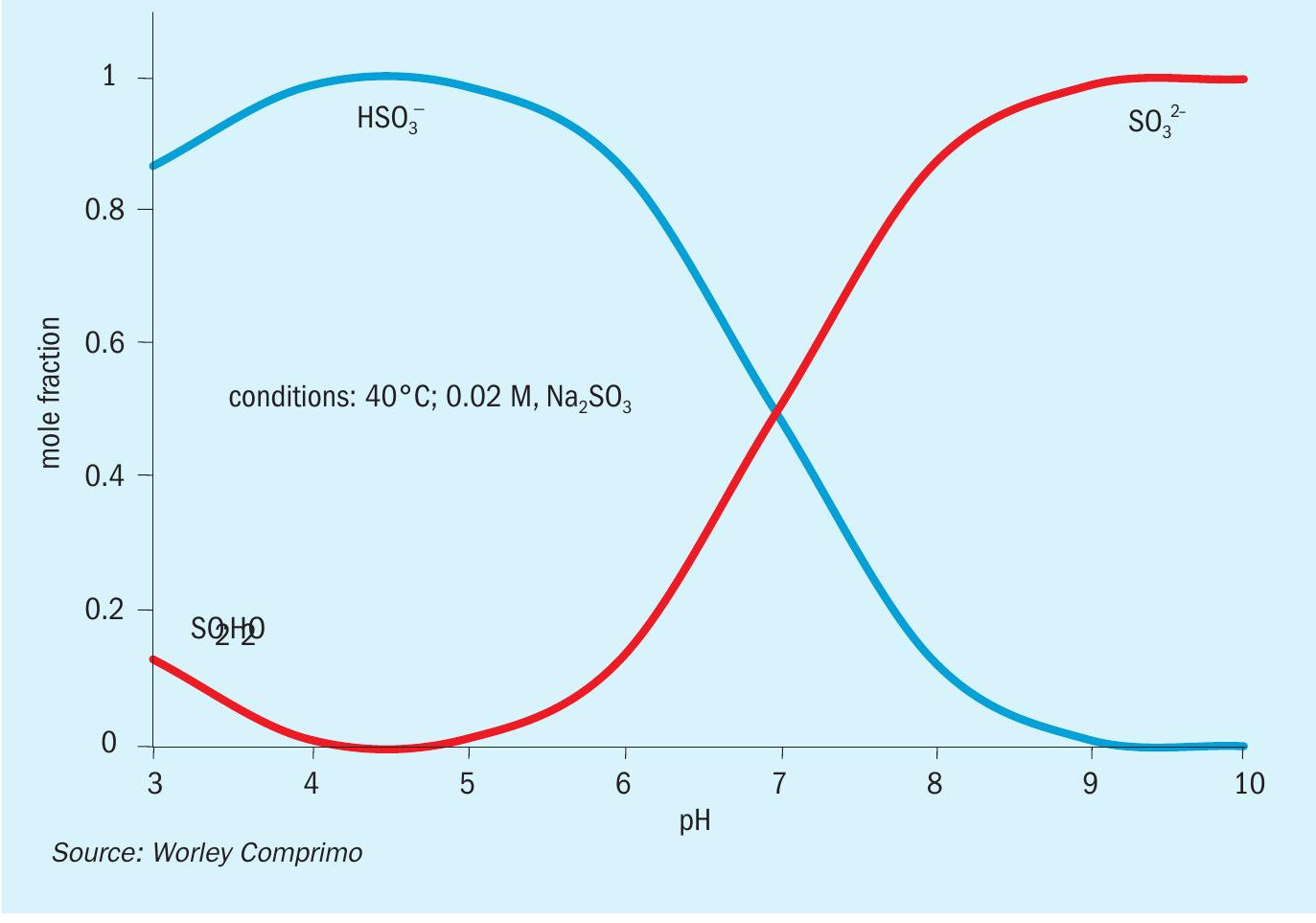
The circulating liquor contains the equivalent of 5-6 wt-% sodium hydroxide (NaOH), with roughly 85% as sodium sulphate (Na2 SO4 ) and the balance split between sodium sulphite (Na2 SO3 ) and sodium bisulphite (NaHSO3 ). Bisulphite/ sulphite equilibrium is highly buffered, making it relatively easy to maintain an optimum pH of 7-8 while absorbing negligible CO2 (Fig. 10).
In this case 15 wt-% NaOH is added on pH control, and water added separately to maintain a specific gravity of 1.08. It was decided to add the makeup water via a wash tray above the packed bed on the premise that knocking down entrained liquor may tend to reduce fouling of the candle filters. This does not appear to be normal practice, so the value in doing so remains to be seen.
In addition to being corrosive to carbon steel, sulphite/bisulphite have a chemical oxygen demand (COD) and must be oxidised to sulphate before discharge to the environment.
Grassroots facilities
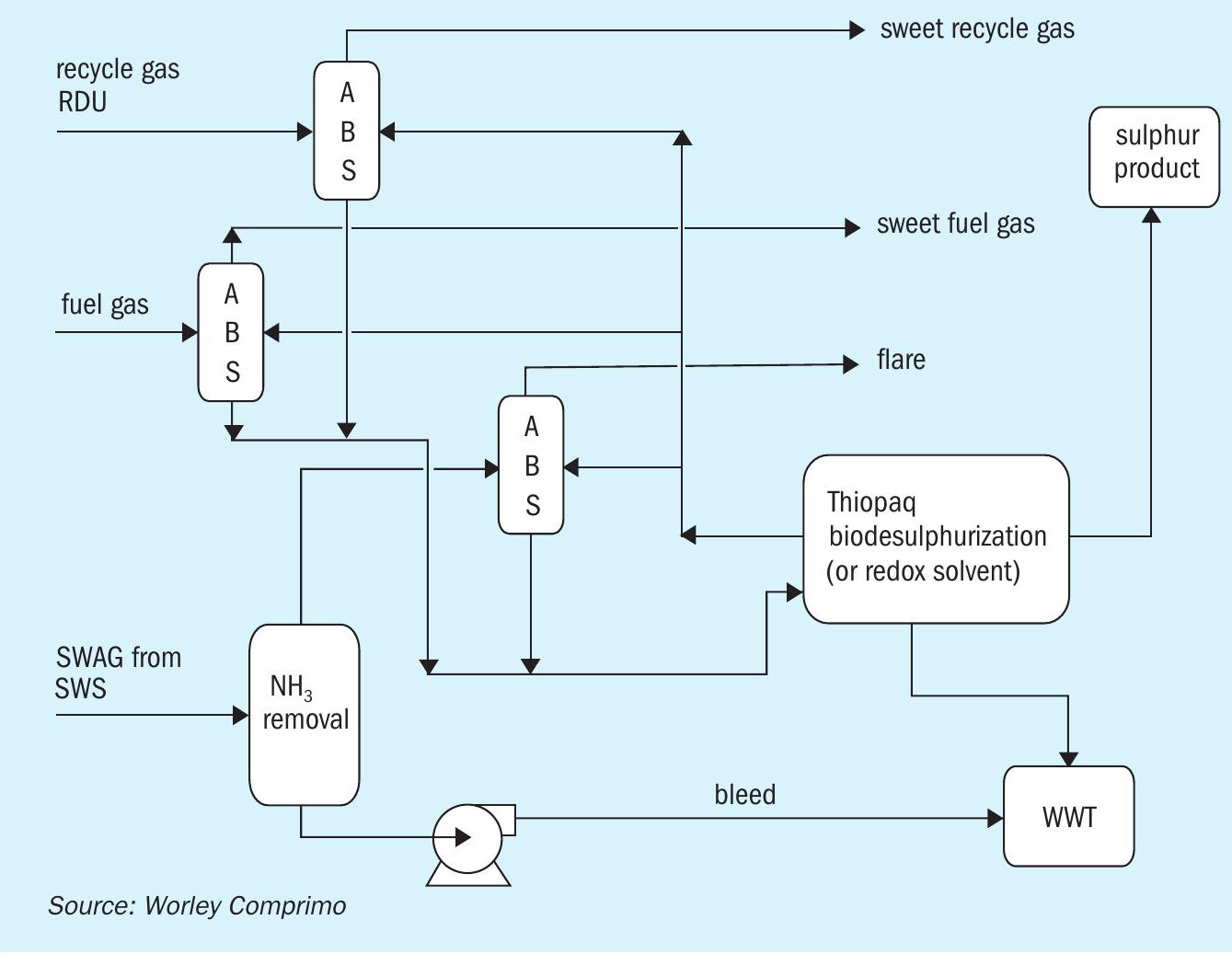
If the biofuel plant is truly grassroots, consideration should be given to get away from traditional amine systems for recycle gas and fuel gas scrubbing. One way is to integrate sweetening absorbers directly into scavenging technology so that sour water acid gas is made ammonia free (Fig. 11).
The primary benefit of this particular line-up is that only a sour water stripper remains of the traditional line-up of a sulphur complex in a refinery. There is no need for an amine system or traditional sulphur recovery unit anymore. Once the ammonia is removed from the sour water acid gas, there is only one system that can remove and convert all of the H2 S in the sour gas streams, thereby eliminating the requirements for costly incinerators and scrubbers. Proper evaluation of the disposal of the waste products will still be required, however the system could be simplified substantially.
Due to the availability of an existing infrastructure in a conversion project, this scenario may not be the most likely candidate for selection. However, for grassroots facilities where there is no existing amine or sulphur recovery unit, this line-up could prove to be most economical both in capex and opex.
Conclusions and recommendations
Refineries seeking to produce renewable diesel through co-processing, conversion, or grassroots facilities need to holistically examine the impacts on their sulphur block. Co-processing essentially increases the CO2 slightly while grassroots or conversions result in gas compositions that cannot be handled on its own with an SRU such that other sulphur removal technologies may need to be used.
Processing bio-feed in conversion/ grassroots renewable fuel refineries results in:
- needing additional capacity at the sour water stripper and acid gas treatment plants;
- existing sulphur block units from existing refinery infrastructure will likely be substantially oversized;
- acid gas feeds will be too low in H2 S with lots of CO2 , requiring CO2 removal (AGR) and/or H2 S enrichment (AGE) before being processed in the SRU.
- ultra-low sulphur tonnage capacities that are better suited to scavenging or scrubbing technologies;
- increased sour water flow rates with NH3 , H2 S, and CO2 may lead to debottlenecking requirements of the existing sour water strippers;
- issues with destroying the increased ammonia in conversion projects.
Ammonia is a crucial component to be considered in decisions regarding processing renewable fuel feedstocks. Some additional oxygen or split flow to the second zone of the thermal reactor may need to be considered. In the case of a full conversion or grassroots biofuel facility, the ammonia can pose a substantial issue as in most scenarios there is no feasible way to either reuse an existing SRU or install a new SRU that can handle the low concentrations of H2 S in the total acid gas. Therefore, alternative methods need to be found in the line-up that ensure that the ammonia does not become a source of emissions. Options discussed include high turndown SRU operation with co-firing, ammonia scrubbing as part of the technology solution and ammonia incineration with caustic scrubbing to remove SO2 . Each potential option needs to be evaluated from an opex and capex perspective as well as how it impacts the facility environmentally.
Most notably, conversion projects should be holistically looking into repurposing/integrating the sulphur block with the new facilities to meet feasibility and environmental compliance. The decision to retrofit the existing sulphur recovery units highly depends on the sizes of the existing units as well as the ability to maintain satisfactory operation with the poorer quality acid gas streams. As shown, many other technologies are available to effectively handle the changed sour gas, amine acid gas, and sour water streams.
Finally, if the renewable fuel plant is truly grassroots, technology selection should move away from traditional amine systems and opt for recycle gas and fuel gas scrubbing. Ultimately, projects must be evaluated on a case-by-case basis resulting in multiple options, for which the client will have preferences for the final design (and never-ending queries to study more technologies).
References
Acknowledgement
This article is based on papers presented at the Sulphur + Sulphuric Acid Conference 2022 and SulGas 2023 conference.
Sulphur 406 | May -June 2023 www.sulphurmagazine.com