Nitrogen+Syngas 384 Jul-Aug 2023
31 July 2023
A new adsorptive CO2 removal process
BLUE AMMONIA
A new adsorptive CO2 removal process
Linde has developed a new adsorptive carbon dioxide removal process, called HISORP® CC, including but not limited to blue ammonia production. Based on a combination of mature technologies the process overcomes the drawbacks of traditional CO2 removal techniques and provides a carbon capture rate of greater than 99%. Thomas Ried discusses the pros and cons of different process configurations for CO2 removal and the benefits of the new technology.
To slow down or even limit global warming requires a significant reduction in greenhouse gas emissions within the next decades. Global ammonia production contributes to approx. 2% of the total carbon dioxide emissions worldwide, so this industry has a significant potential to reduce global greenhouse gas emissions. The highest carbon dioxide reduction is achieved by producing green ammonia with 100% renewable power.
However, green ammonia still faces challenges, e.g., cost and availability of green power. An alternative solution for the short and medium term, transitional phase is blue ammonia, which is still produced from fossil feedstock, but with significantly reduced carbon dioxide emissions. These emissions are avoided by capturing and sequestration or utilisation of the generated carbon dioxide.
CO2 removal processes
Carbon dioxide can be removed by applying absorption, adsorption, condensation, or membrane processes. Each of the different carbon dioxide removal techniques has its advantages and disadvantages.
Absorption: The most popular absorption processes are amine-based washing or Rectisol units. Absorption processes can remove carbon dioxide selectively, which results in a high carbon dioxide concentration. One of the major drawbacks of these processes is the thermal energy requirement for regeneration of the washing agent. In large industrial plants, steam is usually used for the regeneration. Steam is typically produced by firing fossil fuels, which will cause additional carbon dioxide emissions. Moreover, the purified gas and also the carbon dioxide is either saturated with water or methanol and carbon dioxide is recovered at low pressure. Consequently, carbon dioxide needs to be dried and compressed or liquefied for transportation.
Adsorption: Carbon dioxide removal by adsorption can be done by pressure swing adsorption (PSA) or temperature swing adsorption (TSA). For bulk removal and in particular if the feed is provided at higher pressure (larger than 7 bar), PSA units are superior. The big advantage of adsorption processes is that no consumption, handling, and disposal of chemicals is required. Additionally for PSA units, no thermal energy is needed, adsorption units are very flexible and simple to operate. Moreover, they can easily be skid-mounted and prefabricated. This minimises construction costs and reduces the uncertainties of a stick-built unit at the construction side. The major drawback is the lower achievable carbon dioxide purity. As the adsorption is less selective than absorption, the carbon dioxide will always be contaminated with other components like hydrogen, water, carbon monoxide, nitrogen, or methane. Similar to the absorption processes, the carbon dioxide is recovered at low pressure.
Condensation: As carbon dioxide removal by condensation is operated at temperatures below 0°C, the gas needs to be dried upstream. Otherwise freezing of water and hence blocking of valves, piping and heat exchanger passages may occur.
Additionally, cooling and condensing the gas requires significant refrigeration capacity, which requires large machines. Advantageous is the high achievable carbon dioxide purity.
Membrane: A membrane separates components with a thin, semipermeable barrier on the basis of different permeate velocities. Some components, e.g., hydrogen, pass through the membrane quickly, while others, like hydrocarbons, require more time. Membranes are cost-efficient units, which need no regeneration; however, additional machinery might be required as they demand a certain pressure ratio of feed to permeate. Similar to a PSA, the carbon dioxide cannot be recovered with high purity.
To overcome the drawbacks of these processes, different carbon dioxide removal/purification techniques have to be combined to produce carbon dioxide with the requested purity.
HISORP® CC
Linde has developed an adsorptive carbon dioxide removal process, called HISORP® CC. It is a highly flexible, hybrid solution combining mature, proven Linde inhouse technologies, consisting of pressure swing adsorption (PSA) for carbon dioxide enrichment, gas dehydration, for example by temperature swing adsorption (TSA), gas compression by multistage turbo compressors and a cryogenic purification unit.
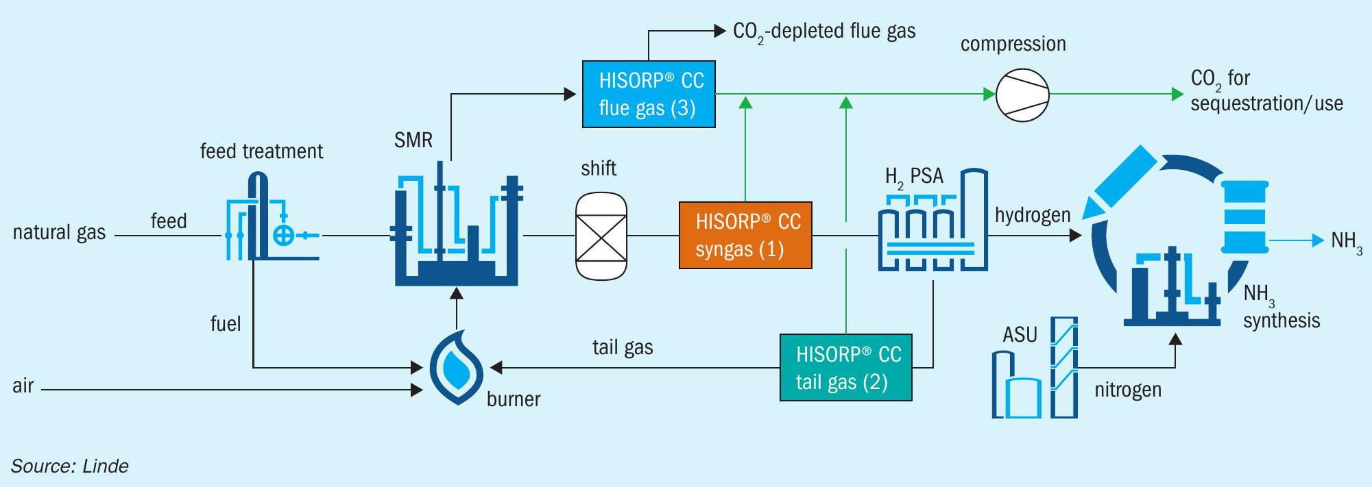
Following the Linde Ammonia Concept (LAC™ ), ammonia is produced from pure hydrogen and nitrogen. To decarbonise the hydrogen production, the carbon dioxide removal can either be placed in the syngas, after the carbon monoxide shift converter, in the hydrogen PSA tail gas, or in the flue gas.
If HISORP® CC is placed in the syngas, the lowest specific energy demand per tonne of removed carbon dioxide can be achieved. The highest carbon capture rates (>99%) can be realised by carbon dioxide removal from the hydrogen PSA tail gas or from the flue gas and provide the optimum solutions to retrofit existing plants.
FUNDAMENTALS OF ADSORPTION
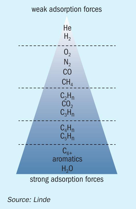
Adsorption is the attachment of a molecule from the gas or liquid phase to a solid surface (the adsorbent). During adsorption, energy will be released in form of heat. The energy is called adsorption enthalpy and serves as an indication for the adsorption forces. Fig. 1 shows a ranking of adsorption forces for different components for technically applied adsorbents. It illustrates that adsorption can be applied for the purification of hydrogen since hydrogen is hardly adsorbed.
Moreover, it shows that carbon dioxide has medium adsorption forces and so it can easily be separated from hydrogen, oxygen, nitrogen, carbon monoxide and methane. Water has even higher adsorption forces than carbon dioxide, that is why carbon dioxide and water can only be separated together from hydrogen, nitrogen, etc. in one stage.
As adsorption is a batch process, at least two adsorbers are required to establish a quasi-continuous process. One adsorber is in the adsorption mode, while the other adsorber is in the regeneration mode. The method of regeneration provides the most popular basis to classify adsorption processes. Pressure swing and temperature swing adsorption units are widely applied.
Depending on the product requirements, the carbon dioxide can be delivered in liquid state or be compressed above supercritical pressure. Decarbonisation of the nitrogen generation as well as the ammonia synthesis can be performed by switching from conventional power supply to renewable power.
LAC with SMR and HISORP® CC
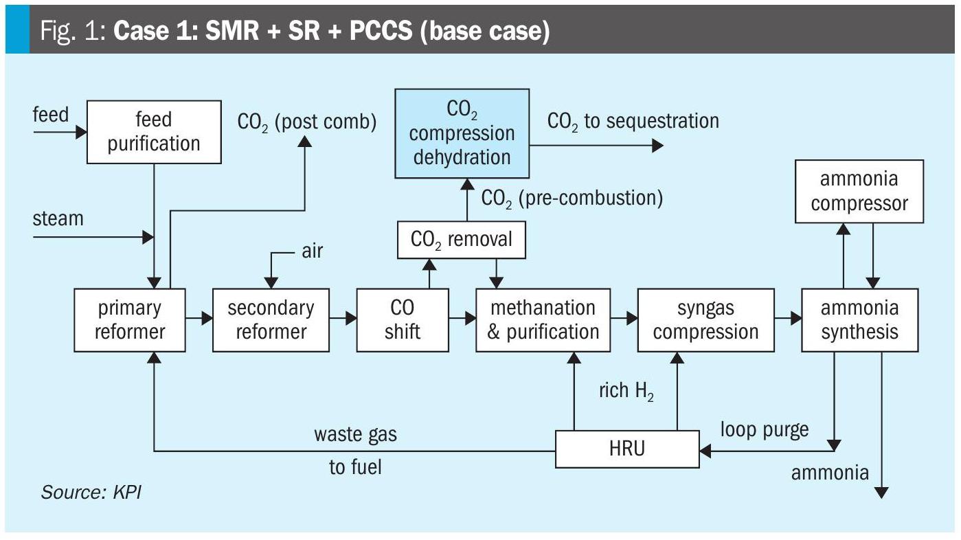
In a conventional hydrogen production plant based on steam methane reforming (SMR), there are several potential locations for carbon dioxide removal.
Fig. 2 indicates three different locations for carbon dioxide removal.
Option 1: Carbon dioxide can be removed from the syngas downstream of the carbon monoxide shift converter. To enhance hydrogen production, the equilibrium of the water-gas shift reaction should be shifted towards hydrogen as much as possible. Therefore, a two-stage shift with high and low temperature, or an isothermal shift is proposed. Depending on the feedstock and the process conditions, the carbon dioxide content at this location varies between approx. 15 and 25 mol-%. Even if the total carbon dioxide amount is removed from the shifted syngas, the carbon footprint of the total hydrogen production can only be reduced by 60-75%. The rest of the carbon dioxide is still emitted via the flue gas from the burners. The carbon dioxide content in the flue gas can be further reduced by using carbon free fuels, e.g., hydrogen. As the syngas is at elevated pressure, the specific energy demand per tonne of removed carbon dioxide is lowest of all three options. The HISORP® CC unit will be designed with minimal pressure drop, e.g., 500 mbar and without hydrogen loss.
Option 2: In the second option, HISORP® CC is applied in the hydrogen PSA tail gas. The carbon dioxide content in the tail gas varies between 38 to 60 mol- %. The large range is due to the influence of the feedstock, the process conditions, and the PSA recovery rate. The carbon capture rate is similar to option 1. However, the overall carbon capture rate can be increased far above 90%, even as high as 99%, if the carbon dioxide depleted tail gas is recycled to the reformer as feed and if the fossil fuel of the burner is substituted by e.g., hydrogen or carbon dioxide depleted syngas. As a result, the flue gas is almost free of carbon dioxide. The total recycle is possible as methane and carbon monoxide are converted to hydrogen and no removal for trace impurities like nitrogen is required. The nitrogen can leave the hydrogen production via the purified hydrogen. The recycle will increase the size of the syngas production plant.
Option 2 has a slightly higher specific energy demand to remove the carbon dioxide compared to option 1. However, much higher carbon capture rates can be achieved with the tail gas recycle. Alternatively, the carbon dioxide depleted tail gas can be routed to a second hydrogen PSA to recover additional hydrogen. As a result, either the feed consumption can be reduced, or the overall hydrogen production can be increased. If the ammonia loop and also the ASU have some spare capacity, even the ammonia production can be enhanced. Option 2 represents a good solution for the retrofit of existing hydrogen plants as only minor changes like adjusting the burners for carbon dioxide depleted tail gas, are required. The specific energy demand of the second option is slightly higher than for the first option, as the hydrogen PSA tail gas has low pressure and thus compression is required.
Option 3: The third option is the removal of carbon dioxide form the flue gas which has a carbon dioxide content of 15 to 22 mol-%.
As the flue gas is emitted at atmospheric pressure, gas compression is required. Due to large flue gas streams and the low pressure, the compression is very energy intensive. As a consequence, this option requires the highest specific energy demand per tonne of removed carbon dioxide. To optimise the opex, the pressurised and carbon dioxide depleted flue gas can be sent to an expansion turbine. With the additional machinery at least a portion of the electrical energy can be regained. The carbon dioxide enrichment within the HISORP® CC process can be done either by pressure swing or by vacuum swing adsorption. The vacuum enhances the desorption and thus increases the recovery rate and the capacity of the PSA.
The big advantage of post carbon capture is the high carbon capture rate >99% and that no modification of an existing plant is required. Thus, making it the optimum retrofit solution. As almost all carbon atoms from the feed and fuel end up in the flue gas as carbon dioxide, the achievable carbon capture rate is maximum for this option. Unlike absorption processes, HISORP® CC has no sensitivity to oxygen, which is a strong benefit for the flue gas application compared to alternative processes. HISORP® CC can also be implemented in other industries to recover carbon dioxide from the flue gas, e.g., from cement, lime, or steel plants.
With all three options the carbon dioxide at the outlet of HISORP® CC is dry and at a pressure of approx. 7 bar(a), unlike absorptions processes, which is sent a real benefit when the carbon dioxide has to be compressed to supercritical pressure for transportation and sequestration. For the compression an integrally geared turbo compressor can be applied. As the carbon dioxide is dry, no knock-out drums after the interstage coolers are required. Moreover, the material selection for this compressor is less challenging than for the compression of wet carbon dioxide.
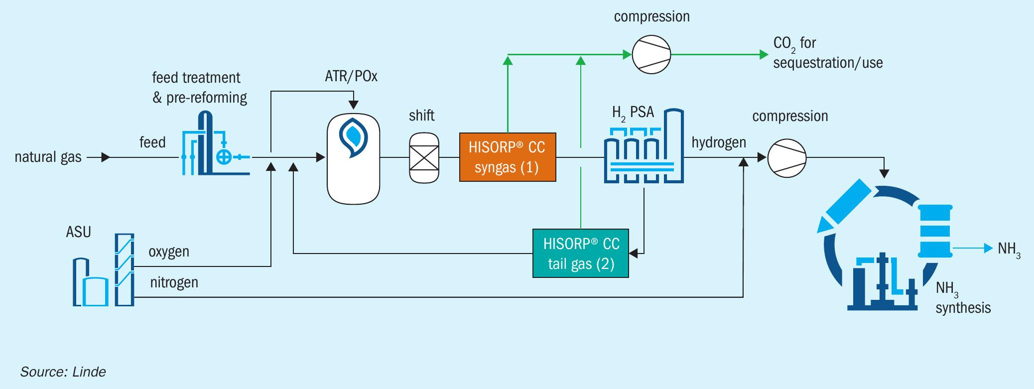
LAC with ATR or POx and HISORP® CC
HISORP® CC can also be applied in the LAC™ , where the hydrogen is produced by ATR or POx as an alternative to SMR. Oxygen will be required and can be provided by the ASU.
Fig. 3 shows an overview of options where HISORP® CC can be applied in the LAC™ for these cases. The flue gas option is not shown here, as for the ATR or the POx concept only a minor amount of flue gas is generated in a fired heater, which is not shown in Fig. 3 for simplification. This additional fired heater is required, for example, for feed heating, for steam production or steam superheating. In principle, HISORP® CC can be applied in the flue gas of the fired heater, if fossil fuel is applied. Options 1 and 2 are similar to the SMR alternative. Compared to the SMR options, the specific energy demand is slightly lower, as the carbon dioxide content is typically higher due to the reduced methane slip of the ATR or POx.
For option 2, HISORP® CC in the hydrogen PSA tail gas, a total recycle of the tail gas is not possible. Otherwise, argon will accumulate within the loop. Argon enters the system via the oxygen and cannot leave the hydrogen production via the purified hydrogen as argon is disadvantageous in the ammonia synthesis loop.
Figs 2 and 3 show the production of ammonia from natural gas, but the procedure can also be applied to other feedstocks like naphtha, coal, or biomass.