Nitrogen+Syngas 388 Mar-Apr 2024
31 March 2024
In-service monitoring of HE tube wall thickness
DIGITAL SOLUTIONS
In-service monitoring of HE tube wall thickness
Aleksandra Gavrilović-Wohlmuther of Christof Group SBN presents groundbreaking sensor technology for accurate and reliable continuous monitoring of individual heat exchanger tube wall thickness in high pressure, high temperature industrial conditions.
Plants in the chemical, oil and gas, nuclear, and power generation industries, all rely to a large extent on metal structures comprising extensive metal tubes or pipework. Consequently, they all share one common issue, that is the detriment of a metal structure. Over long periods of service, corrosion and erosion of metal is inevitable, thus regular monitoring for the assessment of the structural integrity of the material and accordingly maintenance is of utmost importance to extend the lifetime and optimise the time between maintenance. The onset and propagation of corrosion is even faster in conditions of elevated temperature and pressure. Such deterioration leads to accelerated wall thickness loss, which is a threat to structural integrity and load resisting capacity of the pipes and tubes. Consequently, over time these metal components need to be repaired, replaced, or removed. Practice has shown however, that the wall thickness loss can be tolerated to some extent.
Without adequate in-operando monitoring, plant operators have littleto-no warning of developing problems. In this business, efficiency and safety are paramount. The standard approach is to schedule process unit or plant for a non-operational state, known as “shutdown”. The maintenance and inspection of the heat exchanger (HE) tubes have traditionally been a time-consuming and costly process since each component shall be examined individually. The manual inspections have a limited reliability, considering the accuracy depending on the operator’s skill or condition, measuring instrument and possible difference in data reading conditions. Moreover, the financial impact of the scheduled downtime on revenue is critical. Maximising the time between the shutdowns can yield substantial gains for the plant’s profitability.
This article introduces a ground-breaking solution developed by Christof Group SBN, which promises to revolutionise this aspect of industrial maintenance by offering an original product that smoothly combines cutting-edge sensor technology with a real-time monitoring capability. This innovation allows for the early detection of wall thickness changes induced by corrosion and/or erosion within the heat exchanger tubes. Importantly, the new technology operates continuously, delivering in-situ monitoring, even under high-pressure and high-temperature (HPHT) conditions. Two distinct sensing systems have been harnessed for this purpose, one based on ultrasound and the other based on fibre optic interferometry. Both sensor technologies enable detection of real-time changes in wall thickness, with proven accuracy up to 0.05 mm at 220°C and 20 MPa for HE tubes made of any super-duplex steel. This innovation is however intended for any metallic HE tubes operating under HPHT.
Christof Group SBN’s sensors play a crucial role in advancing the digitalisation of industrial equipment. Their recent integration into a high-pressure CO2 stripper is a testament to their practicality and potential to enhance the efficiency of fertilizer plants while reducing the financial burden associated with scheduled maintenance shutdowns. This article delves into the technical aspects of two patented sensor systems and underscores its commercial significance in supporting customers seeking streamlined operations.
WALLMON® – fibre optic sensing system
Optical fibres, primarily made of quartz glass, have a melting point of around 1,700°C, with high compressive strength > 1 x 10⁹ Pa and an extraordinary chemical inertness. Due to these outstanding thermal and mechanical properties, fibre-optic sensors are resistant to the corrosive ambient and harsh industrial environments such as those encountered in critical process equipment in the fertilizer industry. A special feature of the fibre optic sensor is that it requires no electrical wiring to connect to the control system, as optical fibres themselves act as both, the sensing element (so called intrinsic sensor) and the signal propagation channel. The WALLMON® fibre-optic sensing system guaranties absolute safe in-service operation without any risk induced by sparking, short circuit, EMI, RF and HV interference, as the sensing element does not contain any electrical currents. Being made of dielectric materials, it is intrinsically an Ex-proof sensing technology.
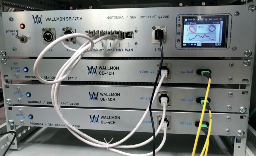
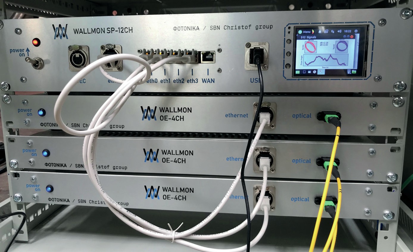
Beside the network of optical fibres placed at the measurement points, the WALLMON® sensing system includes an optoelectronic unit (OEU), as shown in Fig. 1, responsible for interrogation of fibre-optic sensors and online signal processing. The full supervision of the heat exchanger tubes is based on the remote and safe data transmission and communication between the embedded sensors and OEU over a long distance.
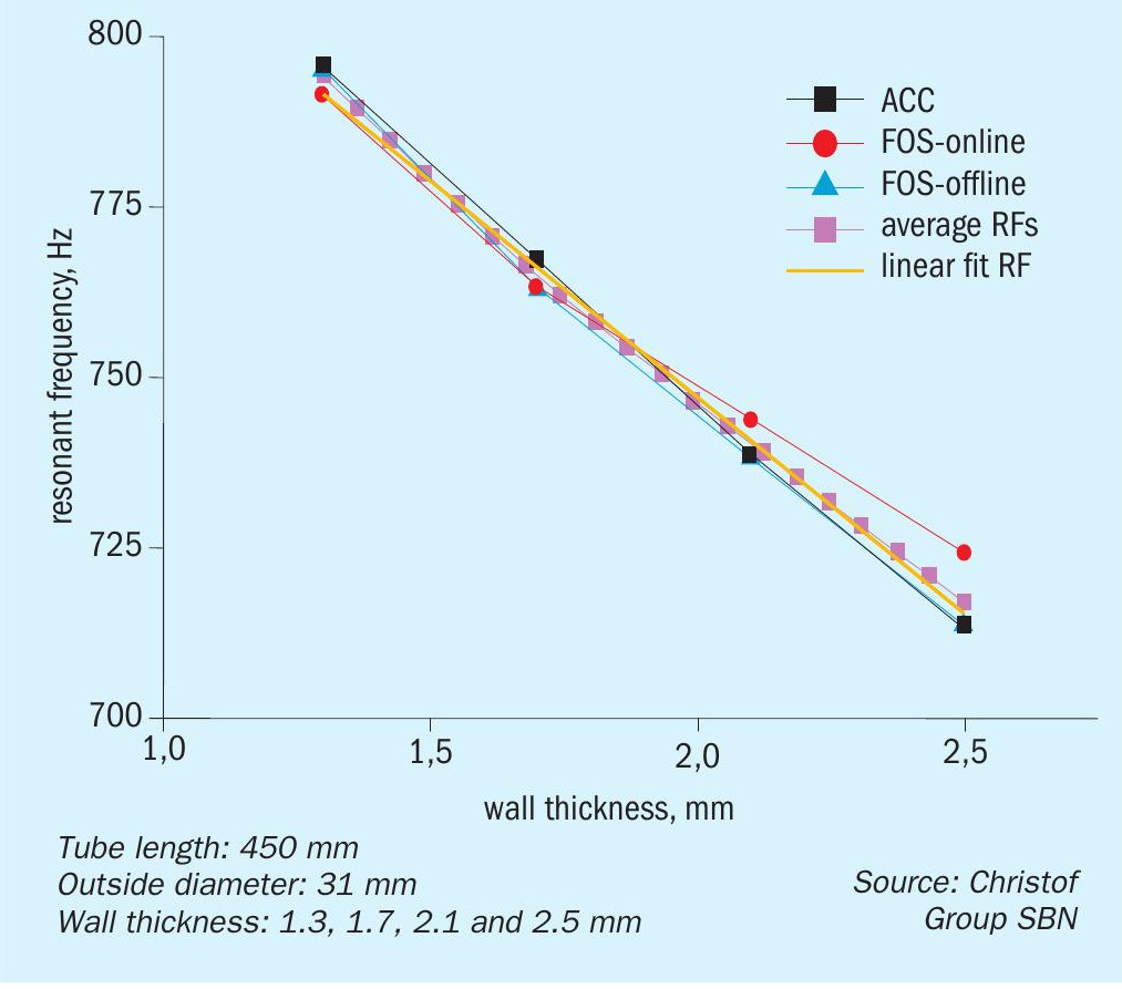
During operation, vibration of the critical process equipment, thus heat exchanger tubes is an inevitable occurrence. The WALLMON® sensing system uses this unwelcome effect as an acoustic driver to monitor the frequency response and to estimate the wall thickness of the inspected tube. A wall-thinning of the heat exchanger tube is a result of a permanent loss of the material, that leads towards change of resonant frequency of the tube, shifting it towards higher values (see Fig. 2).
At the same time, the stiffness of the tube wall decreases, causing the change of strain over the tube wall. The sensing fibre is wrapped around the monitored HE tube capturing the quick varying strain signals (0 – 1,000 Hz). The optical signals are converted to the electrical one by means of an OEU. Resonant frequency is calculated out of the FFT analysis of strain signals by online processing in the OEU. To neutralise the thermal effects on the optical path length, each sensing fibre is coupled with one reference fibre.
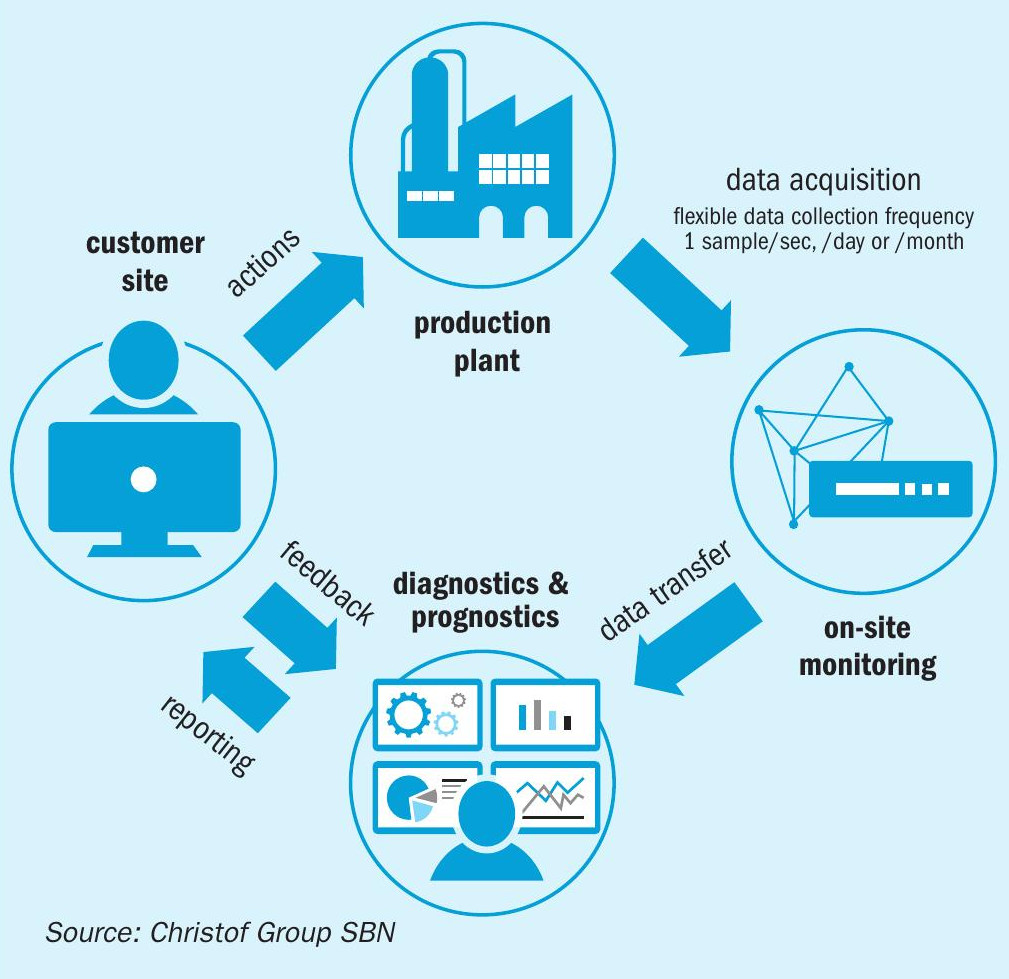
The WALLMON® remote monitoring and diagnostics service (RM&D) enables real-time data acquisition and comparison, whether conducted directly on-site, or accessed remotely through an intranet or internet connection (see Fig. 3).
MONITUBE® – ultrasonic sensing system
The time-of-flight (TOF) method in ultrasonic testing is a technique that revolves around measuring the time it takes for an ultrasonic pulse to travel through a material and return as a reflected signal. This approach is increasingly popular because it enables the measurement of wall thickness in industrial settings, specifically on parts that are only accessible from one side. Additionally, it is a quick, straightforward, and versatile technique that lends itself well to automation.
The MONITUBE® ultrasonic sensing system developed by Christof Group SBN is based on the TOF method using high temperature piezoelectric ceramics, which generate a corresponding output signal by means of high-frequency excitation. Due to the high speed, many measurements can be carried out, which, by averaging the individual values, greatly increase the measurement accuracy. In the face of harsh environmental conditions, MONITUBE® rises to the challenge, delivering impeccable measurement signals. A common issue that this sensing system has mastered successfully is the measurement accuracy over time, where no drift in the measurement signal is allowed, even over decades. In the course of development, this ruled out many commercially available sensor components that would begin to drift over time at high temperatures. Another distinctive feature of the MONITUBE® sensor system is that it does not require any coupling medium for the effective introduction of the emitted ultrasound signal into the test area. The sensing unit is carefully designed so that contact transfer losses can be reduced to a minimum.
In addition to the MONITUBE® sensing unit, which directly interacts with the HE tube, the complete ultrasound sensing setup comprises two additional elements that are placed outside the high pressure heat exchanger; an electronic hub functioning as the core of the measurement system and a user terminal for accessing measured values and adjusting settings. Employing the cutting-edge digital circuitry, the electronic hub can simultaneously assess between 8 and 16 MONITUBE® sensors. This hub is connected to the user terminal via Modbus.
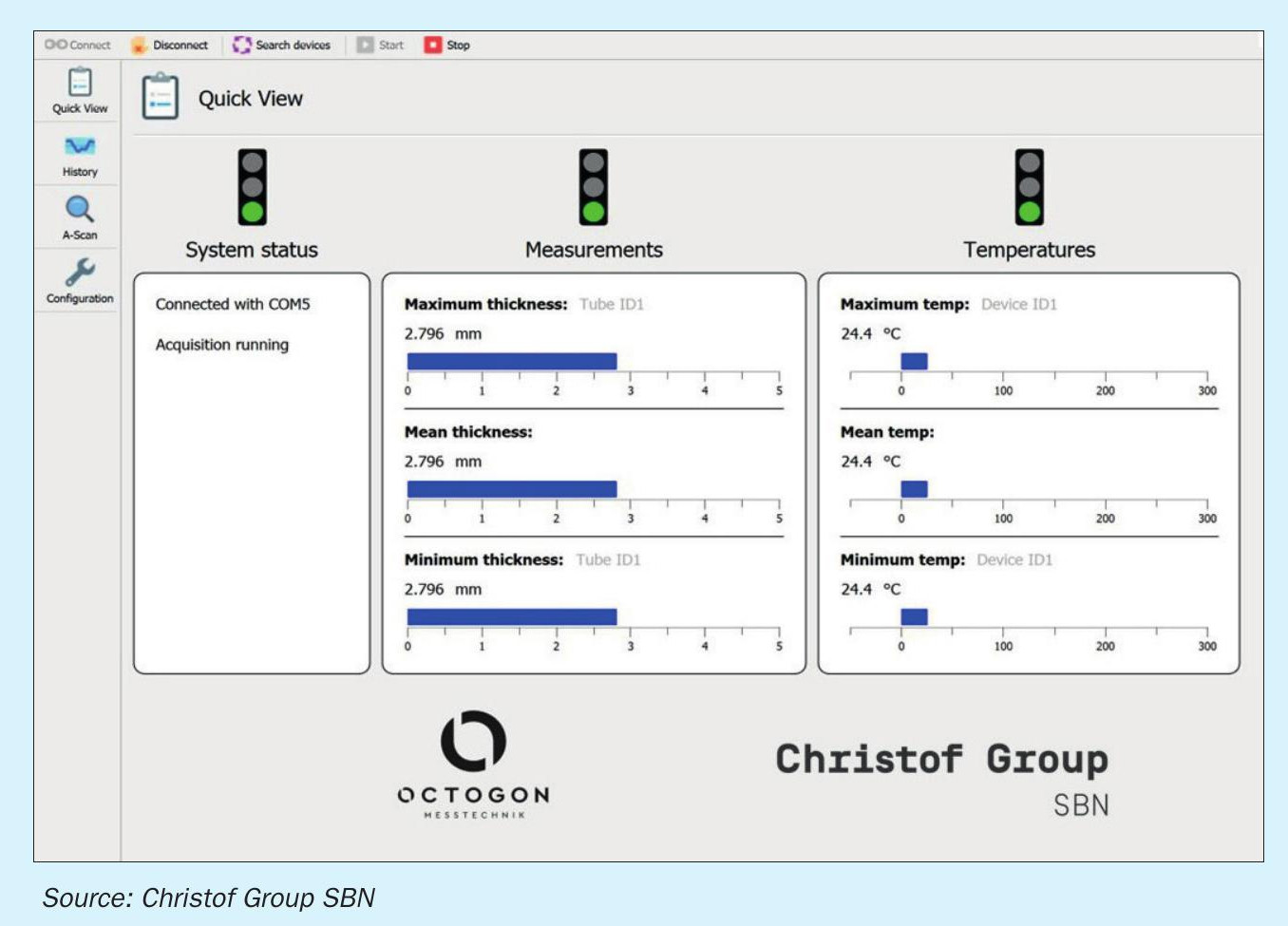
For assessing measured data, an intuitive graphical user interface (GUI) is available. By using a traffic light sign, the “Quick View” interface symbolically displays the overall status, wall thickness and current ambient temperature (see Fig. 4). Additionally, the “History” interface not only allows real-time inspection of actual status but also enables users to retrieve past measurements for graphical comparisons, providing a means to evaluate visually wall thickness development over the time. The frequency of the measurements can be adjusted remotely.
Sensor placement and installation
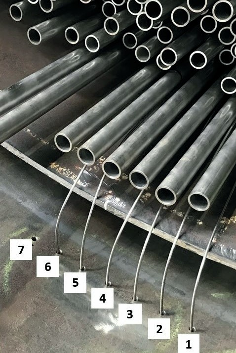
In addition to creativity, a deep understanding of material behaviour and excessive know-how in engineering and manufacturing of critical process equipment are essential for successful sensor design, placement, and installation in an actual heat exchanger. A specific area identified as the most prone to corrosion is the most beneficial for the sensor placement. The combination of high demands on pressure resistance, heat resistance, occurring steam atmosphere, as well as the challenge of lead out of the measuring signals makes these sensing systems unique. Finally, the overall concept considers very limited installation space since the sensors are placed on and between the HE tubes, without interfering in the process (see Fig. 5). Consequently, Christof Group SBN has refined its typical production procedures, all directed toward achieving the utmost efficiency while ensuring the safe and minimally intrusive installation of sensors.
Future steps
During a month-long laboratory testing in the autoclave, both sensor technologies performed impeccably, enduring extreme conditions of up to 225°C and pressures of up to 20 MPa in water steam. This rigorous testing validated their precision to maintain a remarkable accuracy of 0.05 mm in detection of wall thickness changes, showcasing the components’ resilience and suitability for harsh operational environments.
Recently, one of the sensor technologies was delivered for the first time to a valued customer of Christof Group SBN. Commissioning is set for 2024, signalling the next phase of development. This stage presents an exciting opportunity to put the sensors to the test in a real-plant scenario, uncovering insights into their long-time endurance and paving the way for potential enhancements.
Conclusion
In summary, Christof Group SBN presents ground-breaking sensor technology designed to revolutionise industrial operations. By integrating advanced sensors capable of continuous, real-time monitoring, this innovation detects early wall thickness changes due to corrosion and erosion in heat exchanger tubes. The WALLMON® fibre optic sensing system and MONITUBE® ultrasonic sensing system offer unparalleled accuracy and reliability even in extreme conditions, promising enhanced safety, efficiency, and cost savings for industries reliant on metal structures. The imminent deployment in 2024 heralds a new era in predictive maintenance and operational excellence.