Nitrogen+Syngas 389 May-Jun 2024
31 May 2024
Ammonia combustion for large furnaces
AMMONIA CRACKING AND COMBUSTION
Ammonia combustion for large furnaces
Ammonia has been recognised as an advantageous hydrogen and energy carrier. This article focuses on the use of ammonia as fuel in steam reformers and ammonia crackers in order to reduce or completely eliminate direct CO2 emissions. Ammonia combustion knowledge is especially important for ammonia crackers with respect to the recycling of unconverted ammonia. Air Liquide is constructing an industrial scale pilot plant in Antwerp, planned to be operational in 2024, that will be used to demonstrate ammonia cracking and combustion in a process furnace with a multiple burner configuration.
Ammonia (NH3) is the second largest volume commodity chemical. Global production of ammonia is approximately 185 million t/a (2020) of which 20 million t/a are traded globally thanks to relatively simple transport requirements and more than 200 maritime ammonia terminals.
The global ammonia market is expected to double in size by 2050 with an increasing portion being produced in a non-conventional manner. Produced by either renewable power (e.g. hydrogen produced from the electrolysis of water) or by hydrogen from fossil fuels with carbon capture and storage, ammonia offers two alternative pathways to supply decarbonised hydrogen or energy.
In either case, this non-conventional ammonia will play a key role in connecting regions rich in low carbon or renewable energy to those in demand of it. Ammonia as an energy carrier is thus expected to be a key enabler towards a decarbonised world.
As part of its ADVANCE strategy to further decarbonise its plants, Air Liquide’s ammonia cracking technology development is a critical step to unlock access to additional low carbon and renewable hydrogen derived from imported ammonia. Air Liquide licenses, builds, owns and operates traditional hydrocarbon-based steam methane reformers, autothermal reformers, partial oxidation reactors, and is currently implementing its own carbon capture technologies, i.e. Cryocap™ , Recticap™ and amine wash solutions, both on the process and flue gas side in order to reduce CO2 emissions of its plants. Combustion knowledge is essential for these technologies, especially with increasing use of hydrogen, biogas and ammonia as new fuels.
Air Liquide will start up an industrial scale pilot plant for ammonia cracking and combustion in Antwerp in 2024 to gain valuable combustion knowledge.
Applications of ammonia combustion
As an energy carrier, once shipped to high energy demand countries, ammonia can be used directly as a fuel in existing and new plants according to the following equation:
2NH3 + 1.5 O2 → N2 + 3H2O + 635 kJ
It is already under development for use in power production in gas turbines1 , but also as a co-fuel for coal fired power plants2. Similarly, engine manufacturers consider ammonia as one of the fuel options for maritime decarbonisation. Outside of several notable demonstrations, large-scale use as fuel has never been applied in reformers (e.g. fired heaters, hydrogen production reformers, ethylene crackers) and other energy-intensive industries such as glass, cement and steel.
Ammonia cracking
In hydrogen production units via ammonia cracking, ammonia is split into hydrogen and nitrogen, the hydrogen is separated at high purity and the remaining components, nitrogen, non-separated hydrogen and unconverted ammonia are recycled as an off-gas fuel to the process. This off gas mainly consists of nitrogen and has a rather low calorific value which makes it challenging to combust. Direct use of ammonia vapour as a trim fuel – to close the heat demand for the endothermic cracking reaction – is the ultimate goal.
Indeed, either cracked gas (N2 /H2 mixture) from the process or product are technical solutions with the highest technology readiness level (TRL). However, ammonia combustion is especially beneficial for ammonia crackers with respect to the recycling of unconverted ammonia. The unconverted ammonia can be tolerated in the process and subsequently recycled to the fuel. Furthermore, using product hydrogen as trim fuel is less economical, since all the hydrogen production equipment would be oversized with consequently higher capex.
Depending on the required hydrogen purity at the battery limit and the overall process integration, the required fuel flow to balance the heat demand will change and the fuel mixture of ammonia trim fuel and process off gas will be different in composition and combustion properties.
Steam methane reforming
In SMR plants, direct application of referenced carbon capture units on the process side combined with the use of ammonia as trim fuel for the firing side are crucial for reaching minimum CO2 emissions. In particular, hydrocarbon fuel substitution by ammonia in reformers for the production of carbon monoxide can significantly reduce the carbon footprint of the product. Moreover, since cold ammonia will be available at the plant, further heat integration and energy reductions are possible, depending on customer needs.
Challenges in ammonia combustion
Ammonia is an interesting carbon-free fuel, but its implementation in industrial systems raises technical challenges.
Firstly, the low flammability of this reactive species reflects on the fundamental properties of combustion when it is used as a fuel or co-fuel. 1D unstretched premixed flame simulations were launched to quantify the impact of the ammonia contribution to the total fuel power, NH3 duty, on the laminar flame speed, which quantifies the speed of consumption of the fresh gas by the flame front. The higher it is, the stronger the flame anchoring is. Various co-fuel compositions were considered: BF1 and BF2 correspond to classical SMR fuel compositions (containing a mixture of CH4, CO2 and H2 ), and GF1 and GF2 correspond to pure hydrogen and hydrogen/nitrogen fuel mixtures. The results are plotted in Fig. 1. Ammonia co-fuelling clearly results in decreased laminar flame speed levels, whatever the co-fuel composition.

Extinction strain rate in 1D counterflow flames is another important fundamental combustion property. It quantifies the flame resistance to turbulent straining. The higher it is, the stronger the flame is. Here again, it can be readily seen that ammonia tends to weaken the flame. From an industrial perspective, lower flame speed and extinction strain rate translate into technical challenges in flame stabilisation requiring know-how development and burner technologies to be adapted.
Finally, the main concern about ammonia combustion is related to the higher formation of NOx compared to a standard SMR. Global NOx emission regulations are becoming increasingly stringent, especially in those countries where ammonia cracking will be operated. Dedicated flue gas NOx abatement systems, such as selective catalytic reduction (SCR), are needed in order to remain below statutory limits. For existing units, the switch to ammonia as trim fuel could challenge the available plot space of the deNOx unit.
In order to design new and retrofit existing furnaces for ammonia fuel, Air Liquide invested in ammonia combustion capabilities at its in-house facilities and performed hundreds of test points at different conditions, coupled with improved combustion models, leading to optimised combustion conditions. Air Liquide has covered the whole range of furnace operation requirements, from start-up to normal operation, in order to guarantee safe and reliable operation. This includes using an efficient combustion and small deNOx system to satisfy all emissions limits in terms of NOx, particularly N2O, and also NH3 slip to the atmosphere.
Experimental test bench
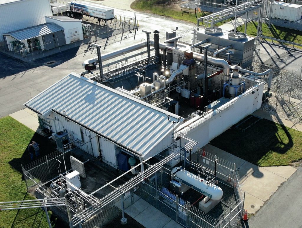
Air Liquide recently upgraded its combustion test platform at Innovation Campus Delaware (ICD) to enable ammonia firing (Fig. 2). The test facility is capable of firing rates up to 6 MW for oxyfuel combustion and up to 2.5 MW for air firing. The enclosure itself (Fig. 3) is 8 feet (2.4 m) in diameter and 22 feet (6.7 m) in length. At the front face of the enclosure, a large opening is provided for mounting different test burners. Several viewports, probe access ports, camera ports and thermocouple ports are available to enable required measurements.


To simulate burner tests with different fuel blends, natural gas, hydrogen, carbon dioxide and nitrogen are available at the combustion test platform. H2, CO2 and N2 are supplied from bulk tanks at the facility. For the supply of ammonia, a bulk tank (Fig. 4) of 1,000 gallon (1,980 kg) capacity was recently installed by Airgas, an Air Liquide company in the United States.

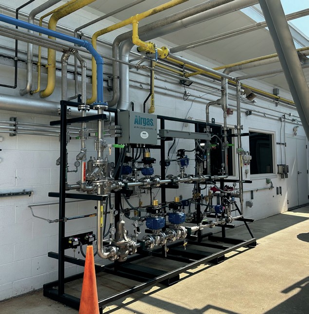
To enable vaporisation of anhydrous ammonia, the tank system consists of a vaporiser (175 kW capacity) allowing continuous gaseous ammonia flow up to 2 MW firing rate. Several ammonia sensors, which are tied to the control system, are installed around the tank, inside the control room and on the combustion platform to ensure the system will shut down safely if ammonia leakage is detected.
Flow control skids complying with the NFPA standard for ammonia and hydrogen were added to enable safe firing of the fuel blends (Fig. 4). The test facility also has NFPA-compliant natural gas and oxygen flow control systems. Ammonia and hydrogen flow control skids have high and low flow branches to enable accurate control at both low and high flow rates.
Either air or oxygen can be used for combustion tests depending on the test requirement. Air can be preheated up to 450°C, to enable testing at realistic process conditions.
Parameters that can be measured are:
- flow rates, temperature and pressure of all the gases used for the test;
- burner back pressure vs. firing rates; l furnace wall temperature profile, obtained via crown thermocouples;
- heat flux profile obtained via the water cooling system;
- flame imaging and IR images for flame dimensions;
- furnace exit gas concentrations (NO, N2O, NO2, NH3, CO, CO2, O2) via continuous emission monitoring analysers, NH3 analyser and FTIR;
- fast acting pressure transmitter to evaluate flame stability;
- burner block temperature.
Tests have been carried out with various full scale, commercial burners (fuel-staged, air-staged and new technologies for ammonia firing) between 1 to 2 MW burner duty with the aim of determining flame stability, emissions and heat transfer characteristics for the whole operating envelope to be used in plants.
Experimental test results
Ammonia combustion tests have been performed in Air Liquide’s new ammonia combustion platform and several theoretical assumptions were validated but also unexpected results were obtained. The detailed test results and analytical data can be used for the design of steam reformer revamps and ammonia cracking plants.
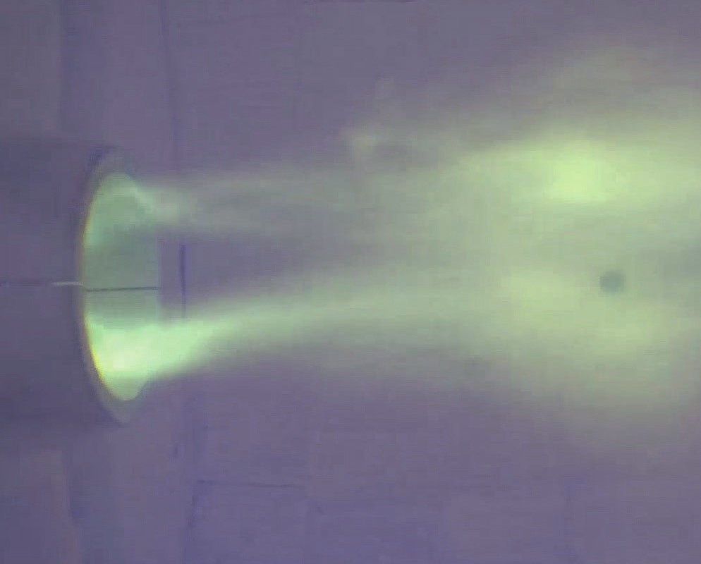
Ammonia combustion has been proven in the experimental campaign both for fuel-staged and air-staged burners. A wealth of measurement data has been generated and practical knowledge, for example on flame scanner adaptation, has been gathered.

Small amounts of ammonia in the fuel mixture are almost one to one converted into NOx emission and lead to significantly higher NOx in ammonia combustion compared to hydrocarbon combustion. However, the NOx emissions do not scale in proportion to the ammonia content in the fuel. Functional relationships have been established between process-specific burner design, operating parameters and emissions. The NOx level of the optimised combustion solution is such that stringent emission limits can be achieved with a special deNOx system.
Higher NOx emissions during ammonia combustion can be understood according to the fuel-NOx kinetic pathway. The NOx emission level varies with process parameter changes in a different manner than hydrocarbon combustion. For example, the air to fuel ratio has a more pronounced influence, whereas the influence of the combustion air preheat and flame temperature is less important.
The formation of N2O can be avoided by the appropriate selection of combustion parameters for the process-specific burner design and furnace.
Modelling tools
Modelling is a complementary and important approach to shed light on ammonia combustion and support the design of industrial units where it is implemented for energy production purposes.
Ammonia is used as fuel for endothermic reactions, so being able to predict the heat transfer processes is crucial to design reliable and efficient fireboxes. Recognising this strategic challenge, two simulation tools have been developed internally at Air Liquide at the Innovation Campus Paris (ICP): 3-dimensional (3D) computational fluid dynamics (CFD) software and 1-dimensional (1D) software. Previously successfully used to support SMR firebox competitive design, these simulation tools have been adapted to handle ammonia combustion and cracking reactions.
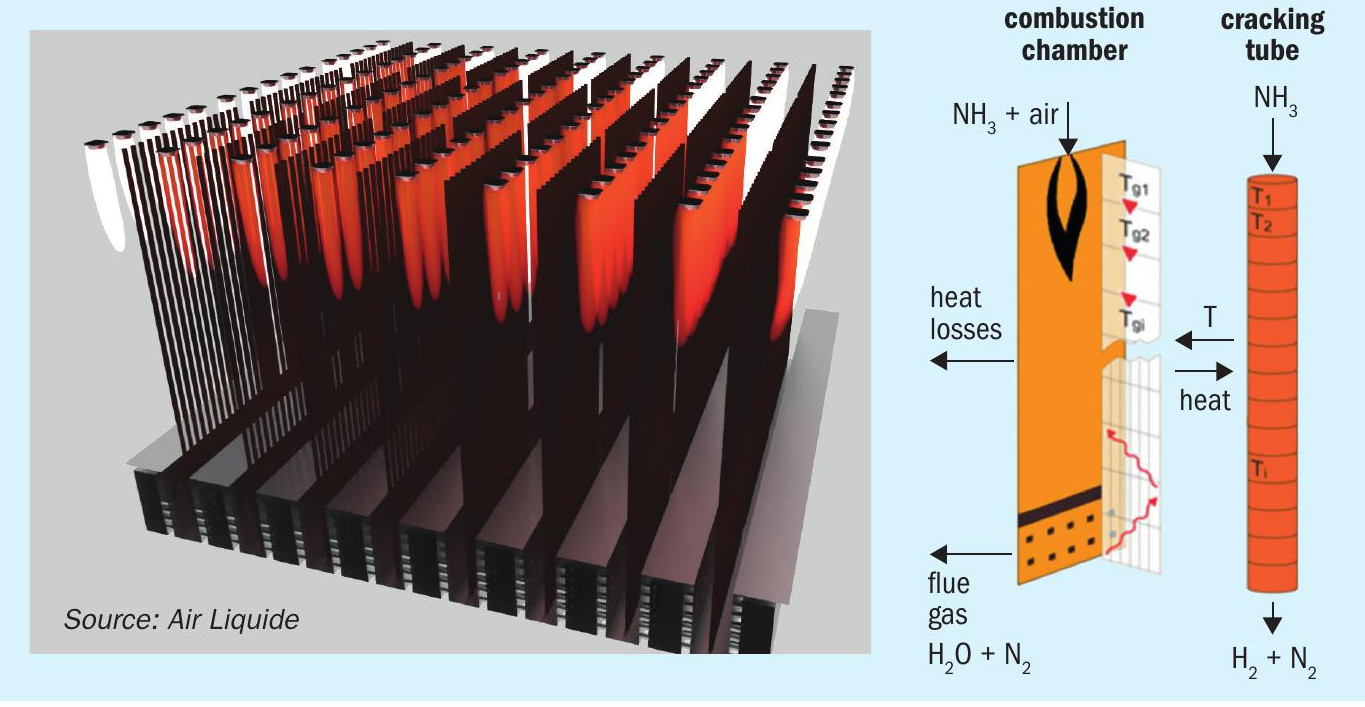
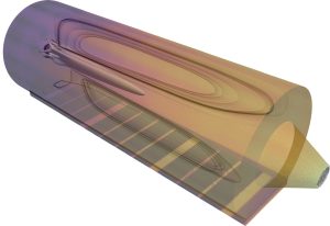
On the one hand, the CFD tool is dedicated to optimising the firebox layout, see left picture in Fig. 6. It includes two coupled physical solvers. Firstly, a 3D CFD solver is in charge of describing the physical processes involved in the combustion chamber. An effective burner model is implemented, making it possible to handle firebox simulations involving hundreds of burners at a reasonable computational time. This model is validated by comparison with advanced CFD simulations of detailed burners, see Fig. 7, also used to gain a deeper understanding of ammonia combustion, as a complement to the experimental tests. Similar to hydrogen combustion, the ratio of the two main radiating species, carbon dioxide and steam, change and thus the radiative properties of the flue gas are different in ammonia combustion compared to hydrocarbon combustion. Radiation and turbulent patterns resulting from the flame interaction are described and their impact on heat flux profiles for each individual tube is reflected. Secondly, the 1D tube model describes the heat transfer process from the tube skin to the catalyst bed as well as the heterogeneous catalytic reactions. Data gathered from catalyst test benches are used for kinetic model validation. This computationally demanding software has been launched on the Air Liquide supercomputer at ICP.
On the other hand, the 1D software tool is designed for fast evaluation of innovative solutions, see right picture in Fig. 6. It includes the same tube model as the CFD tool and a computationally effective combustion chamber model. It can be launched on a laptop and is fully adapted to fast sensitivity analysis and benchmarking.
Radiation is the dominant mode of heat transfer within a firebox and its accurate modelling has required special care in Air Liquide internal software. The physical model accuracy is ensured through a calibration procedure making the most of the valuable data obtained in test benches such as the combustion platform previously described for the industrial scale pilot plant for ammonia cracking and combustion in Antwerp.
Conclusions and next steps
Ammonia combustion is an important technology brick for various applications. Air Liquide’s combustion platform offers the opportunity to perform extensive tests on existing and new burner designs and fuel mixtures (relevant for combustion of NH3, natural gas, H2, N2, off gases or syngas mixtures from biomass gasification). Simulation of such results with sound physical models adds understanding and enables confidence in the design process.
As already announced, the final step in the development of ammonia combustion in large furnaces and especially in ammonia crackers will be realised in an industrial scale furnace with several cracking tubes and burners. The industrial scale pilot plant at Antwerp will not only allow demonstration of the cracking technology, it will also provide the final validation step of ammonia combustion in a process furnace with a multiple burner configuration. The plant is under construction and is planned to be operational in 2024.
The pilot plant at Antwerp and the numerous test results will be exploited to further improve the accuracy of the model predictions for a wide range of operating conditions, in the combustion chamber as well as in the cracking tubes.
References