Nitrogen+Syngas 389 May-Jun 2024
31 May 2024
Ammonia in a future hydrogen economy
AMMONIA CRACKING
Ammonia in a future hydrogen economy
Large-scale ammonia cracking technology and catalysts will enable the full potential of ammonia to be realised as industries transition towards low carbon energy. In this feature we report on the current status of ammonia cracking processes and catalysts.
The world is facing an incredible challenge in the race to decarbonisation, imposing a change of landscape in the technologies and fuels used to support sustainable modern-day life in the future. Coal, oil and natural gas have been transported from the parts of the planet which have an abundance of fossil fuels to those which are short of energy for many decades. As the world decarbonises, the challenge will be to transport wind and solar energy from regions where it is in abundance, mainly in the southern hemisphere, to those which are lacking renewable energy, mainly in the northern region of the world.
Both hydrogen and ammonia are predicted to play a major role in this journey to support the decarbonisation of industries and regions around the world.
Hydrogen is known to be a clean and environmentally sustainable energy vector and is taking a leading position as a sustainable fuel of the future. Ammonia can also be used as a fuel in its own right, but many applications require ammonia to be decomposed back to hydrogen prior to use.
One of the current challenges facing hydrogen technologies is its storage and transport. Although hydrogen has a very high energy density on a mass basis (119.7 MJ/kg of lower heating value at 25°C and 1 bar, while gasoline has 44.79 MJ/kg), it has a very low energy density on a volume basis due to its low molecular weight (8.96 GJ/m3, compared to gasoline with 31.17 GJ/m3 , both referred to as liquid fuels), which leads to storage difficulties.
The most common method of hydrogen storage nowadays is as a compressed gas at pressures of up to 700 bar at room temperature. Alternative solutions are proposed but they all require a large amount of energy which counterbalances the benefits of the hydrogen molecule as a sustainable energy vector.
In addition, the transport of hydrogen as a liquid requires extremely low temperatures (-252°C), leading to high energy consumption for refrigeration and reheating as well as for new technology and infrastructure. The loss of hydrogen due to evaporation during liquefaction and transport can also be significant.
Hydrogen tends to diffuse through the material, which is used to contain and transport it, resulting in embrittlement of the storage material.
For these reasons, ammonia is widely regarded as the most economic vector for carbon-free energy storage and transportation of both green and blue hydrogen over long distances. With a volumetric energy density 1.5 times higher than liquid hydrogen, ammonia is considered as a better hydrogen carrier than LOHCs (liquid organic hydrogen carriers) and methanol.
Ammonia has a high hydrogen content (17.8% by weight and a volumetric density of 121 kg H2 /m3 at 10 bar) and is carbon-free. It has an energy density in volume of 13.6 GJ/m3, a value that falls between hydrogen and gasoline. If the ammonia used in the process is produced through renewable resources, the entire hydrogen production process has a very low carbon footprint. Ammonia liquefies at low pressure, 8.6 bar at 20°C, so its transport and storage are relatively easy. With regard to safety issues, ammonia has a narrow combustion range, compared to that of hydrogen, and a concentration as low as 5 ppm can be detected easily by smell.
Ammonia can be stored and transported using existing infrastructure. Green or blue ammonia could be produced in countries rich in energy resources, such as abundant renewable energy or low-cost feedstock, e.g., South Africa, Australia, the Middle East etc., and transported with tankers overseas to target energy import countries, e.g., Europe, Japan, Korea etc. Finally, ammonia can be cracked into hydrogen and nitrogen in a centralised large scale cracking plant at or near the harbour or in decentralised cracking stations located inland. However, ammonia cracking is an energy intensive process, particularly when operating at elevated pressures for direct utilisation of pressurised hydrogen.
Both the technology and the catalysts for cracking ammonia have been around for decades, but apart from in the niche heavy water production process, until recently, the market for cracking ammonia has been focused on the small-scale delivery of hydrogen or nitrogen as utilities, in areas where the gases were hard and uneconomical to transport, and efficiency was not a key criterion.
The existing commercialised ammonia cracking units are fully electricity driven, have a very small capacity and operate at equilibrium-favoured conditions (low pressure, very high temperature). Both the technology and the catalysts used in these units serve the installed purpose, but they are not suitable for what the industry is looking for in terms of efficient, low-carbon hydrogen production to support the energy transition market.
The commercial success of clean hydrogen production through ammonia cracking hinges on technology and catalyst development, delivering world scale plants with high efficiency, high reliability and high environmental standards and performance.
Ammonia cracking technology and catalysts
Ammonia cracking technology
The market for large-scale ammonia dissociation for low-carbon hydrogen is new, however the technology elements to dissociate ammonia at scale are established and proven in operation, bearing great resemblance to steam methane reforming plants that are currently used to make most of the world’s hydrogen. Ammonia cracking has similar chemical, heat transfer, heat management and engineering challenges. However, in order to serve large-scale hydrogen ammonia cracking technology will need to satisfy new requirements as shown in Table 1.

Ammonia cracking catalysts
The catalyst to drive the ammonia cracking reaction is a field of intense study. The performance of the catalyst is critical to the economic success of the facility. Underperformance can lead to reduced hydrogen yield and/or increased environmental (NOx) emissions, which will impact the profitability of the facility.
Catalyst activity, stability, mechanical robustness, guaranteed life, availability of supply and manufacturing capacity are all important factors for commercial success.
Hydrogen release via ammonia cracking is an endothermic reaction favoured at high temperatures close to 1,000°C.
2NH3 → N2 + 3H2 (∆H = 46.22 kJ/mol)
In the presence of a catalyst the process temperature can be significantly lowered, reducing the overall energy consumption of the process. Depending on the operating conditions, base or precious group metals can be considered. Nickel (Ni) and ruthenium (Ru) are known to be efficient catalysts and are commercially available.
The general agreement is that ruthenium is the most active metal for low temperature applications (around 500°C), but its scarcity and high cost make its large-scale application less attractive. Although nickel is less active than ruthenium, it is interesting due to it relatively low cost, but is only active at high temperatures (600 to 800°C), which also brings with it challenges. Due to the high process temperatures, it requires an effective integration of process heat to minimise losses. At high temperatures and pressure, ammonia causes nitriding of steel pipes on one end of the reactor, and hydrogen may cause high temperature hydrogen attack (HTHA) on the other, requiring smart choices of construction materials and process parameters to minimise these effects.
In the following sections we report on the latest developments and cutting-edge solutions in ammonia cracking technology and catalysts as presented at the Nitrogen+Syngas 2024 Conference, in Gothenburg, Sweden.
hte GmbH
Accelerated assessment of new ammonia cracking catalysts
hte – the high throughput experimentation company – actively accelerates and enhances R&D in the field of catalysis as a service provider to its customers, enabling cost-effective innovations and reduced time to market for new products. Typical R&D projects address screening of newly developed or optimised materials, process optimisation, accelerated aging tests, generation of data sets for kinetic modelling, commercial catalyst benchmarking, quality control of different catalyst batches, or (co-)feed studies.
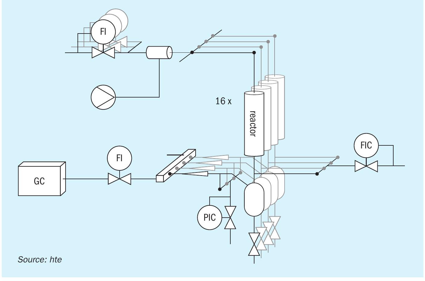
The high throughput approach accelerates catalyst assessment, while offering parallelised testing at a broad range of process parameters. hte’s unique reactor technology enables catalyst testing for NH3 cracking under industrially relevant conditions, including high temperatures (up to 750°C) combined with elevated pressures (up to 50 barg) as well as reliable dosing of trace water, addressing the research gap of current NH3 cracking R&D.
Further research to advance the commercialisation of NH3 cracking within customer projects requires focusing on catalyst stability under different process conditions, which can be supported by hte’s accelerated aging test protocols as well as parallel difference testing.
A versatile 16 fold parallel fixed bed reactor setup similar to a test unit validated and utilised for a recent reverse water-gas shift study was modified for processing NH3. After upgrading the high throughput setup for NH3 processing, the suitability of the unit for this chemistry was demonstrated during validation experiments using an in-house prepared Fe-based catalyst. The high throughput testing equipment (Fig. 1) included mass flow controllers for individual dosing of H2, N2, and Ar, and high-precision syringe pumps for liquid dosing of NH3 and H2O. The feed mixture was distributed equally among the 16 parallel reactors. Catalyst performance testing was conducted using a particle size fraction of the catalyst diluted in inert material to minimise temperature gradients. The reactor effluent gas was analysed using an in-house configured multi-detector online gas chromatograph (GC). Fully automated unit operation and monitoring was realised using hte’s process control software (hteControl). Data evaluation was performed using the myhte software solution, specifically developed for handling large amounts of data produced by high throughput setups.
Experiments were designed to investigate the influence of temperature, pressure, and GHSV on the conversion of NH3 using an Fe-based catalyst via loading of different volumes of the catalyst and performing temperature ramps from 550-750°C at 15 and 40 barg (Fig. 2). The results showed that NH3 conversion increased with temperature, reaching >97% at 750°C and 11,000 h-1 . Increasing GHSV and reactor pressure resulted in reduced NH 3 conversion, which is in line with thermodynamics. The apparent activation energy at low conversion levels was calculated as 140-160 kJ/mol and is comparable with literature values. The blank reactors showed only minimal conversion of <1% up to 700°C and 2% at 750°C, verifying the suitability and inert behaviour of the reactor concept for potential generation of kinetic data sets. Variation of the feed rate by a factor of two and increasing the pressure to 50 barg further expands the parameter field explored during the study, demonstrating the flexibility of the unit.

Additional experiments alongside the temperature screening were conducted to assess the stability and performance of the catalyst. One reactor was maintained at a constant temperature of 650°C to test the performance stability. A run-in behaviour of the catalyst was observed during the startup, emphasising the need for a stabilisation phase when testing catalysts for NH3 cracking under high temperature and pressure conditions. The initial activity of 80% NH3 conversion decreased to around 65% during steady state operation at 40 barg.
As the fitness of the technology and equipment was proven, the high throughput unit was used in subsequent customer projects. One exemplary project involved benchmarking of four different commercial catalysts while screening a wide range of parameters. GHSV was screened in parallel by loading the same catalyst to different volumes. Individual reactor heaters allowed fast screening of temperatures and, furthermore, NH3 feed concentration was varied by flexible dosing of the individual feed components. A lead material was identified, achieving equilibrium NH3 conversion already at 650°C under industrially relevant conditions, demonstrating state-of-the-art properties.
————————————————————————————————————————————–
HERAEUS
Ruthenium catalysts for conversion of ammonia into hydrogen
Ruthenium is a rare and precious metal and is typically a minor component in ores containing platinum group metals (PGMs). The majority of the available ruthenium is obtained as a byproduct in platinum mining, e.g., in Russia, South Africa and Zimbabwe. Such countries have large reserves of PGMs, including ruthenium, and hence represent the main sources worldwide. Heraeus, as a precious metal and global technology group company, has established supply chains and partnerships with various suppliers and is able to ensure a continuous and reliable supply of ruthenium and other precious metals for its products and services. In addition, Heraeus provides refining and a recycling service for PGM processing to meet the demands of customers and clients to reuse valuable natural resources.
Metal recycling offers several benefits:
- Conserves valuable natural resources and less virgin ore needs to be mined.
- Energy savings contribute to reduction of greenhouse gas (GHG) emissions. Recycling of metals avoids significant energy consumption compared to extracting and refining metals from virgin ore.
- Economic impact: the recycling industry provides a source of secondary raw materials, reducing the dependence on imports and promoting local economy.
- Environmental benefits are the reduction of soil erosion, deforestation, and habitat destruction. In addition, water and air pollution associated with mining is avoided.
Heraeus benefits from several decades of experience in recycling services in the field of PGMs and has established a business loop from collecting precious metal waste, to regaining raw metal via recycling, to producing precious metal contained products like catalysts. The regained precious metals are named as secondary or green metals. Heraeus uses green metals, which have a CO2 footprint of less than 98.5% compared to the primary metals, to produce new batch catalysts.
Heraeus ruthenium-based catalysts for ammonia cracking show high catalyst activities at relatively low process temperatures of 400 to 600°C (NH3 conversion reaches close to 100% up to 550°C), compared to commercial Ni-based catalysts with process temperatures of 600 to 800°C (NH3 conversion reaches close to 100% up to 750°C). In addition, Heraeus has improved catalytic activity by systematic studies of, e.g., catalyst support, metal precursors, loading, and dopants. The optimised Ru nanoparticles have a diameter of 6 nm. In studies, two dopants resulted in an improved activity and an increase of 10% in ammonia conversion was observed at 400°C (Fig. 1). This increase in activity of the Ru-based catalysts could be explained by the improved electron donation from the dopants to the support material, which enables charge balancing of the intermediary steps of ammonia cracking.

Heraeus Ru-based catalysts can be supplied in different shapes, e.g., small spheres, medium and large tablets, to fit the application in adiabatic or tube reactors. Customers benefit from the high activity of the catalyst at low process temperatures leading to energy efficiency and reduced total cost of ownership.
—————————————————————————————————————————————
ENERCAT AND LYNAS
Advanced ammonia cracking catalysts
EnerCat, an expert in catalytic formulations and advanced materials solutions, has developed advanced ammonia cracking catalysts which show the best trade-off between NH3 conversion at low temperature (i.e. below 450°C) and a massive reduction of costly Ru particles. It is evidenced that the combination of Ru oxides and rare earth based oxides (such as ceria, CeO2) with a proprietary process leads to a much higher dispersion of the Ru aggregates and much faster reducibility properties as measured by H2-TPR (hydrogen temperature programmed reduction – a technique used for catalyst characterisation). The new advanced catalysts with ultra low loading of Ru show high activity below 500°C and extremely stable performance in a large temperature window. Fig. 1 shows the relation between the temperature at which the Ru oxide crystallites are reduced and the NH3 conversion rate at 400°C for two types of support (alumina vs ceria). These results dismiss the widely held view that the higher the Ru loading, the higher the activity.

Further examination and laboratory trials are needed to better understand the catalytic mechanism and the ‘true’ nature of the active sites. EnerCat and its partner Lynas have already launched some fundamental deep characterisation studies with academics which should lead to additional technical communications soon.
Ru-free catalysts have also been investigated. Fig. 2 shows the NH3 conversion performance of two Ru-free transition metal catalysts. The reference Ni-based catalyst (REF Ni) shows a rather ‘moderate’ activity up to 500°C, in line with the prior art. At 500°C, conversion reaches 80% and over 90% at 550°C. In contrast the innovative transition metal and ceria-based catalyst (ANCC1) achieves 98% conversion from 500°C, offering better performance between 400 and 500°C.

These results confirm the value of combining rare earth oxides and transition metals to initiate the NH 3 decomposition at lower temperatures. Nevertheless, these results show it is difficult, in the absence of noble metals such as Ru, to achieve higher performance levels (>80%) from 400 or 450°C, which remains a priority target for many applications.
————————————————————————————————————————————–
KBR AND CLARIANT
Ammonia cracking catalysts for KBR’s H2ACT SM process
KBR’s approach to commercialising ammonia cracking technology is to develop a flow scheme based on robust risk mitigation strategies, focusing on inherently safe design principles and partnering with world-leading catalyst suppliers such as Clariant to guarantee commercial success.
A block flow diagram for a typical KBR H2ACTSM ammonia cracking plant, including all process unit operations for delivery of high pressure, high purity hydrogen is shown in Fig. 1.

Liquid ammonia from OSBL storage is pumped to the required system pressure. The liquid ammonia feedstock is preheated and vaporised via heat integration within the process. Liquid ammonia vaporisation is also partially provided by excess LP steam available from the small steam system of the ammonia cracking plant.
Vaporised ammonia is preheated via heat integration in the process and subsequently by recovering heat from the convection section of the fuel fired ammonia cracker, before being directed to the reactor system for dissociation.
The reactor system consists of an adiabatic dissociation reactor (pre-cracker) in series with an isothermal, fuel-fired cracker (ammonia cracking furnace or ammonia cracker). The cracking reaction is performed under presence of catalyst in both reactors – with catalyst formulation optimized for each reactor characteristics and application.
All ammonia dissociation (for both reactors) is driven by heat from the fuel-fired ammonia cracker. The ammonia cracking furnace design is based on the well-proven KBR down-fired primary reformer design with hundreds of references in ammonia production, from small to large scale capacity and decades of experience and knowhow.
The heat source for the ammonia cracking furnace is fuel from the process, consisting of tail gas from the hydrogen purification section, supplemented by cracked gas (H2 /N2) (or optionally supplemented by natural gas).
The ammonia cracking furnace is designed to attain maximum thermal efficiency by utilising process waste gases as part of the fuel, as well as by recovering heat in the convection section from the flue gases for feed vaporisation, preheat and dissociation.
The furnace convection section is furnished with a selective catalytic reduction (SCR) system as standard, able to meet the most stringent environmental emission requirements.
Cracked product purification is based on well-proven and often-used processes:
- Ammonia recovery by a simple water-based ammonia absorption/distillation unit, designed and in operation in a multitude of KBR ammonia plants worldwide. After this unit, the hydrogen purity is 75 mol-% dry.
- Nitrogen removal using standard pressure swing adsorption (PSA), a proven, reliable and cost-effective technology used in a variety of industries.
Including these units, the hydrogen product can be delivered at any purity >99.97 mol-%. Hydrogen purity requirement can vary significantly depending on the hydrogen product off-taker. For a centralised large-scale cracking unit, any proportion of the product can be sent to an additional purification unit (PSA) for further nitrogen removal, for example, to produce very high purity hydrogen for mobility applications.
Typical hydrogen delivery pressure of around 30 barg is achievable without additional hydrogen compression. For higher delivery pressure, a hydrogen compressor is included in the flow scheme.
Scale and performance
H2ACTSM can deliver hydrogen at mega scale and any purity depending on the industrial application. The performance of the H2ACTSM ammonia cracking plant is consistently maintained across the entire capacity range, from small to mega-scale production, and across the operating envelope of the plant.
Clariant catalysts for ammonia cracking
Clariant has developed and offers highly innovative catalysts for ammonia cracking. Clariant has over 40 years of experience in manufacturing ammonia cracking catalysts for the small-scale cracking units in the market today. Coupled with Clariant’s long history in providing nickel-based catalysts for steam methane reforming, Clariant is ideally positioned to offer catalysts for the ammonia cracking market with high technology readiness, established manufacturing and high performance.
Clariant’s ammonia cracking catalyst portfolio comprises the following:
- HyProGen® 830 DCARB: A nickel-based catalyst designed for high temperature applications (up to 750°C). Due to its mechanical robustness, it can be used in reformer-type fired tubular reactors.
- HyProGen® 820 / 821 DCARB: A nickel-based catalyst designed for moderate-temperature applications (420 to 650°C) in adiabatic reactors. Combines superior activity with high thermal resistance against deactivation.
- HyProGen® 850 DCARB: A highly active ruthenium-based catalyst designed for low temperature applications (400 to 600°C). Suitable for smaller and more compact plant designs.
Clariant catalyst testing for H2ACTSM
Clariant is running an ongoing R&D program in order to ensure that the catalysts show excellent activity and stability under the conditions of H2ACTSM . Hence, all tests are performed at relevant conditions in alignment with KBR, e.g., pressures up to 40 bar and realistic feed composition with 2,000 to 5,000 ppm water.
H2ACTSM comprises two reactors, a pre-cracker and the fired tubular main cracker (ammonia cracking furnace). Two completely different types of catalysts must be applied to address the needs and requirements of each reactor.
Pre-cracker (adiabatic reactor)
In the pre-cracker of H2ACTSM , highly active bulk nickel catalysts can be applied as mechanical stability requirements are lower for this type of reactor. A two-layer concept is applied with a top layer of HyProGen 820 DCARB, which has high thermal stability, and a bottom layer of the highly active HyPro-Gen 821 DCARB, which offers an efficient alternative to ruthenium-based catalysts.
While ruthenium-based catalysts are typically sensitive to water, especially at high pressure and temperature, Clariant’s nickel pre-cracking catalysts are very robust in the presence of water.
Ruthenium-based catalysts have two additional drawbacks compared to nickel-based catalysts: Firstly, they suffer from rapid deactivation at moderate to high temperatures. Secondly, the activity of ruthenium declines strongly with pressure: Fig. 2 shows that the activity of Ni-based HyProGen 821 DCARB is close to the 2 wt-% Ru benchmark at 40 bar.

In order to study the robustness of the catalysts against thermal deactivation under H2ACTSM conditions, several rapid ageing tests were performed. Typically, such tests are performed at temperatures roughly 50 to 100 °C higher than the operating conditions in order to observe the catalytic activity over time and evaluate the expected lifetime and performance. In most catalytic processes two stages of deactivation can be detected: a fast initial deactivation followed by a relative stabilisation of the performance. In order to determine if the catalytic activity reaches a stable state, the test must be sufficiently long. Therefore, up to eight aging cycles were performed. In the case of HyProGen 820, DCARB aging was performed at 750°C, hence around 100°C higher than the maximum expected operating temperatures. Stable performance was achieved after five ageing cycles. Analogous tests were performed with HyProGen 821 DCARB at lower temperatures.
Fired tubular reactor (ammonia cracking furnace)
In the fired multi-tubular-reactor of H2ACTSM , the main conversion will occur at temperatures up to 700°C. For this type of application, the catalyst needs to show good activity and more importantly, excellent mechanical stability as well as a low pressure drop. Clariant has been producing such catalysts since the 1950s for use in steam reforming applications at temperatures over 800°C and pressures exceeding 40 bar.
HyProGen 830 DCARB combines high activity with good thermal stability. Furthermore, this catalyst has already been proven in commercial fired multi-tubular reactors, showing tremendous mechanical stability.
In order also to prove the long-term stability of HyProGen 830 DCARB, additional rapid ageing tests were performed which showed the initial deactivation was quite small, and a highly stable performance was achieved after just four ageing cycles, showcasing the excellent thermal stability of HyProGen 830 DCARB.
To prove the catalyst performance under H2ACT conditions in the main cracker, a modified feed composition was used which mimics the real inlet composition of the main cracker: HyProGen 830 DCARB achieves nearly 99% NH3 conversion at 675°C, approaching the thermodynamic equilibrium at both start of run and after eight subsequent ageing cycles (at 750°C).
In summary, combining Clariant’s catalyst expertise with KBR’s technology and equipment capabilities offers an effective and low-risk solution for ammonia dissociation into hydrogen, and mitigates risks for commercial ammonia cracking projects, completing the sustainable ammonia to hydrogen value chain.
———————————————————————————————————————————–
JGC GROUP
Technology development and demonstration of ammonia cracking
JGC, Kubota, and Taiyo Nippon Sanso are jointly carrying out an R&D project on large-scale ammonia cracking technology for low-carbon hydrogen production by a tubular ammonia cracking furnace as part of NEDO’s development of technologies for building a competitive hydrogen supply chain.
JGC’s scope is to supervise the project, design and develop the entire ammonia cracking process and furnace, plan the demonstration, and estimate the costs, targeting a large-scale, highly efficient and zero-emission ammonia cracking system in the order of 100,000 t H2 /year capacity for a commercial plant in around 2030. Kubota’s scope is to research and develop ammonia cracking tubes, while Taiyo Nippon Sanso will research and develop hydrogen gas purification systems (PSA). In addition, JGC is outsourcing research to Idemitsu Kosan to support with examination of the demonstration site and planning of the demonstration phase.
The product hydrogen specification will determine the optimum ammonia cracking conditions and key design parameters such as cracking temperature and pressure and hydrogen purification inlet and outlet conditions.
The cracking temperature and pressure, in particular, will have a huge influence on the ammonia conversion rate and therefore residual ammonia, which may have an impact on the hydrogen recovery rate of the hydrogen purification unit.
If a higher temperature is selected, the conversion rate will be higher, but it will require higher fuel consumption and higher grade of cracking tube material or thicker cracking tube. If a lower pressure is selected, the conversion rate will be higher, but it will require more power consumption to compress product hydrogen to meet the users’ requirement.
To speed up time to commercialisation, existing technologies will be utilised as much as possible. However, there are some areas of research and development required for commercialisation.
One important area of investigation is the issue of nitride corrosion in cracking tubes and process piping, which needs to be carefully addressed, since it will have huge impact on the reliability and lifetime of the system. In addition, tube materials with high creep rupture strength are required, suitable for high-temperature and high-pressure environments over a long lifetime. Kubota is analysing resistance to nitriding for an existing tube line-up. In addition, Kubota is developing materials dedicated to ammonia cracking tubes (see Fig. 1).

A second area of focus is hydrogen purification by PSA to remove nitrogen, residual ammonia and water in order to meet the product hydrogen specification. The influence of residual ammonia on hydrogen recovery rate needs to be addressed, since it may have an impact on the overall energy efficiency.
Project status and demonstration plan
The ammonia cracking demonstration site will be at Idemitsu Kosan’s former refinery site in Yamaguchi Pref., Japan. The FEED for the demonstration plant will be carried out in 2024, with the aim to propose the demonstration project to NEDO in 2025.
—————————————————————————————————————————————–
JOHNSON MATTHEY
Johnson Matthey’s world scale ammonia cracking process
Johnson Matthey (JM) has developed an ammonia cracking process which is suitable for deployment for large scale hydrogen (or cracked gas) production. It has been developed using JM’s core competencies of catalyst design, process design and chemical plant scale up to de-risk the technology.
The key unit operations are the ammonia cracker which decomposes ammonia to hydrogen and nitrogen, and the separation system which purifies the hydrogen product. The ammonia cracking reactor is similar in principle to a steam-methane reformer (SMR), and JM has applied significant experience from its market leading position in designing SMR’s for the methanol industry. Sensible and reaction heat is supplied to the process via combustion of a fuel. Heat is recovered at the exit of the cracker and exit of the flue duct through heat integration within the process; this is a common approach within SMR based processes which has been adapted to the lower temperature conditions associated with the ammonia cracking flowsheet. Abatement technologies are installed within the flue duct to minimise emissions such as NOx and N2O.
In a departure from established technologies, JM’s ammonia cracker is fuelled by a blend of ammonia, hydrogen, and nitrogen. This removes the requirement for an external fuel or energy source, with the fuel derived from the pressure swing adsorption (PSA) tail gas and a portion of the ammonia fed to plant. JM has tested the combustion characteristics of these novel fuel blends, gaining insight into the flame characteristics and emissions associated with the departure from combusting natural gas. To purify the hydrogen stream, a combination of ammonia scrubbing, and pressure swing adsorption have been selected, with both technologies proven at scale in similar industrial applications.
JM ammonia cracker
JM offers a top-fired ammonia cracker which has been developed from JM’s world leading design for large scale SMRs. Key changes include catalyst and reaction chemistry, fuel composition, environmental controls, and metallurgy. Heat recovery from the flue duct has been configured to accommodate efficiency, controllability, operability, and capital cost considerations.
Catalyst selection
The cracker uses JM’s established range of KATALCO 27 series of ammonia cracking catalysts, which have been offered commercially for over 50 years.
KATALCO 27-200MQ is a nickel-based, high activity, ammonia cracking catalyst. The QUADRALOBE shape enhances radial heat transfer across the tube, and the shape of the pellet reduces pressure drop growth with time on-line.
Within a multi-tubular reactor, such as an ammonia cracker, the burners provide radiant and convective heat to the tubes. The endothermic nature of the ammonia cracking reaction leads to a radial temperature gradient across the catalyst filled tubes. The catalyst pellets help mix the bulk gas, promote heat transfer and minimise the aforementioned radial heat gradient within the tube. Formation of a gas film at the tube wall limits heat transfer, however, this can be managed with the correct catalyst pellet shape and size. A catalyst with good packing can disrupt the gas flow by causing more turbulent flow. By having a smaller gas film more heat is transferred into the catalyst to drive the endothermic reaction which can result in lower tube wall temperatures and a more efficient process.
Concerns have been expressed by the industry that the relatively small amounts of moisture contained within merchant ammonia can deactivate certain types of ammonia cracking catalyst. JM has conducted testing to confirm that this is not the case with KATALCO 27 series.
JM is also investing in extensive characterisation of the ammonia cracking reaction both for product development and to better understand aspects such as reaction kinetics, product activation and chemical inhibition. The driver for this work is that whilst existing small-scale applications can tolerate a degree of under or over performance, relatively small changes in performance will be critical to the economics of world scale ammonia cracking plants and it is essential that sufficient knowhow exists to allow such plants to be optimised at the design stage.
Ammonia combustion
Ammonia has been proposed as a fuel for many years. Although having a reputation for being difficult to burn and for generating high concentrations of nitrogen oxides there are some obvious advantages for deploying it as a fuel in an ammonia cracking process.
The use of ammonia as a fuel leads to synergistic benefits in that the process is more tolerant to ammonia slip from the cracker and there is no necessity for a high efficiency PSA unit. This is because, ammonia slip from the cracker and PSA off gas can be used as fuel for the ammonia cracker. The ammonia fuel saved can then be used as feedstock. Emission levels <0.1kg CO2e/kgH2 can be achieved.
JM has commissioned full scale burner tests to verify the practicality of using ammonia as a fuel and to confirm emission levels. These have been carried out under a wide range of conditions including start-up, shutdown, and normal operation.
The results have been used to validate JM’s design tools for use in designing ammonia crackers.
Ammonium nitrate and ammonium nitrite
Ammonium nitrate, and ammonium nitrite, can form when both ammonia and NOx are present at relatively low temperatures. Under the right circumstances, both can be explosive and there are many publicised examples in the nitric acid industry.
Although there should be little prospect of forming such substances during normal operation JM has mapped out a safe operating window which considers failure conditions and forms the basis of its ammonia cracker design. JM has also filed patent applications on the topic.
Metallurgy
JM has selected metallurgies that have been demonstrated in relevant service and has also used computational materials engineering to further its understanding of alloy degradation under ammonia cracking service. In addition, JM is conducting materials test work to further validate and enhance its understanding of the performance of alloys in ammonia cracking service. Patent applications have also been filed relating to techniques which can be used to reduce the severity of nitriding.
Emission control
JM is a leader in emissions control technology and is ideally placed to optimise the development and placement of emission control products within an ammonia cracking flowsheet. The pollutants of concern are acid forming oxides of nitrogen, ammonia and nitrous oxide and JM has solutions to meet regulatory requirements.
- Acid forming oxides of nitrogen (NOx): As might be expected, the presence of ammonia in a fuel tends to promote the formation of NOx. In JM’s ammonia cracking process, the resulting NOx concentration remains within JM’s range of experience and abatement solutions are available to achieve any known regulatory standard.
- Ammonia (NH3): JM has offered ammonia abatement products for many years and JM’s abatement solution design meets known regulatory standards.
- Nitrous oxide (N2O): JM has offered N2O abatement products for many years. Test work has been carried out to extend the operating window of an existing product to allow optimised N2O abatement within an ammonia cracking flowsheet.
Cyclic operation
Cyclic operation poses a challenge in terms of both mechanical integrity and catalyst longevity. JM’s ammonia cracking process has been designed to accommodate the fluctuations in plant load that will be required in a renewables powered economy.
Ammonia removal
JM chooses to remove ammonia upstream of the PSA unit. This has the advantage of allowing the PSA unit to be designed and optimised to remove less strongly adsorbed substances such as nitrogen. The ammonia that is recovered is used as fuel in the ammonia cracker, the net result being that overall performance of the plant is only weakly dependent on the performance of the ammonia cracker.
Pressure swing adsorption
Separation of hydrogen from the cracked gas stream is critical to achieve the required purity of the product stream.
PSA is a well-established separation technology that is proven at scale required for this flowsheet and can achieve hydrogen recovery rates of 90% or above. PSA units are used in existing hydrogen production plants and can achieve the required hydrogen purity level for this application.
The tail gas from the PSA unit contains nitrogen, unrecovered hydrogen and residual ammonia and is used as a fuel source for the ammonia cracker. PSA is selected over other types of gas separation processes due to the high capacity of unit required and high purity of hydrogen product (>99.96 mol-% can be achieved).
Reference: Pach J. (Johnson Matthey): “World scale ammonia cracking”, presented at Nitrogen+Syngas 2024, Gothenburg, Sweden, 4-6 March 2024.
—————————————————————————————————————————————–
TECHNIP ENERGIES
Low energy intensity ammonia cracking
Technip Energies (T.EN), with a 60 year track record in technology development, innovation and EPC project delivery is poised to supply highly-competitive solutions to any hydrogen producer, on both low-carbon and carbon-free platforms. T.EN, a leader in the acceleration of the energy transition, is introducing its patented and scalable high-efficiency ammonia cracking solution.
The selection of proven catalyst is a cornerstone of the T.EN cracking process and ensures robust performance of the process. The catalyst selection for this application is a well-proven commercial catalyst platform designed for high-temperature applications. It combines excellent activity with very high thermal stability over a wide operating range.
The T.EN technology utilises a high-grade heat recovery, or “recuperative” concept. The highest value heat contained in the cracked gas is directly recovered and diverted back towards the reaction zone sustaining the cracking reaction. The design of the recuperative catalyst tube achieves simultaneously higher throughput and higher heat recovery in the integrated process compared to a conventional pellet-packed tubular reactor layout.
Downstream of the ammonia cracking process, the cracked gas comprises mainly a hydrogen/nitrogen mixture, plus a small amount of unconverted ammonia. The mixture is cooled and purified to reach the desired product specifications. The product purification unit can be customised based on client/off-taker needs to achieve a hydrogen purity of 99.9% or more.
Zero carbon footprint is achieved via combustion of carbon-free fuel, i.e. ammonia, hydrogen/nitrogen fuel mixture and/or pure hydrogen.
Key performance indicators
Technip Energies’ high-efficiency ammonia cracking process minimises heat loss, maximises exergy, and minimises external energy supply, thus maximising the energy efficiency of the process. Table 1 summarises the key performance indicators for the process.

Hydrogen purity may vary between 75 to 99.9+% depending on end-user application requirements.
Key benefits
Ammonia cracking is an endothermic process, meaning it requires energy input to sustain the reaction. Unlike the steam-methane reforming process, ammonia cracking does not mandate steam generation. In conventional hydrogen production, steam is required as feed to the process. Steam is needed to sustain feedstock conversion, to manage carbon formation, and to sustain the water-gas shift reaction. Thus, for hydrogen production, the valorisation of available energy in the form of incremental steam production may make economic sense, as it helps to achieve both high overall thermal efficiency and low specific conversion energy.
Steam is not required to sustain the ammonia cracking reaction or process, and therefore diversion of feed and fuel energy towards raising (export) steam correlates to additional systems and equipment, process complexity, and introduces a second energetic product. Therefore, the incentive is high to absolutely minimise the portion of energy invested to produce hydrogen, and economics are generally enhanced by maximising conversion of ammonia to product hydrogen. By optimising process heat integration, including T.EN’s recuperative technology features, steam production and systems are completely eliminated, while the thermal efficiency is maximised. On the contrary, where steam co-production is advantageous, these features are simply added back, being analogous to conventional hydrogen production unit features.
Described another way, Technip Energies’ high-efficiency ammonia cracking process offers the opportunity to utilise high-grade heat to make hydrogen, not byproducts, and to unlock incremental cracking efficiency.
Process heat integration is maximised by exploiting “pinch” principles. Avoiding a steam generation system in the process eliminates “flat spots” which inevitably lead to large temperature approaches, and exergy loss. Downgrade of valuable high-temperature heat to steam generation is avoided (i.e. a very large 750°C vs. 250°C temperature approach). Furthermore, process integration leads to reduced fuel-firing demand, a smaller main reactor, and minimum conversion energy. Simultaneously maximising efficiency, maximising yield and minimising fuel demand combine to ultimately pay out as lower cost of production.
Experience
Having already successfully cracked ammonia at various scales for hydrogen production in refinery and utility settings, Technip Energies is accelerating the roll-out of ammonia cracking solutions. Combining decades of expertise in high-temperature process systems and equipment – particularly around hydrogen production, steam-methane reformers, steam cracking, ammonia plants and high-temperature processes in general – T.EN has a proven track record to deliver hydrogen from ammonia sources:
- Ammonia cracking for start-up of world scale hydrogen plants
- Ammonia cracking for supplying hydrogen to de-oxo units
- Recuperative reactor solutions, suitable for ammonia cracking (TPR and EARTH® )
- Steam methane reforming (SMR) with > 275 plants worldwide
- Customised catalyst co-development for EARTH®
- Ultra-low NOx burners (LSV® and TSWB® )
- Delivery of fully modularised plants
——————————————————————————————————————————————
THYSSENKRUPP UHDE
Optimisation of the ammonia decomposition process
thyssenkrupp Uhde offers all steps of the process chain for ammonia decomposition or cracking to hydrogen (green or blue hydrogen – ammonia synthesis – ammonia decomposition to hydrogen) and has investigated various technical options for the ammonia decomposition process. Different process configurations have been assessed for their effect on energy efficiency and CO2 intensity, which, among others, also depend on the selection of the process heat source. This also impacts the decision between centralised and localised hydrogen production.
Three process configurations were investigated in more detail and are discussed here, distinguished by the type of energy supply:
- Case 1: Self-sustaining process: The required energy is provided by the combustion of a part of the feed and/or product stream.
- Case 2: Process with external fuel source. The required energy is provided by combustion of a fuel supplied from outside.
- Case 3: Process with electrical heating. The required energy is provided by electric heaters.
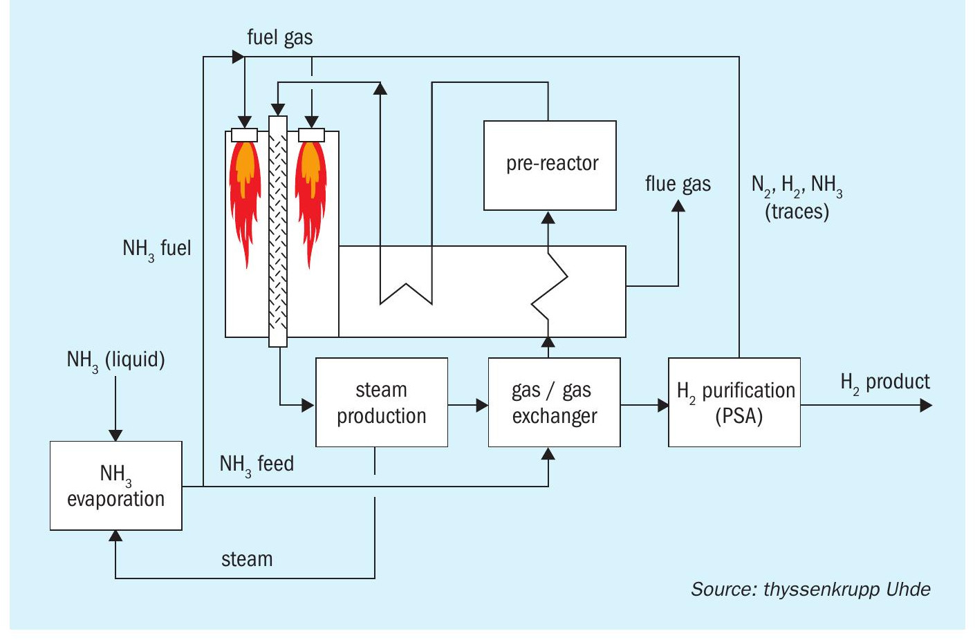
Fig. 1 shows a simplified flowsheet for Case 1. A pre-reactor has been added to enhance the efficiency. The other cases are derived from Case 1:
- Case 2: No use of NH3 for firing, replaced by natural gas firing instead.
- Case 3: Adiabatic reactors with intermediate electrical heating, fired heater for utilisation of PSA off-gas, no use of NH3 for firing.
All processes are designed in such a way that they do not export any off-gas or steam. Waste heat is utilised by the process as far as reasonably possible. The battery limit conditions are set as per Table 1.

Efficiency comparison
Table 2 shows a qualitative comparison of the processes.

A quantitative analysis is provided in Table 3. In all cases, the theoretical total H2 content of the input is 2,198 kmol/h.
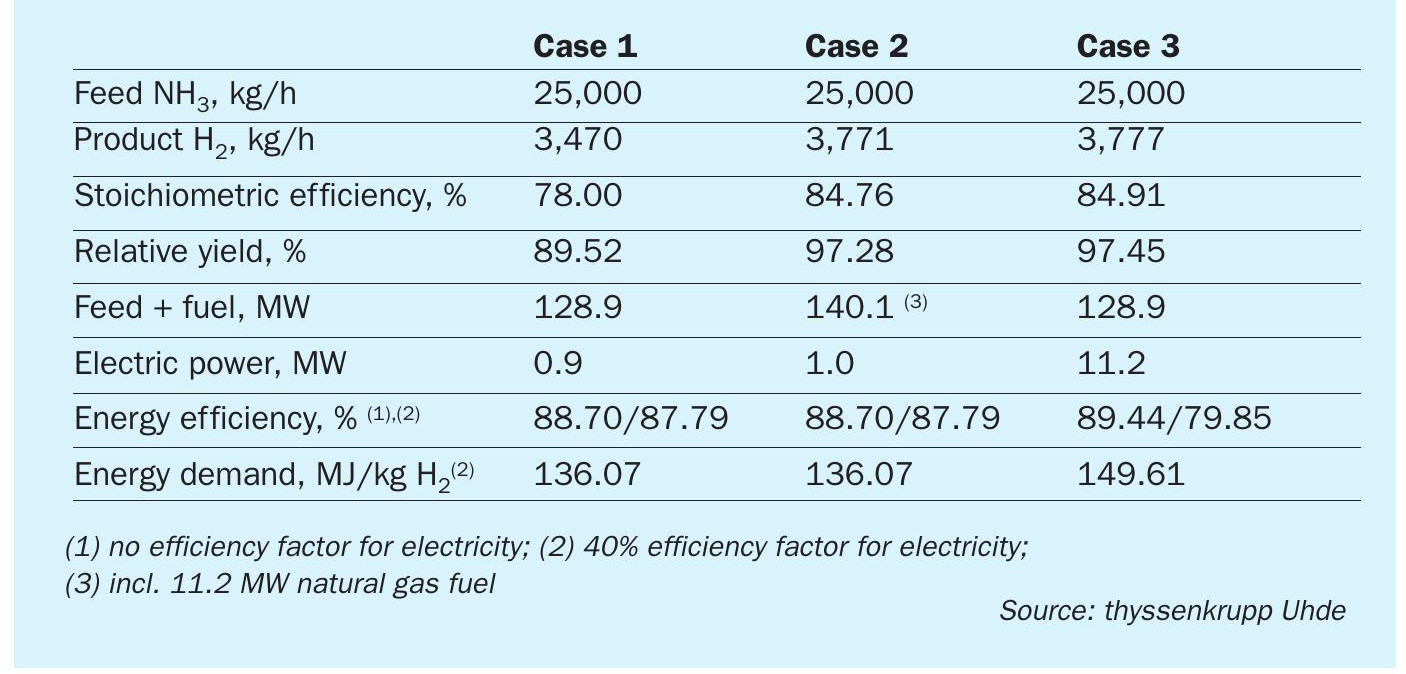
The efficiency of the basic process has been improved by adding an adiabatic pre-reactor. This also helps to solve some design challenges. The efficiency increase mainly originates from lower overall firing duty and less heat loss with the flue gas. The pre-reactor design is therefore also adopted in Case 2.
The stoichiometric efficiency from Case 1 can be increased if less feed/product is used for heating by replacing it with another fuel or electricity. This is done in Cases 2 and 3. The theoretical maximum plant yield is therefore determined by the hydrogen yield of the pressure swing adsorption unit. However, this does not necessarily increase the energy efficiency.
For a process consuming fuel and electric power, electric power input is handled by considering a specific conversion efficiency when the combustion of a fuel produces electric power.
All of the above processes consume a small amount of electricity for pump and compressor power. In Cases 1 and 2, the electric power supply is only 0.7% of the total energy of the process. In Case 3 however, a significant amount (8%) of the energy comes as electric power, and its proper valuation has a significant impact on the efficiency figure. For Table 3, 40% conversion efficiency has been used.
For comparison, H2 production by steam methane reforming has an energy consumption of approx. 140 MJ/kg, expressed by the natural gas LHV.
All processes generate an off-gas stream containing unconverted ammonia. In Cases 1 and 2 this is sent to the cracker firing. Since this is an attractive solution, this is also done in Case 3, i.e. this process includes firing, and only part of the energy is supplied by electric power. The high electricity consumption of Case 3 per ton of H2 produced (Table 3) is about 9% of that of the production of the same amount of H2 by water electrolysis.
CO2 greenhouse gas emission
CO2 greenhouse gas (GHG) emissions for the whole process chain of ammonia production and cracking has been compared by assuming different production pathways (green and blue) for the ammonia fed to the cracking processes (Cases 1, 2, 3), whereby each cracking process can be differentiated again by the CO2 load of the electric power used (e.g., renewables only vs. average grid).
To achieve a low CO2 footprint, the ammonia has to be either green or blue. Specific CO2 emissions for ammonia production are:
- Green ammonia: Ammonia from hydrogen via water electrolysis and nitrogen via air separation, both driven by renewable power. No GHG emission by the ammonia process and electricity generation, but GHG emission associated with the installation of the facility, e.g., in a wind farm: 0.112 kg CO2 /kg NH3 .
- Blue ammonia: Ammonia from steam reforming of natural gas, CO2 emissions reduced by CO2 capture and sequestration: 0.2 kg CO2 /kg NH3 . Expressed as hydrogen, this would mean 1.1 kg CO2 / kg H2 , which would satisfy the conditions of being below 2.0 defined by the US Infrastructure Bill 2021 for “clean hydrogen”. There is no unique definition and CO2 emission standard because several degrees of CO2 capture are possible.
For comparison, a convectional ammonia plant based on steam reforming of natural gas has a CO2 emission of about 1.7 kg CO2 /kg NH3.
Since the purpose of using ammonia as a hydrogen carrier is based on the idea that ammonia is produced in a place where renewable power is abundantly available at a low cost, and it is transported to a place where such renewable power is expensive (like Europe), it is a realistic assumption that renewable power is available in a limited amount and at a high cost only at the cracker location.
Table 4 compares the resulting specific emission factors for the full process chains (basis: CO2 equivalent of electric power for wind and grid mix (Germany 2018) = 0.0112 and 0.5 kg CO2 /kWh respectively).

For Case 2, a comparison with Case 1 shows that heating by natural gas increases the CO2 emission by about 0.5 kg CO2 /kg H2 .
For Case 3, a comparison with Case 1 shows that electric heating has a small net CO2 saving if cracking power is from renewable sources. There is a significant increase if it is taken as a grid mix.
Process variants
The flowsheet from Fig. 1 can be modified to match certain special applications, for example:
- Steam export: If the ammonia cracking plant is co-located with a steam consuming facility, the firing of the furnace can be increased in order to make more waste heat available for steam generation and superheating.
- Use of hydrogen/nitrogen mixture: In certain applications where hydrogen shall be used as a fuel, it might not be required to separate the nitrogen. In this case, the “hydrogen purification” step can be omitted and the gas from the cracker outlet can be used.
- Integration into a gas turbine process: An application of hydrogen use might be its combustion in a stationary gas turbine, e.g., for power generation. If the gas turbine is part of a cogeneration process (production of steam from hot turbine exhaust gases and consumption in a steam turbine), the waste heat from the cracker can be integrated into this process by using it for additional steam generation and/or superheating.
Centralised vs. local H2 production
Centralised and localised hydrogen production both have their pros and cons as regards safety, economic feasibility and CO2 avoidance. The safety of both options strongly depends on the selections made for inland transport and storage of ammonia and hydrogen, while process economics, highest energy efficiency and avoidance of CO2 emissions favour ammonia cracking in large, centralised units.
—————————————————————————————————————————————-
CASALE SA
Novel ammonia cracking technology for the global energy transition
Leader in technological innovation, Casale aims to play an active role in the energy transition continuously enriching its portfolio with new advanced sustainable solutions including its latest next generation ammonia cracking technology.
Developed in cooperation with market-leading catalyst manufacturers, the process is based on Casale’s long and successful experience in material selection for processes operated in environments rich in ammonia and hydrogen at high pressure and temperature, minimising the technology risk.
Covered by two patents, the new Casale ammonia cracking technology was first launched in 2021 and has continued to be improved and optimised over time to cover all specific client needs in terms of performance and cost.
Different process configurations for a wide range of single train plant capacities have been studied and developed from the completely self-sustaining scheme to the low-carbon scheme.
During the Nitrogen + Syngas 2024 Conference, Casale took the opportunity to formally launch the trade name of its ammonia cracking technology, MACH2, which stands for Mega Ammonia Cracking for H2 production.
Casale ammonia cracking technology offers the highest single train plant capacity on the market, covering a wide range of hydrogen plant capacities, ranging from 5 t/d to 1,300 t/d of pure hydrogen (up to Grade 5 hydrogen purity).
Fig. 1 shows a simplified block flow diagrams of Casale’s self-sustaining scheme.

The process scheme consists of four main sections: feed preheating and pretreatment, ammonia cracking, ammonia recovery and product purification. In the preheating and pretreatment section, liquid ammonia is vaporised and preheated up to the temperature required for the reaction. The preheated ammonia then reaches the core unit, the ammonia cracking section, where the ammonia decomposition takes place. The resulting cracked gas is finally sent to the hydrogen purification section, consisting of well-known and proven technologies commonly used in different industrial processes:
- Ammonia recovery unit based on H2O/NH3 absorption and distillation technologies where unconverted ammonia is recovered and recycled to reduce consumption.
- Hydrogen PSA unit where the H2 is recovered and purified up to the required level.
The process scheme can be customised and optimised according to customer needs (capex vs opex).
Casale ammonia cracking reactor
Casale has developed different ammonia cracking reactor design concepts and configurations depending on the size of the hydrogen production plant.
Its ammonia cracking unit is mainly composed of a combination of adiabatic cracker reactors and an ammonia cracking furnace. The ammonia cracker design duplicates concepts from proven reaction furnace designs, like the steam methane reformer, wherever practical, coupled with Casale unique revamping expertise on all existing SMR types and configurations and know-how on material behaviour when exposed to an ammonia and hydrogen environment (creep, hydrogen attack, nitriding). This places Casale in the unmatched position to be able to always select the best engineering solution for every component of the ammonia cracker furnace to ensure the highest reliability.
Technology readiness level (TRL)
All unit operations in the ammonia cracking scheme reach the highest technology readiness level (TRL 9) except for the ammonia cracking catalyst (TRL 7) as its technology is only mature for small-scale systems. Large-scale applications are still being validated and tested by major catalyst manufacturers for further optimisation and improvements.
As the testing and validation proceeds, proving its operation in dedicated demo units, the catalyst TRL level is inevitably destined to rise, reaching the maximum level when the first large-scale plant is built.
Scalability of the Casale ammonia cracking plant is mainly limited by the performance of current catalysts available on the market rather than the catalytic furnace unit size.
Casale ammonia cracking KPIs
The main key performance indicators (KPIs) for the two main Casale process schemes valid for the entire single train plant capacity range are provided in Table 1.

The self-sustaining (CO2 free) scheme is dedicated to large capacity in which a small quantity of hydrogen product is used as make-up fuel.
The low-carbon alternative considers both the case of complete heat balance with external fuel and the case in which a fixed amount of the cracked gas at the PSA inlet is burned with a minimum external fuel gas contribution for control purpose. Pure methane has been considered for the performance evaluation.
The contribution of cracked gas leads to a higher ammonia feed consumption, as part of the feed is used as fuel, while minimising CO2 emissions. Conversely, the complete use of external NG fuel as make-up allows the ammonia feed consumption to be decreased, but results in a higher CO2 emission.
Key performance indicators are affected by specific project requirements in terms of hydrogen purity, carbon intensity, product delivery pressure, utilities system, capex vs opex optimisation, etc.
Thanks to its background and experience, Casale can provide a simple, flexible and customised technology which can be tailored to specific plant needs with a well proven solution that is immediately available.
Improving and optimising catalyst performance for large-scale ammonia cracking units is fundamental for further process improvements and Casale is highly engaged in continuously evaluating the most promising and new-generation catalysts to implement in its own technology to continue to provide the best technological solutions for a better future.