Nitrogen+Syngas 390 Jul-Aug 2024
31 July 2024
Reliability of reformer outlet systems
STEAM METHANE REFORMING
Reliability of reformer outlet systems
The reliability of primary reformers is a key issue for syngas plants. In this article O. Chung, N. Goodman and C. Thomas of Quest Integrity describe the damage mechanisms and material limitations that impact the reliability of reformer outlet systems and the improvements that may be implemented.
The primary reformer in petrochemical plants is a critical asset that enables the conversion of hydrocarbons (e.g. natural gas or methane) into hydrogen-rich synthesis gas (syngas). The main chemical reactions to generate syngas occur within a reformer furnace, which contains spun cast HP50 tubes filled with a catalyst. The main damage mechanism for these catalyst tubes is creep from internal pressure. Literature is available to describe the metallurgical changes that occur for HP50 catalyst tubes, the effect this has on HP50 creep properties and the life assessment methodology based on this understanding1,2.
Downstream of the reformer furnace is the hot collection system. This outlet system typically consists of the following equipment:
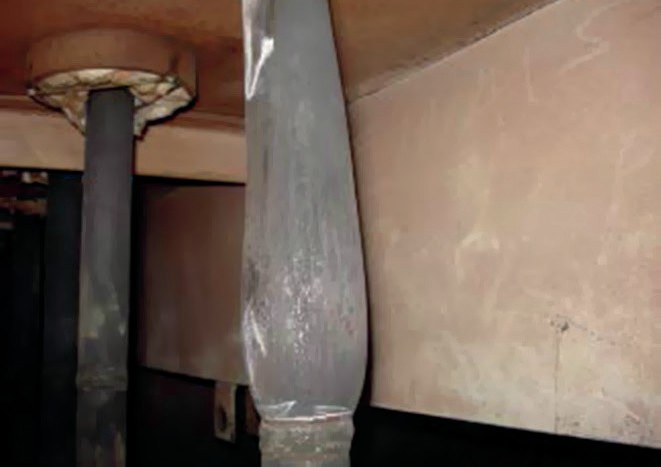
- outlet pigtails – small diameter tubing, known as pigtails due to their often convoluted geometry, is used to accommodate for thermal expansion between the large catalyst tubes and manifolds during start-up and shutdown;
- manifolds;
- bull-tees.
A schematic showing an example of a hot collector system and materials of construction is shown in Fig. 1.

The hot collector system is equally as important as the catalyst tubes because the equipment operates at a sufficiently elevated temperature for creep to occur and complex stresses are generated during operation. Methods used to assess fitness for service and remaining life of high temperature components are well-established and are embodied in codes such as API 579-1/ ASME FFS-1 “Fitness-For-Service” (API 579)3. However, metallurgical factors such as in-service changes to the materials used for the hot collector equipment and other damage mechanisms not accounted for in the design of the hot collector system present additional aspects to incorporate into the assessment. There is a need to understand the useful remaining life of these components to ensure continued safe operation and reliability, especially for an aging plant.
This article discusses other damage mechanisms and metallurgical factors not accounted for in the design of reformer hot collector systems and the material limitations that affect a fitness for service assessment.
Outlet pigtails
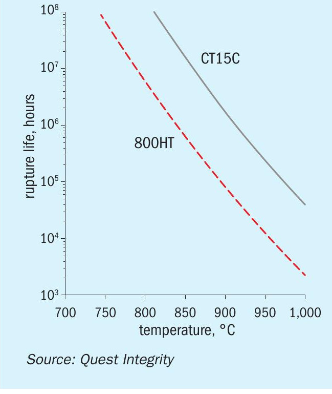
Outlet pigtails are predominantly fabricated from Alloy 800H, Alloy 800HT or their proprietary variants. The nominal material properties for Alloy 800, Alloy 800H and Alloy 800HT, as specified in ASTM B407, are summarised in Table 14. The outlet pigtails may also be dual specified as Alloy 800H/800HT due to the similarities in the nominal specifications.
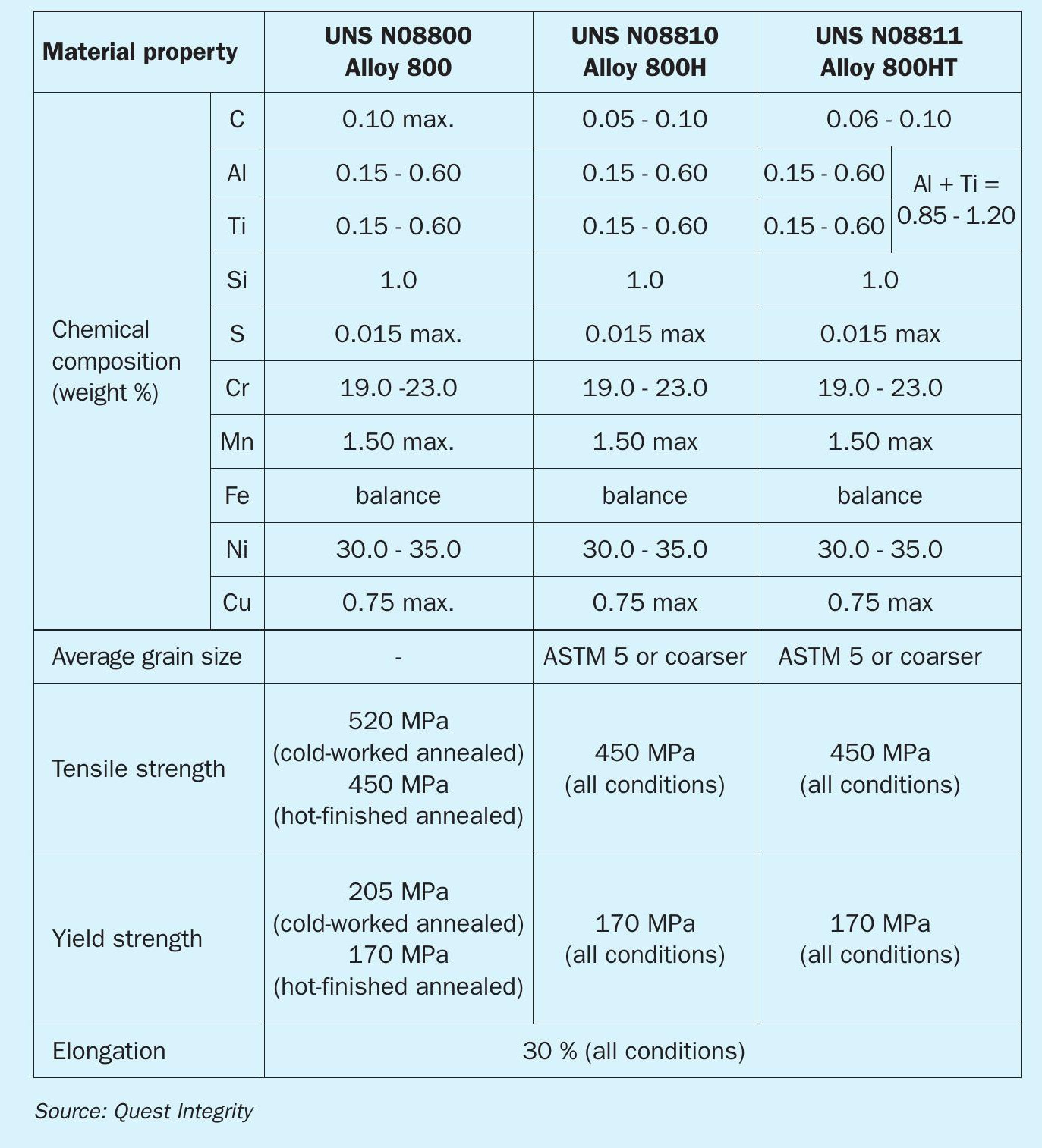
Alloy 800 was developed from high value but scrap Nimonic (nickel-chromium) alloys with additions of aluminium and/or titanium and diluted with iron5 . The Nimonic alloy contained significant levels of aluminium and titanium, which effectively became contaminants in the resulting Alloy 800. Nonetheless, these elements are reported to generate benefits despite a drop in ductility between 650 °C and 750 °C6. The 800H and 800HT variants are modifications that offer improved material properties over Alloy 800. These are as follows6:
- 800H: a more restricted carbon concentration and grain size than Alloy 800. An average ASTM grain size specification of size 5 or coarser is specified. Introduced as a variant after improvements in the creep and rupture properties were obtained with higher-carbon versions of Alloy 800.
- 800HT: A subsequent variant with further restrictions on carbon, aluminium, and titanium concentrations. Further improvement of creep and rupture properties due to the higher carbon content and higher aluminium and titanium content to enable higher levels of precipitation in the relevant temperature range. An average ASTM grain size specification of size 5 or coarser is also specified.
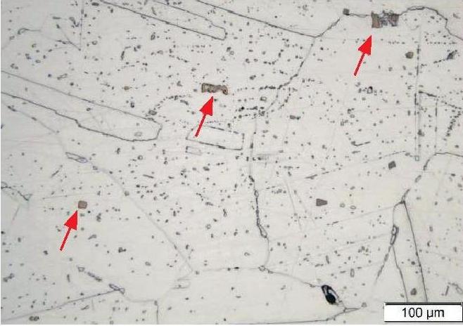
Alloy 800 and its variants are solid solution alloys. The microstructure of these alloys consists of wrought equiaxed austenitic grains with annealing twins, see Fig. 2. Grain boundary and cuboidal orange/pink intragranular precipitates (e.g. Ti(C,N)) are also present in the microstructure.
Damage that occurs in outlet pigtails can be grouped as creep, creep fatigue, environmental attack and relaxation cracking7. The main damage mechanism for pigtails covered in design codes and standards such as API 5308 is creep. Classical creep damage accumulates in a pigtail as a change in diameter from internal pressure (i.e. hoop stress). Using standardised material properties, conservative design temperatures and pressures, a minimum wall thickness can be determined to obtain a nominal design life of 100,000 hours. In-service creep damage from hoop stress can be monitored by measurement of diametral expansion of the pigtail tube at nominally the hottest part of the outlet tube, see Fig. 3. An example of diametral expansion of pigtails due to creep was presented by M. J. Smillie et al9. For a case study presented, diametral expansions of up to 13% were measured on the pup-pieces welded to the end of the main pigtail tubes after seven years of service, whereas the pigtail tubes had significantly lower diametral expansions (e.g. 1.5% compared to 13% for the pup-piece expansion). The difference in diametral growth was attributed to a variation in grain size between the different pigtail tube sections examined even though both sections conformed to the specification.
Creep damage in the circumferential direction can also occur in pigtail tubes, where axial stresses are greater than hoop stress. Axial stresses can be from transient thermal stresses experienced during startup/shutdown, bending loads and/or other system loads. Additional factors from fabrication (e.g. ovality) may also contribute to locally higher axial stresses. Creep damage from axial stresses can be difficult to monitor between plant shutdowns and will likely involve on-line monitoring methods.
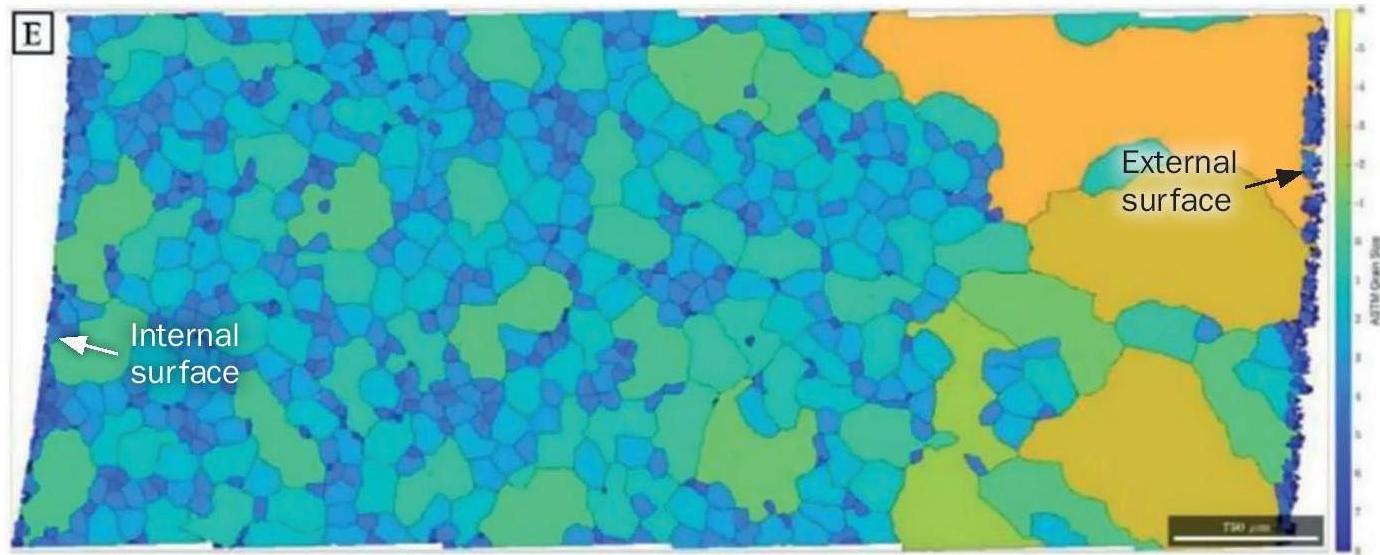
The extent of observed creep damage is affected by the grain size distribution within the pigtail tube’s microstructure. For Alloy 800H and Alloy 800HT, an average grain size of ASTM #5 or coarser is routinely specified. The material’s creep performance is dependent on the grain size distribution to achieve this specification and the relative uniformity of the grains. In particular, coarse-grained regions have better creep strength but have lower creep ductility (i.e. “creep brittle” behaviour) and are unable to deform without voiding and/or cracking. Fine-grained regions have better creep ductility and can deform with less voiding. An example of a mixed grain size distribution in an Alloy 800H/800HT pigtail cross section that meets the ASTM average grain size specification and the corresponding circumferential creep damage observed is shown in Fig. 4. This wide variation in grain size frequently leads to cracking either due to the poor ductility of coarse grains or the concentration of strain into fine grained zones. In addition to the requirement to maintain grain size coarser than ASTM grain size #5, it is recommended that there be a requirement to limit grain size variability.
The variation in grain size is best managed during fabrication. Grain growth response during heat treatment is strongly influenced by the extent of prior cold work. Cold bending will automatically generate variable degrees of cold work and hence variable response to subsequent solution annealing. Fabrication methodologies should be developed to minimise grain size variation.
The presence of creep voids and cracking can also provide a path for nitridation to occur in Alloy 800H and Alloy 800HT pigtails. Nitridation is the formation of nitrogen-rich precipitates and two main forms of nitrides are formed in Alloy 800H and Alloy 800HT materials, see Fig. 5:

- Titanium carbo-nitrides (Ti(C,N)), which are stable precipitates formed during fabrication.
- Aluminium nitrides (AlN), which are typically formed in-service and are generally fine, acicular needle-like precipitates near the external surface. The primary source of nitrogen for in-service pigtail tubes is from the external atmosphere.
The formation of nitride-rich acicular precipitates in-service have been observed around creep cracks and have contributed to pigtail failures7,9,10. Nitridation can reduce ductility and cause embrittlement, although it is acknowledged that published literature validating the effect of in-service nitridation on mechanical and creep properties of Alloy 800H and 800HT is very limited. The rate of formation is a function of the exposure of the pigtail material to air at elevated temperatures. An initial model of the kinetics that enable nitridation to occur in-service for Alloy 800H has been provided by Young et al11.
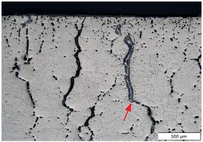
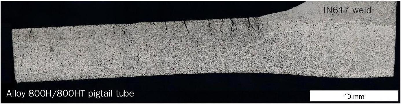
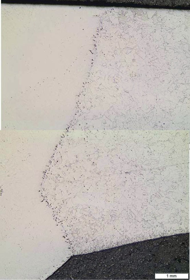
Stress relaxation cracking can occur in Alloy 800H and Alloy 800HT at temperatures between 500°C and 750°C due to grain boundary strain7. This is generally associated with thick-walled components but can also occur in pigtails. This damage is observed as an intergranular crack morphology with a Fe-Ni rich layer sandwiched between chromium/oxide layers (see Fig. 6). Susceptibility to stress relaxation cracking is also increased for outlet pigtail tubes due to the use of Inconel 617 weld filler material. This filler material has relatively better creep properties than Alloy 800H/ Alloy 800HT and therefore result in a mismatch in material performance as observed by a band of creep voids near the weld fusion line in the parent material (see Fig. 7). The risk of stress relaxation cracking can be reduced by using a matching filler material. In addition, procurement of material in a thermally stabilised condition and heat treatment and stress relieving/post-weld heat treatment of welds and cold-worked sections can further reduce risk. For Alloy 800H, the risk of in-service cracking can be further reduced by using a base metal and weld filler material with a combined aluminium and titanium content less than 0.7%.
Manifolds and bull-tees
By far the most common material of construction for steam reformer outlet manifolds and bull-tees is CT15C as described in ASME SA-351/SA-351M12. (SA-351/351M is identical to ASTM specification A351/A351M). It is marketed by a range of suppliers typically using their own proprietary trade designations. This alloy was developed as a cast version of Alloy 800H/ Alloy 800HT and followed catalyst tube developments in being further strengthened by the addition of niobium.
The material is often considered to be a cast version of Alloy 800 and its variants based on its similarity in chemical composition. The adoption of a cast variant saw the use of similar levels of the prime alloying elements, chromium and nickel. Titanium and aluminium were not used in the cast variant. However, in parallel with the development of spun cast reformer tube alloys involving alloying with small amounts of niobium, CT15C similarly was alloyed with approximately 1% of niobium to improve creep properties by encouraging the formation of a fine distribution of niobium carbide particles. The similarities in the compositions of CT15C and Alloy 800HT, as listed in Table 2, are obvious.

Given this improvement in strength and the lower cost of manufacture of the cast material, the benefits of CT15C are clear. This alloy however is not without its problems. Even after relatively short periods in service, routine inspection at scheduled plant outages frequently leads to the discovery of cracking at the weldments connecting the main manifold arms to the bull-tee (see Fig. 9).

Fig. 9 shows a typical bull-tee, and the cracking that may occur. Such cracking has been attributed to bending of the manifold arms relative to the bull-tee13,15. Under such circumstances, the weldments act as a fulcrum point concentrating bending loads at the bull-tee to manifold arm welds. The external bending loads leading to this damage are due to thermal movement of the system caused by both start up and shut down cycles and day to day temperature variations.
This cracking has led to a need to ensure fitness for service or repair. Both of these options are potentially problematic. Fitness for service using codes such as API 5793 requires knowledge of material properties including creep strength, creep crack growth rate and fracture toughness. These data are not readily available for alloy CT15C. Furthermore, experience has shown that ex-service material properties of CT15C may vary significantly from those provided to enable initial design. Fig. 10 shows creep and toughness data obtained following laboratory testing of ex-service manifold material from an ammonia plant that had operated at 760°C. Testing of this material revealed that the creep properties had degraded significantly and the material toughness was extremely low14. Subsequent experience has shown that the material properties shown in Fig. 10 were at the extreme low end of the range, highlighting the uncertainty associated with selecting data for use in fitness for service assessments.

Repair of cracking has shown itself to be equally problematic. Information regarding repair of manifolds is available in API 942-A16. The difficulty lies in the low temperature toughness experienced in ex-service CT15C (Fig. 10) with Charpy impact energies below 10 joules. This has led to serious welding problems. Repair welds typically result in further cracking. The data in Fig. 10 shows that some toughness can be restored by solution annealing, which demonstrates that solution annealing can restore weldability. This is not trivial requiring temperatures in excess of 1,100°C.
Given the significant impact of G-phase in modifying toughness and possibly creep properties by the absorption of niobium and the resulting uncertainty around the resulting material properties, it is suggested that alloying with niobium could be usefully avoided. A niobium-free alloy would in principle at least, not embrittle in service due to G-phase. Alloying with niobium has become standard due to the improvement it offers in creep strength as measured on as-cast material. Manifolds are not restricted to a particular thickness and adequate strength while using a niobium free alloy could be obtained by design. It is significant that failure due to pressure generated creep damage is not unknown but is very rare compared to cracking at bull-tee to manifold welds. Creep data for a niobium-free material has not been found. Nor has information relating to embrittlement processes in such an alloy. Nonetheless, it is considered that the improvement in embrittlement resistance and the variability of ex-service properties may offset the reduction of initial creep strength.
The choice of weld consumable may also affect the performance of these welds. A description of the weld consumables that are used in manifold welds is provided in API Technical Report 942-A16. Inconel 82 has been used extensively in the past. This weld metal has relatively low creep strength and creep failures within the weld metal have seen a migration to the high strength alloys such as 617. Inconel 617 has significantly higher creep strength than the parent CT15C material. The consequence of this appears to be relaxation of weld residual stress concentrated into a narrow zone of parent material adjacent to the weld fusion line. Inconel 617 has the potential to lead to a form of stress relaxation cracking that will exacerbate damage from any bending loads caused by thermal movement of the manifold. This damage is also noted for outlet pigtail joints, as described above. While the objective of using a high strength weld metal would appear to have merit, it is considered more beneficial to use a weld consumable of matching strength to the parent material thereby more evenly distributing welding residual stress.
Discussion
The choice of material of fabrication for both pigtails and manifolds has become firmly entrenched. In the case of pigtails, Alloy 800H and/or 800HT and in the case of manifolds and bull-tees CT15C and its proprietary variants are dominant choices of material. Both alloys have performed well in their respective roles but each has its own unique problems.
In the case of Alloy 800H/Alloy 800HT and its application in outlet pigtails, the aluminium and titanium content has led to long term nitridation damage, ductility drop issues and consequently an increased risk of stress relaxation cracking. Given the spurious origin of these alloying elements in Alloy 800 and its subsequent variants, alternative alloys are considered worthy of consideration. This includes Alloy 330, which is effectively Alloy 800 without the aluminium and titanium additions and hence may avoid some of the deleterious aging characteristics. It is normally used for high temperature corrosion resistance. However, its creep properties without the benefit of grain size control are similar to those of the basic Alloy 800 (Fig. 11)5. If similarly processed to generate a coarse grain size, similar or superior creep properties are likely to be obtained.

Control of grain size in Alloy 800H and 800HT is of prime importance in order to obtain the expected properties. This is normally managed by specifying grain size to ASTM grain size #5 or coarser. This limitation has been found to be oversimplified given that grain size variation within this range can lead to low ductility cracking issues. This grain size variability is mainly caused by fabrication methods since the grain growth during heat treatment is strongly affected by the degree of cold work prior to the solution anneal heat treatment. It is considered that fabrication approaches need to be modified to control this affect. An example would be to hot bend pigtails, in addition to quality checks of the product during fabrication.
In the case of manifold materials, the use of CT15C as the material of choice has merit due to its good creep performance. However, its propensity to aging leading to variable material properties and embrittlement has led to problems. The prime reason for this is believed to be the formation of G-phase in service. It absorbs niobium removing it from its prime role of improving creep strength and leads to low temperature embrittlement leading to weld repair difficulties. Eliminating the source of G-phase i.e. niobium would likely require compensation by design to increase wall thickness but has the potential to at least reduce in service degradation of material properties.
Choice of weld metal is also important. Inconel 617 has found favour to counteract creep failures encountered in weaker weld metal. It is suggested however that stronger is not necessarily better and results in high residual stress and consequential relaxation cracking in the adjacent parent metal. It is considered that a matching weld metal is more likely to provide long time reliable performance.
The materials issues highlighted here have their roots in attempts to improve high temperature performance by alloying i.e., aluminium and titanium in Alloy 800(H/HT) and niobium in alloy CT15C. These alloying additions however result in long term instability of material properties. In selecting alloys for stability, unless absolutely necessary to maximise strength, keeping the material as simple as possible would appear to have merit.
References