Nitrogen+Syngas 392 Nov-Dec 2024
30 November 2024
Introducing ammonia flow-induced corrosion
CORROSION CONTROL
Introducing ammonia flow-induced corrosion
In recent years, extensive and severe internal attack has been observed of carbon steel equipment and lines in aqua ammonia service at several Yara manufacturing sites across the globe. In all cases, the damage has a distinct flow-accelerated corrosion (FAC) signature which challenges the current understanding of FAC. All features typically observed for this kind of damage mechanism, that seem to be specific to the NH3 recovery section of ammonia plant, are reported. Upgrading the material of construction for this unit, will solve this failure mode, but a leak would potentially generate health and safety problem for the release of ammonia.
Extensive, severe internal corrosion has been observed in carbon/lowalloy steel equipment and piping in aqua ammonia service at several Yara manufacturing sites around the world in recent years. Whereas this itself is remarkable in the sense that such steels are widely used as construction materials for ammonia1 it has come as an even greater surprise that in all cases the damage had a distinct flow-accelerated corrosion (FAC) like signature.
Historically, FAC used to be referred to as erosion-corrosion2 . It is one of the most important and dangerous failure modes in water-steam cycles.
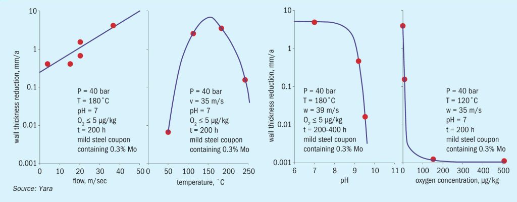
FAC is an electrochemical-mechanical damage mechanism that manifests itself both in single phase and two-phase forms. In addition to steel grade/composition and geometry in general there are a number of system parameters known to play a key role in “conventional FAC”. These system parameters and their effects are illustrated in Fig. 1.
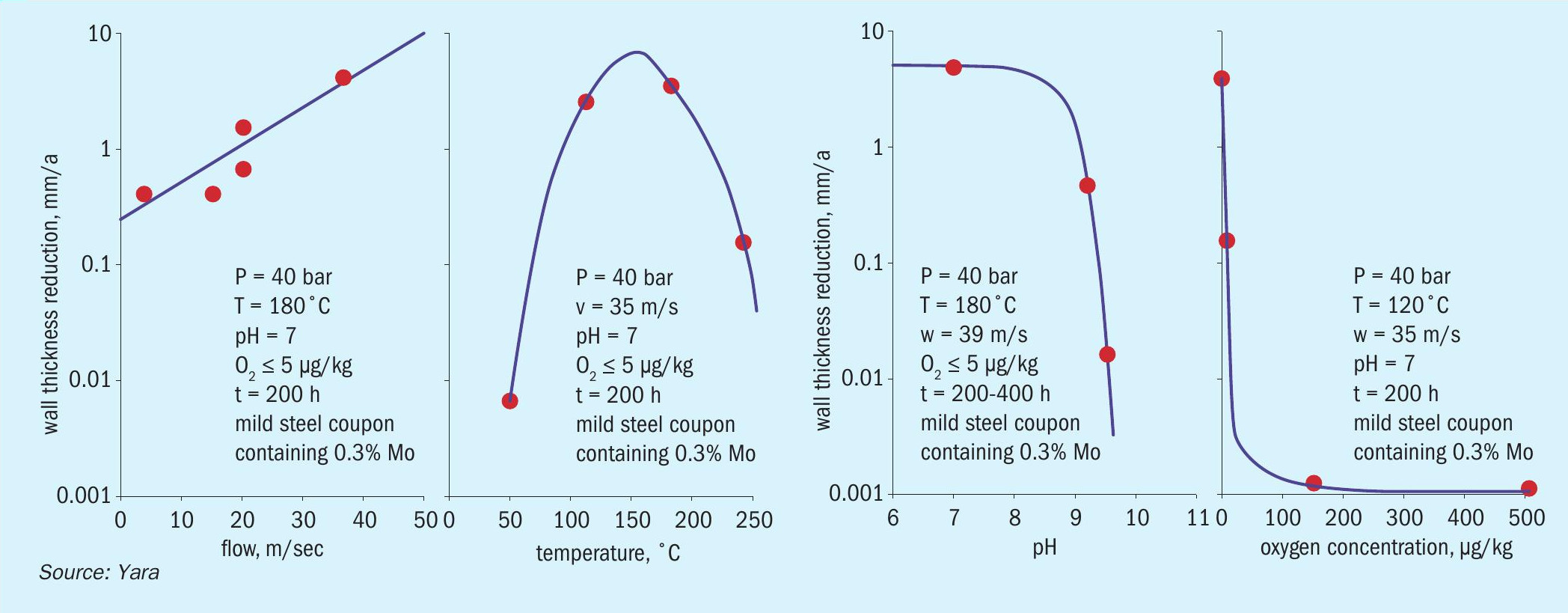
It should be noted that nowadays a trace amount of molecular oxygen is considered beneficial to combat FAC with ferrous metallurgy. For a comprehensive overview of the current under-standing of FAC in steam systems the reader is referred to reference 3.
In the authors’ view, the damage that has occurred in aqua ammonia loops in Yara plants suggests a potential FAC knowledge gap, especially with regard to pH. Indeed, the pH of ammonia-water mixtures containing up to say 25% ammonia is obviously far above the value of 9.8 (at 25°C) which is generally considered sufficient to arrest FAC in a steam system.
Extrapolation of the pH graph in Fig. 1 leads to the interpretation shown in Fig. 2. Unfortunately, at present insufficient reliable data points are available to establish the actual location of the curve on the far right side.
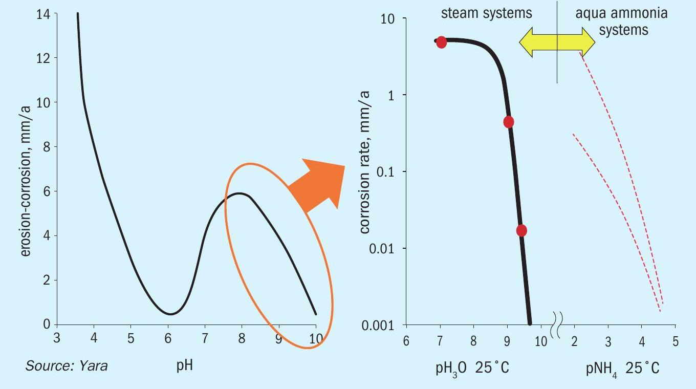
Interestingly, the worst damage found in aqua ammonia systems, just like with “conventional FAC”, occurs at a temperature of ~150°C (300°F) – see temperature graph of Fig. 1. Following extensive discussions with specialists, notably Dr. Barry Dooley of Structural Integrity Associates, Yara hereby introduces ammonia flow-induced corrosion (AFIC) to describe the FAC-like damage encountered in aqua ammonia systems. In this way, any confusion with FAC as defined in the context of the power industry is avoided.
Damage locations
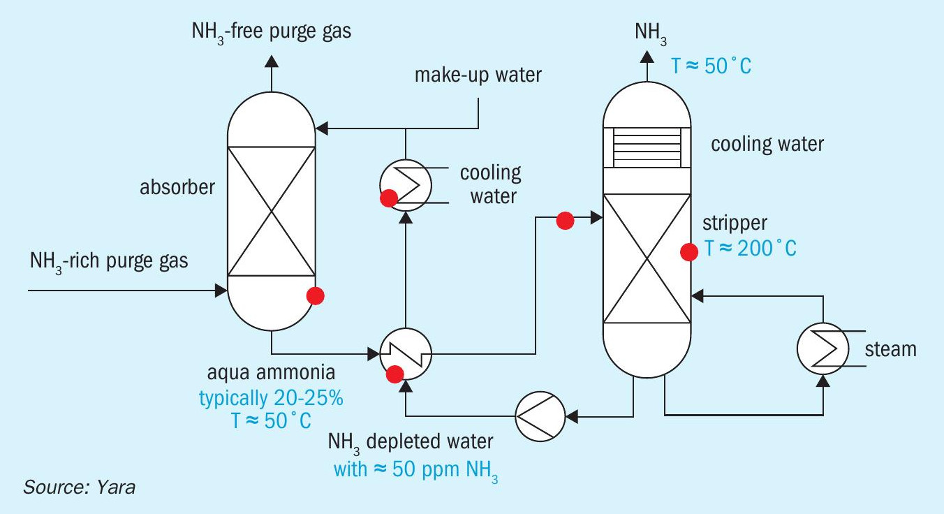
Fig. 3 shows the areas in the ammonia stripping/recovery section of a typical ammonia plant flowsheet where AFIC has been observed in Yara:
- bottom of absorber – with two-phase flow and high turbulence;
- nozzles on shell side of heat exchangers and first tube rows – due to flashing or fluid impingement;
- inlet nozzle and shell of stripper on opposite side – because of high turbulence and impact.
- Experience has shown that a double pipe design heat exchanger is especially susceptible to AFIC.
Case description
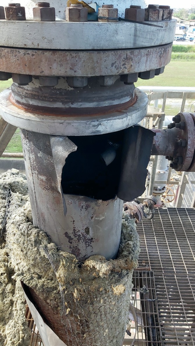
On April 28th, 2022 a serious incident occurred at a Yara manufacturing site. This involved loss of containment (LoC) from the ammonia stripper, fortunately without any harm to people present in the plant at that time.
The liquid distributor was found to be completely dislodged from the column through the rupture opening arising from the incident. It was located some 12 m (40 ft) away from the stripper. The event could potentially have caused severe physical injury to personnel in the vicinity of the failed equipment. A release of ammonia to the environment also occurred in the period until the unit was stopped.
Plant operations responded to the event by first identifying the area in which the incident occurred via the distributed control system (DCS) and then promptly shutting the unit down. Investigation into the incident commenced on May 4th, 2022. Given its severity, site management requested a comprehensive root cause analysis (RCA) to identify the main cause(s) of the failure and define possible mitigation actions.
The investigation team consisted of local staff from process, operations, maintenance, and inspection departments. Experts from Yara’s central support team were also involved in the RCA as well as an independent third-party company. The mandate of the team and the goal of the investigation was to:
determine and document the sequence of events, as well as all other information, circumstances, and conditions that were considered to have contributed directly and indirectly to the incident;
- review and comment on emergency response actions and performance;
- deep-dive into technical, organisational, and human aspects of importance to the incident;
- identify non-conformity with respect to regulations and company requirements related to the incident;
- identify preventive actions and recommend corrective actions for the site.
The rupture of the shell of the stripper occurred immediately beneath the middle flange and to the west of the liquid feed nozzle (Fig. 4). At the instant of rupture, the distributor tray (below the nozzle) was propelled outwards, possibly colliding with the internally projected liquid feed line. The liquid feed line (2 in Sch 160 pipe) was found to be significantly thinned and was warped/ twisted consistent with impact from the distributor tray. This led to the decision to remove and replace the line. The removed section was subsequently sent to an independent laboratory for failure analysis on June 1st, 2022. Evidence suggested that the feed line was externally corroded by “FAC”, to such an extent that the line became perforated between the 10 and 12 o’clock positions, just before the elbow.
From the work done by the investigation team it has been concluded that the ammonia stripper is subject to multiple corrosion mechanisms working simultaneously. The two key types of corrosion identified are:
- primary mechanism: carbon/low-alloy steel corrosion in an oxygen-depleted environment;
- secondary mechanism: FAC-like attack.
The primary mechanism has always existed and is dependent on the steel grade applied under the service conditions. A corrosion inhibitor could be used to mitigate it but there is no historic information about this in the aqua ammonia loop of the plant. Interestingly, corrosion inhibitors apparently are widely used in ammonia heat pump systems, including extremely undesirable sodium (di)chromate8,9 . Alternative inhibitor chemistries described are:
- “usual suspects”: silicates, molybdates, borates, etc.;
- rare earth metal salts (REMS), especially cerium nitrate.
- There seems to be no experience with film-forming substances yet.
To gain further insight into the secondary mechanism and to validate the results of the investigation done by the RCA team, an additional failure analysis was contracted to another independent laboratory.
This lab came back with the following statements: “… ammonia-water solutions are not completely inert towards carbon steels, especially at higher temperatures. The corrosion attack is expected to formnon-protective magnetite scales. High flowrates can cause these scales to be continuously removed leading to an accelerated attack. Conventionally, in advanced ammonia absorption systems, a corrosion inhibitor in the form of sodium chromate (Na2CrO4) or sodium dichromate (Na2Cr2O7) is added …to inhibit the working fluid from reacting with the steel … Sodium chromate is effective for operating temperatures up to about 200°C. While uninhibited ammonia-water is not inert towards carbon steels, the corrosion rate is still expected to be limited at current operating temperatures (up to 154°C). This is in accordance with the observations of the plant that the attack mainly occurred at the locations subjected to the highest flowrates”.
The RCA concluded with a review and comparison of the performance of various ammonia recovery strippers across Yara. All of these are made out of carbon/lowalloy steel with (austenitic) stainless steel wetted internal parts (packing, trays etc.). From this study it became clear that they all experienced magnetite (Fe3O4) dissolution and redeposition in the form of black powder. However, the extent of integrity issues is variable across the company, from no wall thickness loss whatsoever to multiple occurrences of significant attack.
In addition to the aforementioned replacement of the feed line the entire bottom section of the damaged stripper will be replaced in austenitic stainless steel during the next turnaround. It goes without saying that the tower condition is strictly monitored through non-destructive testing (NDT) and visual inspections.
Closing remarks
The authors of this article are conscious that the surface of AFIC as a failure mode has merely been scratched. It is evident that a substantial effort will be required to further the understanding of its mechanism. In this regard, it is hoped that this article not only raises awareness in the ammonia industry but also generates interest in the academic world.
AFIC should be systematically included in corrosion studies of ammonia plants, with appropriate risk ranking and, where required, modification of equipment and piping inspection plans.
Acknowledgments
The authors wish to thank the management of Yara for permission to publish this paper. The computational work on concentrated NH3 -H2O systems by Peter de Moel of Omnisys in the Netherlands is gratefully acknowledged.
References and bibliography