Nitrogen+Syngas 392 Nov-Dec 2024

30 November 2024
Revamp activities in urea plants
UREA REVAMPING
Revamp activities in urea plants
Urea revamp activities are performed to achieve improvements of the urea plant. Besides the typical capacity increase there are many options to reduce operation costs, increase plant availability or reduce environmental impact. In this article Marc Wieschalla of thyssenkrupp Uhde GmbH provides an overview of some of the options from an EPC contractor point of view.
The meaning of revamp is to change something, to make or to design something differently, to improve it.
Applied to urea plants the improvement can have very different objectives as listed below:
- increasing production capacity;
- utilisation of CO2 sources or surplus ammonia;
- reducing operation costs, e.g., by reducing energy consumption;
- improving the environmental impact, e.g., by reducing emissions;
- increasing plant availability and reliability, e.g., through the use of improved construction materials or state-of-theart technologies;
- production of additional urea products such as AdBlue® or melamine;
- improving operating comfort, e.g., by modernising the control system.
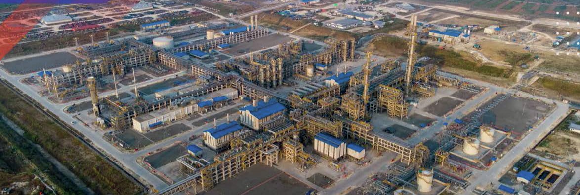
The most common goal is to increase production capacity because the additional output pays off. thyssenkrupp Uhde GmbH (Uhde) has more than 65 years of experience in engineering, supply of equipment and commissioning of urea plants with more than 120 plants built worldwide. For urea synthesis, Uhde works with the license of Stamicarbon, optimally combining it with the license of tkFT being preferred for the granulation. Thus, Uhde also offers revamp activities for both processes and additionally for plants using different technology, which can be revamped based on Stamicarbon and tkFT process design packages.
Revamping for capacity increase
The melt plant
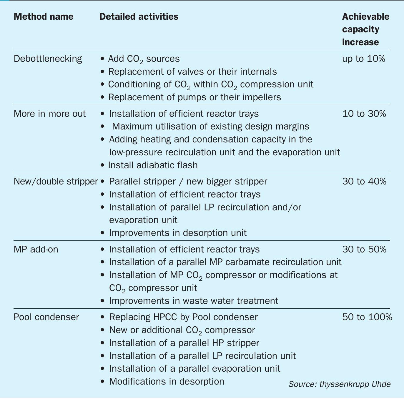
For the melt plant, there are five basic concepts for increasing the capacity of a plant. The first is debottlenecking, which can achieve a small increase in capacity of up to 10%. As a rule, the equipment stays untouched and only control valves, pipes and pump impellers are changed or replaced. The bottlenecks can be identified during a plant visit by observing DCS data, checking equipment data sheets and interviewing operators. Based on a detailed recalculation and specification of the identified bottlenecks, the required measures can be detailed. After implementation, the new achievable capacity can be tested and additional bottlenecks identified, if any. Other revamp methods as shown in Table 1 can achieve higher capacity increases of up to 100% of the original capacity. In these cases, the involvement of the licensor is a must and the replacement, or modifications of static equipment is required.
The urea granulation plant
The activities involved in revamping the granulation plant can be divided into two types:
- Smaller revamps can achieve capacity increases of up to 15% of the original capacity. Intensive work requiring structural adjustments and welding to equipment is avoided, i.e., the granulator casing and fluid bed coolers are left untouched, as is the material handling circuit. Instead, the new nozzles can be installed in the granulator to provide more urea melt feed. With the additional melt feed, there is more crystallisation heat released to be removed. As a result, the cooling capacity will need to be increased if there is no spare cooling capacity. More cooling can also be achieved by adding additional coolers, e.g., a bulk flow cooler, or by increasing the cooling capacity, e.g., by chilling the water circuit of the bulk flow cooler or by adding chillers in the fluidisation air supply.
- Larger revamps are required for higher capacity increases of up to 45% of the original capacity. It requires modifications to the granulator. The existing cooling zones are used as new spray zones by installing additional nozzles and extending the number of melt headers. A new cooling zone is required. This is usually achieved by extending the granulator. Alternatively, a second granulator can be installed. The cooling section must also be enlarged by extending the fluid bed coolers or installing a bulk flow cooler. To ensure sufficient cooling, the fans must convey more air. This can be achieved by installing new atomisation and fluidisation air fans. If the requested capacity increase is on the lower side and sufficient margins can be used, changing the impellers and installing new pads inside the scrubbers with very low pressure drop may be sufficient to avoid the installation of new fans. Typically, however, emissions need to be reduced as well when performing a revamp and, with additional ammonia abatement, pressure drop increases. Consequently, new fans are often required. In order to reduce investment cost a booster fan can be installed. The existing fan is then operated at a higher pressure and less flow as originally designed and the booster fan delivers the resulting difference in flow. Material handling equipment must be adapted to handle the higher granules flow. Spare capacity can be used to keep investment costs low.
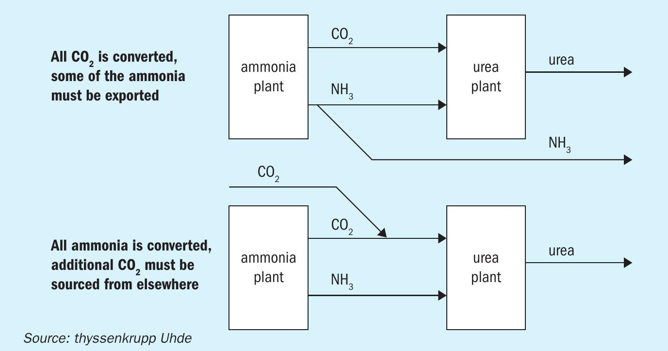
An important question for a capacity increase is where the required feedstock is coming from. This question is particularly important for the CO2. In a conventional, natural gas based, ammonia and urea plant complex a surplus amount of ammonia is produced, that cannot be consumed for urea production. There is a lack of CO2 to form urea. This is due to the fact that the production rates of ammonia and CO2 are normally not independent from each other. In an idealised process where ammonia is produced from pure methane (CH4 ), air and water, the ratio of the products CO2 and ammonia is 1.14 t/t. In a real process, this ratio can be lower or higher, depending for example on the natural gas composition and the losses in the process.
In contrast to that, the urea plant consumes CO2 and ammonia in a higher ratio of approx. 1.29 t/t (0.73 t CO2 / t urea and 0.57 t NH3 / t urea). Hence there is a lack of about 0.15 t CO2 per t of ammonia if all of the ammonia produced is utilised for urea production.
Exceptions are balanced ammonia plants which are rare. In all plants the CO2 source in ammonia urea plant complexes is the CO2 removal unit of the ammonia plant which removes the CO2 from the synthesis gas of the reformer downstream of the CO shift.
There are several ways to generate the additional CO2 required for the capacity increase. One of these is to increase production in the CO2 removal unit of the ammonia plant. Another option is to use a separate unit to collect CO2 from other CO2 containing streams such as flue gases. The third option is to import CO2 from outside the battery limits, if feasible, e.g., from nearby power plants or cement plants.
CO2 removal unit in ammonia plant
The CO2 for urea production is normally obtained by separation from synthesis gas in the CO2 removal unit. The amount of CO2 can be increased by passing more synthesis gas through this unit. Downstream of the CO2 removal unit, the excess synthesis gas not needed for ammonia production is withdrawn and fed to the reformer to be used as fuel gas. This system increases the plant’s fuel gas consumption and results in a higher throughput and consequently higher outputs in the front-end units for desulphurisation, reforming, waste heat recovery, CO shift and CO2 removal. On the other hand, recycling part of the synthesis gas to the reformer as fuel leads to a reduction in the natural gas used as fuel. However, overall this increases natural gas consumption. The energy of the additional amount of natural gas is not lost because the higher throughput of the synthesis gas generation units increases steam production. A benefit occurs if this steam can be used e.g., in surrounding plants.
If the additional amount of CO2 required is small and there is still design margin in the front-end units, the required modifications and cost are minor, as only one let-down for a small synthesis stream to the reformer’s fuel gas system is required. If higher CO2 quantities are required, one of the following options can be considered.
CO2 removal from flue gas
The flue gas from the reformer and the package boiler contains high amounts of CO2 , making them a potential source of CO2 for urea production. There are several technologies to recover CO2 from the flue gas streams. The processes applied to flue gas are based on the same principle of absorption and desorption as the CO2 removal process from the ammonia plants’ synthesis gas. The recovered CO2 is of good quality (no hydrogen content) and can be mixed with the existing CO2 stream upstream of the CO2 compressor. Amines are often used as solvents. These processes are also used for separation of CO2 from fossil power plants and blue ammonia plants for subsequent sequestration.
Uhde has developed a CO2 removal process, shown in Fig. 2, to purify such CO2 streams for use in urea plants. The advantage is that no additional scrubbing agent such as amine solutions are needed, instead ammonia, which is present in the complex, is used. This process requires a high pressure of approx. 150 bar which perfectly meets the requirements of the urea plants for CO2 injection. This process avoids the need to change the CO2 compressor. If the capacity of the ammonia plant is also increased this unit can be dimensioned to also consume the additional reformer exhaust gases so that it is not necessary to replace or change the CO2 removal unit in the ammonia plant. With the help of this unit, a considerable increase in plant capacity can be achieved while at the same time increasing energy efficiency. Critical elements such as the CO2 compressor can remain untouched.
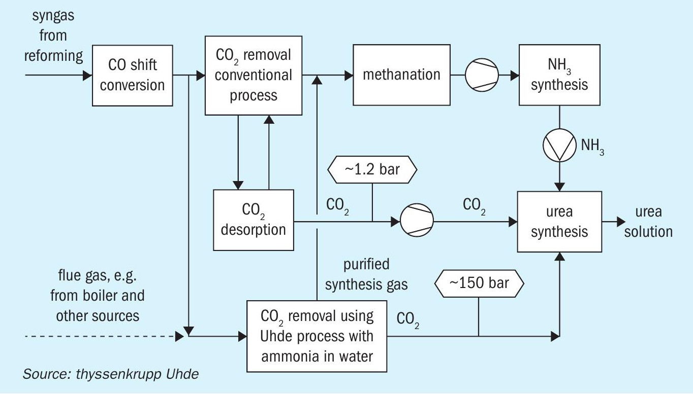
A CO2 removal unit is a separate and additional unit that is connected to the flue gas outlet of the reformer or boiler, but does not have many other connections to the rest of the plant. Therefore, the installation of such a unit as part of a revamp can be done quite easily.
On the other hand, the investment costs are relatively high and there are operating costs for solvent regeneration, steam and electricity for pumps and flue gas fans. In addition, the solvent losses must be constantly compensated for by adding fresh chemicals.
CO2 from direct air capture
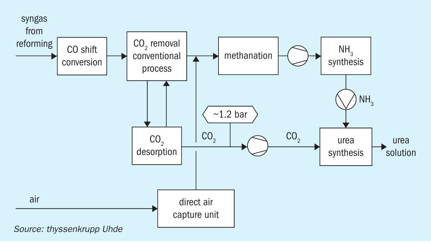
Another emerging option for supplying CO2 is the direct air capture process (see Fig. 3). The CO2 is removed from air and added to the CO2 supply to the urea plant, e.g., on the suction side of the CO2 compressor. The available processes are currently in the upscaling phase and the available systems only allow small increases in production of approx. 1 %, while the investment costs are still high. In the long term, direct air capture will offer the possibility of producing green urea, which only releases the amount of CO2 during dissociation that was previously captured from the air. The second feedstock must of course be green ammonia.
Emission reduction
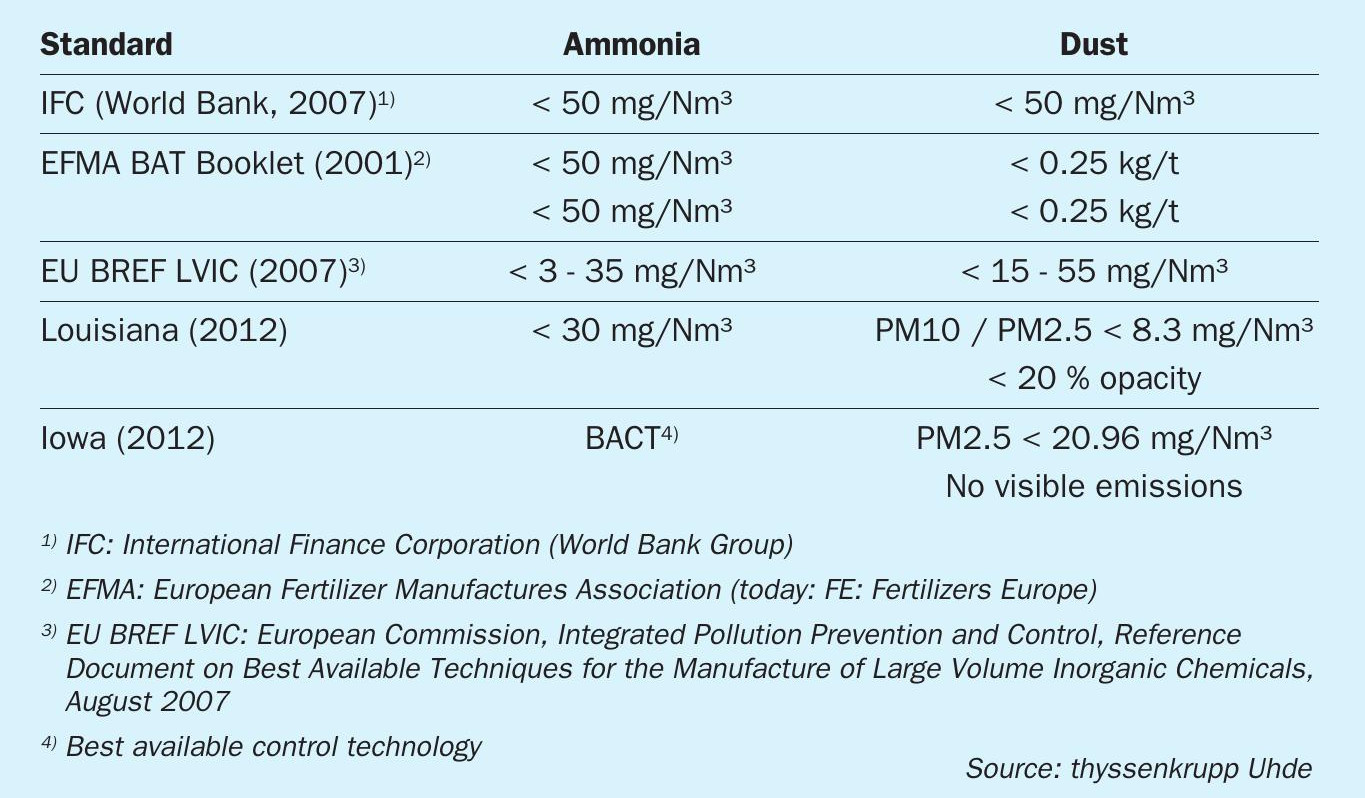
In recent decades, ammonia and urea dust emissions in urea plants and their reduction have become a challenge. The focus has been on continuous emissions, but emissions resulting from upset operation of the plant as well as accidental emissions have also come into focus. As a result, laws and regulations as well as local conditions, customer requirements and international standards have become more stringent. Older plants often do not comply with the new regulations. Table 2 shows some of the current requirements of the various international and local standards.
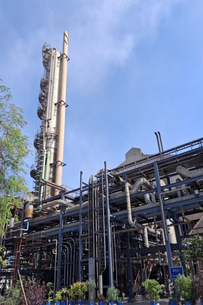
In a urea plant that produces granules, there are usually three emission points: Although the emissions from the two absorbers in the melt plant (see Fig. 4) only amount to approx. 4 to 6 kg/h of ammonia, the concentration limits are far exceeded due to a very low total throughput. The emissions from the granulation stack (see Fig. 5) amount to approx. 80 to 90 kg/h of ammonia, but the large volume of air dilutes the concentration to approx. 100 mg/Nm3 .
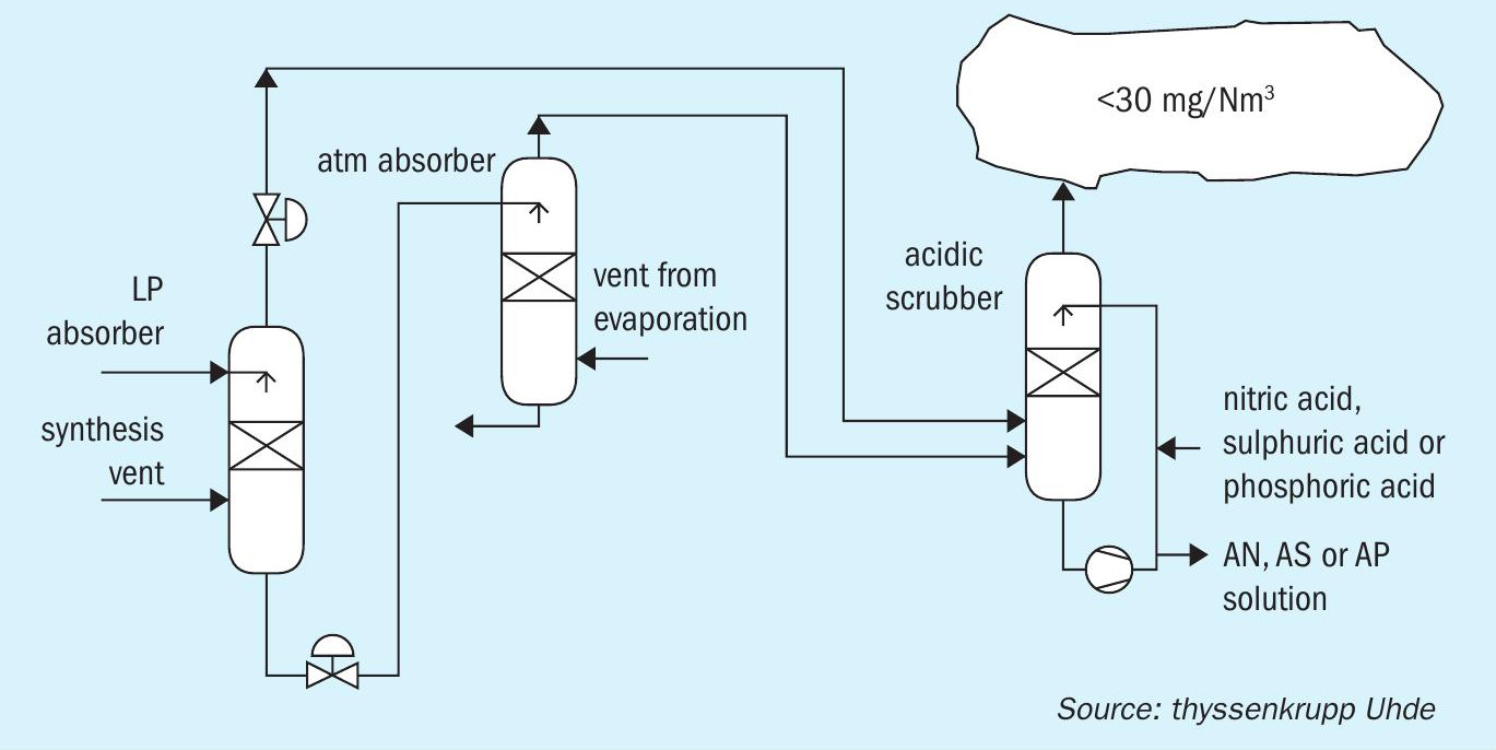
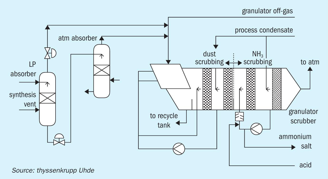
State-of-the-art scrubbers for ammonia and dust reduction with water and acid solutions (see Figs 4 and 5) now meet even the strictest regulations. In existing plants, these technologies can be added by replacing the inner pads or trays of the existing scrubber, installing a dedicated acidic scrubber or replacing the scrubber with a new combined dust and ammonia scrubber. The decision is made based on the actual emissions achieved with the old scrubber system, the total new pressure drop and the required changes to the air system, e.g., the exhaust fan. Due to the lower pressure drop of the new scrubber pads, there are cases without the need to replace the fan. Either an increased impeller is sufficient, or a small booster fan can be installed.
Uhde has built new plants in the US with scubbing technologies complying with the local standards shown in Table 1. The scrubbers achieved ammonia emissions of 11.1 mg/Nm³ (EPA 9 method) and dust emissions of 0.86 mg/ Nm³ (EPA 5 method).
Since acidic scrubbers are part of many new build plants, their use is well known. Three types of acid have proven themselves for ammonia reduction:
- nitric acid
- sulphuric acid
- phosphoric acid
On contact with the gaseous ammonia, ammonia salts are formed which leave the scrubber either as an ammonium nitrate solution, ammonium sulphate solution or ammonium phosphate solution. The ammonium nitrate solution can be used in a UAN or ammonium nitrate plant. If sulphuric acid is chosen, the solution can be concentrated and sent to the granulator together with the fresh melt from the melt plant. When granulated together with the fresh urea the sulphur content is smaller (0.1 wt-%) but nitrogen is still high, more than 46 wt-% (fertilizer grade). Due to the corrosivity of the free sulphuric acid, the granulator material of construction must be 316/316L, but most plants are built of 304. Alternatively, a crystalliser can process the resulting solution to produce ammonium sulphate fertilizer. If phosphoric acid is used, MAP or DAP can be produced from the solution. The choice of acid is therefore mainly influenced by three factors:
- availability of acid;
- processability of the resulting ammonium salt solution;
- the construction material of the granulation plant.
Improving plant availability
In addition to overhauling systems that have reached end of life, replacing certain equipment with overall new concepts can increase plant availability. One example is the use of a so-called self-regulating pump as a melt pump to supply the granulator. The main feature of this pump is that it can be operated with almost zero suction head (NPSH = 0 m). Therefore, it can be installed close below the second stage evaporator in the melting plant.
The fact that the self-regulating pump does not require a NPSH leads to a couple of advantages.
Due to the close distance to the evaporator, the pipe length on the suction side is shortest. Because the pump can be installed at a level higher than ground level, there is no need to route the pipe up and down, instead it can be directly connected to the granulators melt header at the same level. This also keeps the pipe length short. The pump takes the flow as it gets it. This feature prevents level build up on the suction side. All this leads to low residence times of the hot urea melt resulting in minimised biuret formation.
A further advantage of the self-regulating characteristic and the fact that no NPSH is required is that no level control or even pump protection is necessary. This avoids shutdowns of the downstream plant which would otherwise be triggered by a low suction level, e.g., specifically plants with a granulation, and UAN and/or a DEF unit in which the solution feed to the evaporation is varied from time to time.
In order to place the pump in the centre of the structure and achieve the required pump characteristic, the connecting pipes must be designed according to the requirements of the pump. Special vent lines and height requirements must be taken into account. Uhde holds the patent rights to apply this pump in a urea synthesis plant.
How to approach a revamp
Fig. 6 shows an ideal overview of how a revamp can be approached. Basically, there are four steps. It starts with a study which results in the process concept and a first idea of the cost is derived. If a more precise cost estimate is required, the EP/C contractor must already be involved at this phase. Detailed concepts can then be considered. Examples of questions to be clarified are: where do the required utilities come from and how can the higher quantities be achieved at the source? Is there enough space available to place new structures? How can the revamp be carried out to minimise downtime?
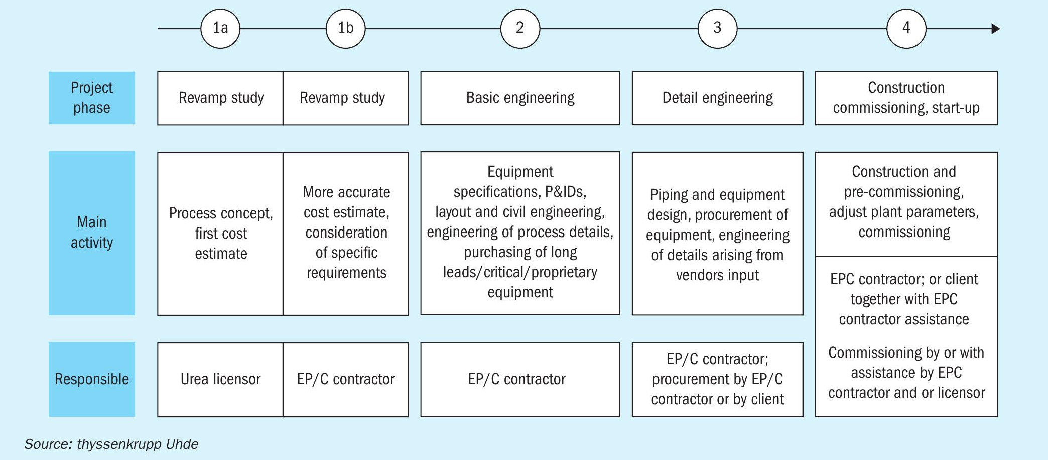
In the second phase the basic engineering is carried out on the basis of the licensor’s process design package (PDP) and concepts of the EPC contractor. In this phase the first equipment is purchased (proprietary equipment, critical equipment and equipment with long lead times). In the third phase the detail engineering is performed, and all remaining equipment is purchased. This phase is usually performed by the EP/C contractor. Agreed parts of the phase, e.g. the purchasing, can also be done by the client. It ends with the construction and commissioning of the new parts of the plant. While construction is usually carried out by the contractor or with the contractor’s support, there are more options for commissioning. If the customer is very experienced, they may only need advisory services. If the customer is not so experienced, Uhde also offers complete commissioning services together with the support of the licensor.
Input of the contractor
It is often assumed that everything is fixed when the process concept is selected and the licensor’s process design package has been supplied. However, an experienced contractor can contribute valuable detailed concepts for adapting the process design package, as shown in the following two examples.
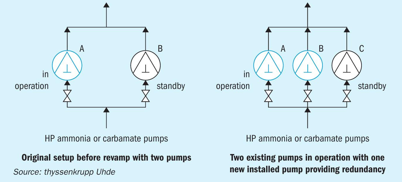
A suitable spare parts philosophy must be defined by the contractor. A perfect example in urea plants is the spare parts philosophy for the high-pressure pumps, which are quite expensive. It is important to work with the customer to find the best spare philosophy that is suitable for their opex and capex needs. However, the information obtained as part of the PDP is sufficient to provide equipment specifications for different pump capacities required for the various possible spare part concepts. This enables the contractor to develop the solutions. The left side of Fig. 7 below shows a typical arrangement of the high-pressure pumps in the urea melt plant. The following three philosophies are possible:
- Keep existing pumps without modification. Both pumps must be in operation to achieve the required flow after the revamp. No spare pump is available. This is the option with the lowest capex costs but has high opex.
- Replace the two existing pumps with new ones, each capable of handling the increased flow after revamp. Only one pump will be in operation and the other one in standby, providing redundancy. This solution has the highest capex cost, but the lowest opex cost, as each pump is designed for the new operating point.
- Install a third pump alongside the existing pumps that can handle the entire flow during operation and keeping the existing two pumps has the following advantages. Either the new pump is in operation, or the two old pumps are in parallel, thus achieving redundancy. As only one new pump needs to be ordered, this is the solution with the lowest capex costs to achieve redundancy. When the newly installed pump is in operation, this solution also has low opex, while higher operating costs only occur during the times when the two existing pumps are in operation. However, this solution requires an available area to install the additional pump.
Another example where the contractor can contribute is in the detail of the cooling water loop. In a so-called MP add-on, an additional section is added to the existing plant, which is operated at medium pressure of approx. 20 bar. In this section, unreacted carbamate is removed, which cannot be converted to urea in the high-pressure synthesis unit after capacity increase. As the removed carbamate is gaseous and needs to be recycled back to the HP synthesis, it is condensed in the MP carbamate condenser, then pumped. The heat of condensation is removed by cooling water. To prevent the carbamate from crystallising, the cooling water is controlled to 80°C. The outlet temperature of the cooling water is around 90°C. In this specific example, the customer stated that they had noticed increased fouling in the cooling water loop of the high-pressure scrubber and the low-pressure scrubber that were installed in the originally built melt plant. These two scrubbers and their cooling water loops are comparable to the loop of the new MP carbamate condenser. Fouling occurred in the plate heat exchanger, which is intended to condition the closed cooling water loop.
As part of the revamp, this design was improved by installing an additional pump as shown in Fig. 8, which generates a secondary circulation around the plate heat exchanger and reduces the inlet temperature to the plate heat exchanger by mixing the hot return water with already tempered water from the outlet of the heat exchanger. Scaling the ratio between two flow rates by scaling the size of the additional pump results in a certain mixing temperature which is reduced to such an extent that the tendency of fouling is significantly reduced.
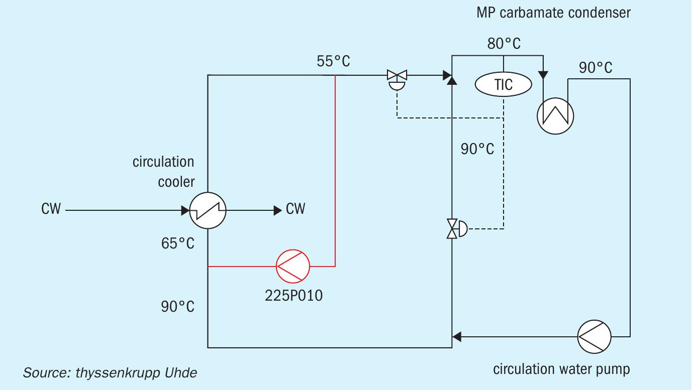
In the specific case of this example, the same modification was made to the cooling water loop of the high-pressure scrubber and the low pressure carbamate condenser. As a result, better performance and higher availability of the entire plant was achieved.
In summary, there are different ways to conduct a revamp for a urea plant. An ideal way is that the licensor provides reliable consumption data for raw materials and utilities in an early phase. Based on this data the contractor can provide further detailed input at an early stage and evaluate the commercial feasibility of the revamp. Based on the reliable emission figures, contractors can check for any change of existing environmental permits, if required, or provide and consider further detail changes. To achieve the best outcome for customers, it is essential that all parties involved work together and provide important information at all phases of the revamp.