Sulphur 417 Mar-Apr 2025
18 March 2025
Preventing regenerator amine carryover
AMINE SYSTEMS
Preventing regenerator amine carryover
Amine is meant to enter near the top of a regenerator and only flow steadily downwards. Several factors exist that can reverse this direction and cause the amine to flow upwards instead, running the risk of entering the sulphur recovery unit. This can have catastrophic consequences and must be avoided at all costs. B. Spooner and M. Sheilan of SGS Amine Experts detail how by correctly interpreting operating data, having proper instrumentation and good chemical analysis, amine carryover can be prevented.
Amine systems are continuous circulating loops, where the amine goes from being loaded up with acid gases to being unloaded. The amine regenerator (also referred to as a still, stripper or reactivator) is designed to do the unloading; it removes H2S and/or CO2 from rich amine, enabling amine to be reused. The acid gases driven from the amine then flow from the regenerator to the downstream processing unit, which is often a sulphur recovery unit (SRU) if there is enough H2S present to warrant one. In low H2S systems, alternative destinations for acid gas can be compressors (for re-injection into the ground), thermal oxidisers or sometimes the gas is simply vented. No matter the destination, amine carryover with the gas is always detrimental and should be completely avoided. Regenerators are typically designed with protection against amine entrainment with the acid gas, but sometimes accidents happen – accidents that can be avoided with proper operation and troubleshooting abilities.
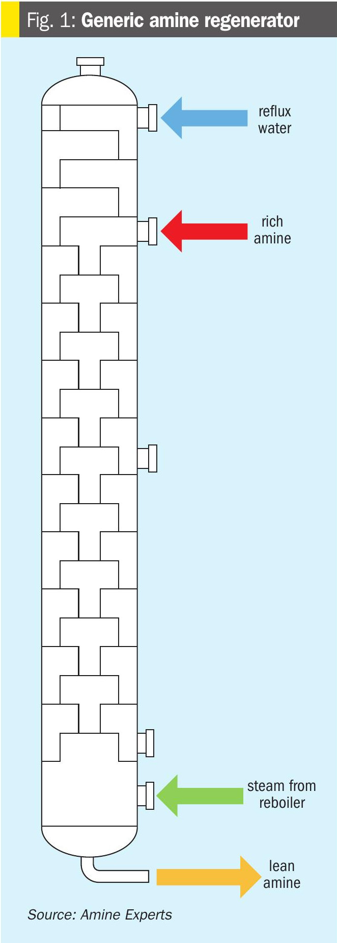
A typical amine regenerator is shown in Fig. 1. Reflux water enters onto the top tray. The rich amine stream enters on usually the 2nd or 3rd tray from the top, but in some locations, there can be as many as four reflux trays. There is a vapour return line from the reboiler entering in the lower part of the column, and the regenerated (lean) amine exits from the bottom. There are many variations to these designs; variations that may affect amine carryover will be discussed in this article.
Regeneration fundamentals
Proper understanding of how regenerators operate helps considerably with preventing amine carryover. The following aspects will be used through this report.
When amine enters the regenerator, it should immediately contact steam and be heated. The increase in amine temperature inside the regenerator is referred to as sensible heat (the energy required to raise the temperature of a substance; measurable with a thermometer). The amount of sensible heat required is a function of the amine flow rate and temperature; the lower the flow and higher the regenerator feed temperature, the less sensible heat duty is required inside the tower. Most of the sensible heating should be done in the first few trays (or one metre of packing), after which point the amine should be only a few degrees from its boiling point.
If the reboiler does not produce enough steam, and there is inadequate sensible heat available when the rich amine enters the tower, the amine simply does not heat up. It flows down the regenerator at the same temperature it entered until closer to the bottom where it then encounters the small amount of steam from the reboiler. Because amine does not regenerate until it is heated, this “collapsed temperature profile” means most of the acid gases and, potentially, foam-promoting contaminants will be pulled to the bottom of the tower. Acid gases liberated from the amine will enter the vapour space and attack bare, non-amine wetted metal (the most common areas of attack are just below the bottom tray or packing support, or in the vapour space of a kettle-type reboiler and steam-return line).
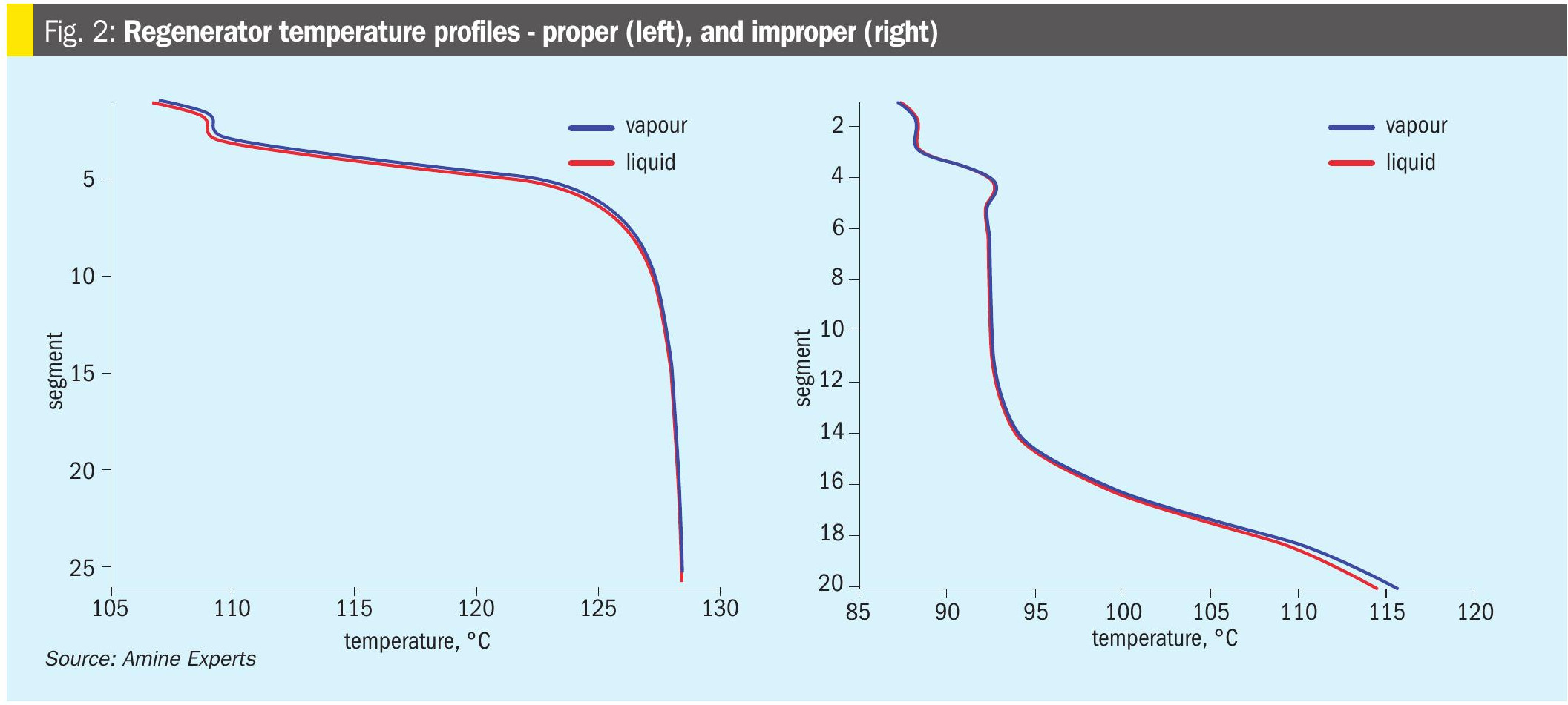
Examples of both proper and improper regenerator temperature profiles are shown in Fig. 2:
Operators can determine the correct amount of heat medium to the reboiler using a combination of parameters:
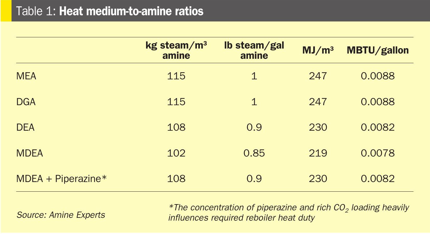
Heat medium-to-amine ratio: The required ratio varies from plant to plant, but good starting points for fresh amine systems are listed in Table 1. A variety of units is displayed.
Overhead temperature: In conjunction with the pressure of the regenerator overhead, the temperature determines the water content, which in turn determines the “stripping ratio”, or the ratio of water to acid gas leaving the stripper tower (in moles). Most amines require a stripping ratio of at least 1, and some up to 4. This generally equates to a regenerator overhead temperature of 100ºC or higher although, like with any aspect of amine plant operation, there are plenty of exceptions. The desired stripping ratio for the amine should be used to determine the target overhead temperature. In general, the recommended minimum stripping ratio for each amine is:
- MEA: 4
- DGA: 3
- DEA: 1.8
- MDEA: 0.9 – 1.3 (very plant-specific)
• MDEA + piperazine: 0.9 – 1.5 (depending on piperazine concentration)
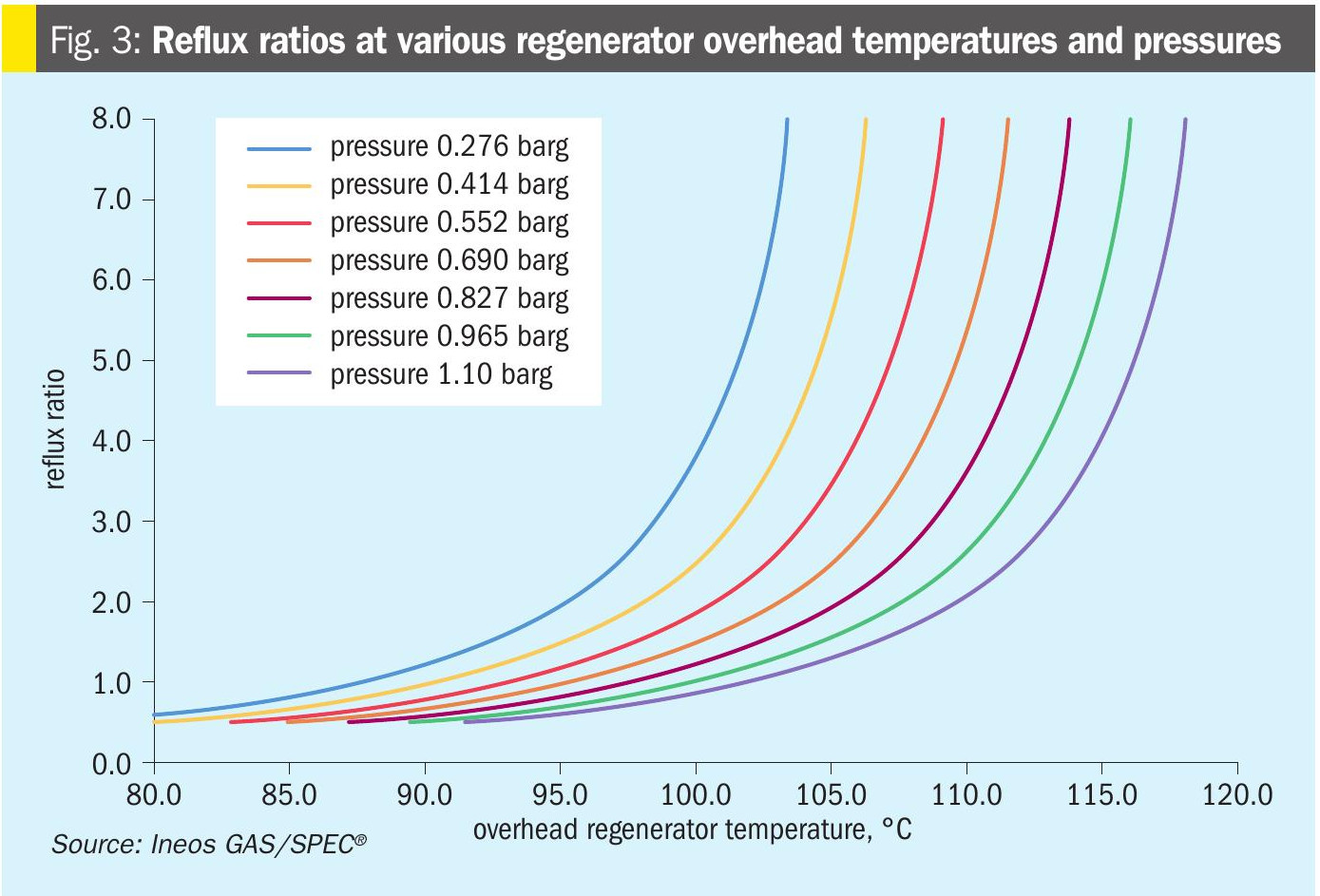
Ineos GAS/SPEC® has developed a handy cheat sheet which provides good estimates for determining the correct overhead temperature at various regenerator pressures, shown in Fig. 3.
Ratio of reflux-to-amine flow: An “old school” approach to amine regeneration is to increase heat duty to the reboiler until a certain flow of reflux water is achieved. This was done in the days before a glance at a DCS screen could tell the operator the regenerator overhead temperature. Most of the older amine plants were MEA, where the rule of thumb was for the reflux flow to equal 10% of the amine flow. Different amines have different required reflux-to-amine flow ratios:
- MEA: 10%
- DGA: 7%
- DEA: 5%
- MDEA: 3-4%
• MDEA + piperazine: 3-5%
Lean loading: This is the least important parameter of setting regenerator conditions. If the first three parameters (heat medium setpoint, overhead temperature, reflux flow) are all correct, the amine will be well enough regenerated that the risk of corrosion is mitigated. The problem with lean loading is that the value is largely affected not only by reboiler duty but also by the heat stable amine salt (HSAS) concentration. The strong HSAS acids drive out the weaker H2S and CO2, so amines with even a small amount (0.5 wt-%or greater) of heat stable salts will, by default, have a very low lean loading. Lean loading measurements are not necessarily useful for setting operating parameters but can indicate problems in the system. For example, a higher-than-expected lean loading can mean the amine is contaminated with a strong base (usually sodium) or there is channelling in the regenerator.
Reasons for amine carryover
Amine can carry-over into the reflux system, and potentially with the acid gas, for several reasons:
• Foaming: When amine is in a foam state, the foam travels upwards, growing in height until it carries over the top of the tower.
• Flooding: If more amine is pumped into the regenerator than can flow down, it will flow up instead. Fouling of the tower internals dramatically increases the likelihood of this scenario.
• Entrainment: An excess amount of upward vapour traffic can lift amine up and out the top of the tower.
• Design deficiencies: Towers designed without reflux trays, or where there is only a small disengaging space between where the rich amine enters and the steam leaves are much more prone to amine carry-over. Towers where the trays are too close together also run higher risks of amine entrainment.
• Operations: Not understanding symptoms of the above problems will allow for a small problem to become a big problem. Carry-over generally does not happen immediately and without warning; proper understanding of the chemistry of amine and reflux water along with education regarding the values on the DCS screen will prevent all but the most extreme examples of unexpected upsets.
Foaming
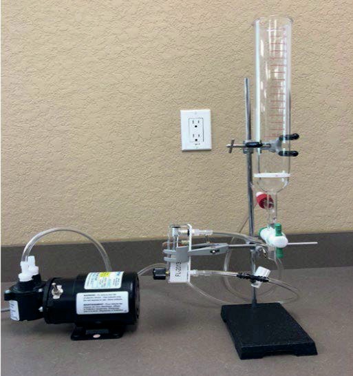
The most common reason for amine loss from a regenerator is foaming. Foaming is when the bubbles formed in the amine do not ‘pop’. The foam builds on top of the amine level either on the trays or on top of a section of packing until it flows out of the top of the tower with the steam. Amine and reflux samples should be regularly foam tested by bubbling gas through a bubbling device located at the bottom of an amine sample. The foam height should be measured, as well as the length of time it takes for the foam to disappear after the bubbling stops. These two parameters are referred to as foaming tendency and foaming stability. The amine foam test apparatus used by Amine Experts is shown in Fig. 4.
Trayed columns are far more at risk of foaming compared to those that are packed. Nonetheless, both styles of regenerator can foam. The main symptoms of regenerator foaming are:
- increasing differential pressure;
• loss of bottoms liquid level (or reboiler level depending on the design);
• increasing liquid level in the overhead accumulator.
The order in which these symptoms occur can be used to determine where in the tower the foaming originated and, therefore, how to troubleshoot it before it results in excessive carryover.
Foaming originates in the bottom: If the first symptom is a loss of bottoms or reboiler level, followed by an increase in dP, and finally an increase in overhead accumulator level, this indicates the foaming originated on the bottom tray, or possibly within the reboiler itself. Because the amine is being converted to foam and is now travelling upwards, it is starving the bottoms section of liquid. Either the liquid level will drop, or in the case of regenerators with level control valves on the lean amine outlet, the level control valve will start to close. The lower section of a regenerator is the hottest area of the amine plant, so for a foam-promoting contaminant to reach this area it is either very stable (non-volatile) or the overall temperature of the regenerator column is too low to have vaporised the contaminant higher up in the tower.
Foaming originates in the top: If the only symptom is amine carryover, with little or no change in dP, and a delayed effect on bottoms level, this indicates the foaming started very high up in the tower. This is the most dangerous type of foaming, as there is little warning to the operator. Either the amine was contaminated and ready to foam the moment it was agitated upon entry to the regenerator, or it blended with contaminated reflux water, and the combined amine/reflux blend then foamed.
Foaming troubleshooting
Before developing a foaming-mitigation plan, foam tests should be performed on the reflux water as well as the lean and rich amine. The temperature profile of the regenerator should also be known, which is best done by using a simulation program. Foam test results:
• Rich amine: This sample should be taken after the flash tank (if the system has one), before the lean/rich exchanger. If the sample’s foaming tendency or stability is high, the flash tank may require optimisation. Flash tanks are designed to remove gas and liquid phase hydrocarbons, which are often foam-promotors. Gas-phase hydrocarbons will flash off if the tank pressure is low enough. The flash tank pressure should be only high enough to “push” the gas to its destination and the rich amine into the regenerator (assuming the system does not have rich amine pumps). The amount of pressure needed to push rich amine to the regenerator can be determined by the flash tank level control valve opening; it should be 60-70% open. If it is less than this, the tank pressure can be lowered, which will increase the hydrocarbon removal efficiency.
Rich amine can also be contaminated by suspended solids, which also exacerbate foaming by increasing the foam stability. Rich amine filters can go a long way to reducing foaming problems in regenerators by removing these particles. In the lab, foam test the rich amine then filter the sample and re-do the foam test to note if there is any improvement.
• Lean amine: Lean amine should be sampled after the lean/rich exchanger and before the activated carbon bed. If the sample exhibits high foaming tendency, this indicates the foam-promoting contaminant has gotten through the regenerator/reboiler. This can normally be solved by increasing the steam flow through the regenerator, raising the temperature of the column. If not, the activated carbon should be used to remove the contaminant, which is likely non-volatile and may be a heavy hydrocarbon.
• Reflux water: If the sample is foamy, this is a good sign as it means the regenerator is working to drive contaminants out of the amine. The operator should then purge as much reflux water as possible, ideally until the samples show low foaming tendency. If the sample is not foamy, however, yet the lean amine is and/or there are symptoms of foaming in the regenerator then the steam flow through the tower should be increased for several hours, then the reflux water re-sampled. If the foaming tendency increases after raising the steam flow, it means the regenerator is now vaporising the contaminant, and the reflux should then be purged.
If the reboiler duty is already more than adequate, and the regenerator temperature profile is correct, it means the foam promotor is not volatile. Injection of a tested, proven antifoam will collapse the foam back to liquid, carrying the contaminant with the lean amine. An activated carbon bed can then be used to remove the contaminant.
In summary, if the foaming is suspected to be originating in the bottom or middle of the regenerator, increase the ratio of heat medium (steam, hot oil, glycol, etc) to the reboiler in relation to the amine flow. The contaminant will hopefully be vaporised higher up in the tower and not cause foaming.
If the foaming is originating in the very top of the regenerator, improve the operation of the flash tank, and investigate if installing rich amine filters will help.
Once the contaminants have been vaporised, they tend to concentrate in the reflux water, which should be purged.
Until the amine is free of foam-promoting contaminants, antifoam should be injected, either into the rich amine or the reflux water, to prevent amine carryover. Antifoam mobilises the contaminant into the lean amine, where it should be removed by activated carbon.
Flooding
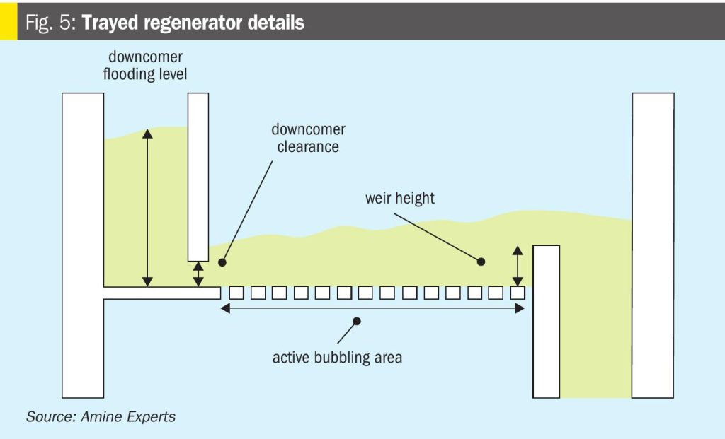
Knowing the hydraulic limitations of the regenerator is important to prevent flooding of the tower. Trayed towers are more prone to flooding than packed, because the amine level in the downcomer can build up if the circulation is too high. The height of the liquid in the downcomer should not exceed 85% of the downcomer’s volume. All commercial simulators will predict the downcomer flooding if accurate tray information is entered into the program, including the tray diameter, active area, weir height and downcomer clearance (shown in Fig. 5). If this information is not known, then the current flows should be compared to the design flows; as long as the flows do not exceed 120% of the design, there should not be flooding as most towers are designed to have 70% downcomer flood.

Flooding can also occur, even if flows are within the hydraulic limits, if there is fouling in the tower. Trays can foul inside the downcomers, eventually blocking the flow through the downcomer clearance. Packing is more likely to foul than trays, so rich amine cleanliness is therefore more important when packing is used. Fouling is normally detected by gamma scanning. The symptoms of flooding are similar to fouling, with a few key exceptions:
• adding (a tested, proven) antifoam does not stop the carryover or lower the dP;
• the carryover is continuous regardless of steam flow through the tower.
Unfortunately, there is no good quick fix for fouling. The unit should be shut down and cleaned.
Entrainment
If the steam flow is excessive, amine will be physically carried over by the high vapour flow. Similar to troubleshooting possible flooding, the design value of the steam flow should be known, or at least the design heat medium flow to the reboiler. The steam flow in the tower (or heat medium flow to the reboiler) should be within 120% of design. Alternatively, use an amine simulator to perform the calculations. The vapour flow through the tower is measured by “jet flood”. At jet flood levels of above 85%, droplets of amine will start to be carried upwards with the steam, and entrainment losses become possible. Amine losses by entrainment manifest as a steady, consistent but low level of amine carried into the reflux system. The reflux water will therefore contain higher-thannormal levels of amine which can be measured by a digital refractometer and inferred by pH measurements.
In trayed towers, the tray spacing can affect the chances of entrainment. Trays are typically spaced 610 mm apart, however in some cases the spacing is lower, for example 450 mm. The closer the trays are together, the higher the risk of entrainment since the amine does not have to carry the amine up as high before it will be lifted to the tray above. The type of tray also plays a role; sieve trays allow the steam to flow straight up compared to most valve trays where the steam enters each tray horizontally. Towers with sieve trays are, therefore, especially prone to entrainment. The plant engineer should be aware of the tower internals, which can heavily influence the risk of entrainment.
Entrainment does not normally result in high enough volumes of loss that the amine would get all the way to the SRU, but it may be a contributor if other carryover mechanisms are also occurring. Because foaming is a combination of contamination and agitation, if the jet flood is so high that entrainment is occurring, it also means the amine is being highly agitated and foaming is much more likely even if the level of contamination is somewhat low.
Design deficiencies
The design of the tower certainly plays a role in determining the risk of amine carry-over. Some design parameters that should be paid attention to when troubleshooting amine carryover are:
• Trays too close together (610 mm spacing preferred, 450 mm minimum).
• Tray type (sieve trays are more prone to entrainment due to high vertical vapour velocity compared to valve trays, where the gas is forced to enter the trays horizontally).
• Packing size too small.
• The amine and steam are forced through smaller areas, increasing vapour velocity.
• Smaller packing fouls easier than larger.
• 38 to 50 mm (1.5 to 2”) packing size is normally appropriate.
• No reflux trays
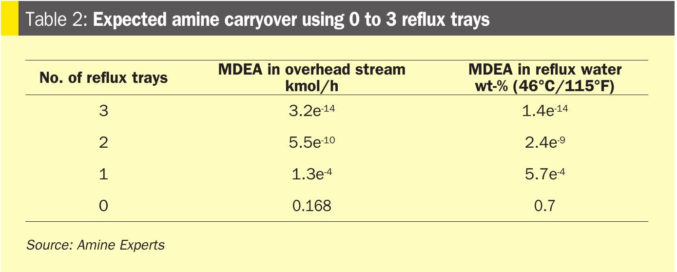
• Some tower designs do not include reflux trays. Instead, the reflux is returned to the system either to the flash drum or it combines with the rich amine and the two liquids enter the tower together. There are pros and cons to all designs, but certainly reflux trays will generally act as “water wash” trays and minimise amine carryover from entrainment or vaporisation. If the reflux water is contaminated, however, it will promote foaming in the top of the regenerator and make carryover worse. Reflux trays, in general, will reduce amine carryover with steam, but the reflux water must be clean so as not to promote foaming.Simulations can be used to estimate the amount of amine in reflux water; for example, in a regenerator operating with overhead conditions of 104°C and 83 kPag (220°F, 12 psig) Table 2 lists the expected amine carryover with the steam.
• No reflux water purge
• Reflux water often contains foam-promoting contaminants and should have a mechanism to purge all or part of the flow so that these contaminants can be removed from the system. Without a purge, the contaminants will be pumped back into the amine, which can cause foaming and amine carryover.
Operations
Operators must understand the values on the DCS screen of the amine regenerator and recognise when carryover potential exists. Many large carryover problems can be stopped before they start by diligent board operators. At a minimum, these values must be monitored, especially if the numbers are changing:
• Reflux accumulator level: If this level is rising, it almost certainly means amine carryover is occurring. Ideally this would have been prevented by monitoring other parameters listed below. At this point immediate action must be taken such as antifoam addition or even cutting heat medium to the reboiler, or further carryover to the SRU is very possible.
• In Amine Experts’ experience, if the acid gas line fills with amine, much of it will be caught in the acid gas knockout (KO) drum just upstream of the SRU. Although this protects the SRU, liquid flowing through the acid gas line will carry a lot of debris into the KO drum. It can even block the vessel drain. If the KO drum level remains high even with the drain valve open, check it right away for blockage, or the drum will fill and spill directly into the reaction furnace!
• Overhead temperature: The two main causes of large-volume amine carryover are foaming and flooding. Both will impact the overhead temperature but in different ways. Flooding tends to condense more steam since there’s a large volume of liquid the steam is fighting through. The overhead temperature will, therefore, decrease. On the other hand, if the regenerator is suffering from foaming, the steam will not be condensed as efficiently since there is not significant heat transfer between steam and foam. In this case the overhead temperature will increase. Sudden changes in the overhead temperature, either up or down, should be flagged and investigated immediately.
• Differential pressure: Depending on what and where the problem is, an increase in differential pressure (dP) may be the earliest warning sign of amine carryover. If the dP is rising but there are no other changes (no amine carryover, no loss of bottoms level), likely the foam or flooding is starting in the middle/bottom of the column and climbing upwards.
• Antifoam should be added to either the rich amine or the reflux streams; observe if the dP lowers back down. If so, foaming was to blame, and it was caught before it resulted in carryover. To prevent this from recurring, increase the steam flow through the tower and vaporise the foam-promoting contaminant so it does not reach the lower section of the tower where steam flow and, therefore, agitation of the amine is higher.
– The reflux should then be purged, since the vaporised contaminants will build up in the water.
• If antifoam has no effect, heat medium to the reboiler may need to be reduced. This should be as temporary and to as small of a degree as possible, since a lack of steam flow will allow acid gases into the reboiler which is very corrosive. But it is better than carrying amine over towards the SRU. However, this is a short-term fix and the root cause of the high dP must still be determined. A gamma scan may be necessary if fouling is suspected.
• Bottoms liquid level: A loss of bottoms level can indicate amine is being “hung up” in the tower, starving the bottom of the regenerator. To make sure amine is being continuously fed to the reboiler, check the flash tank level control valve is not 100% open – if it is, increase the flash tank pressure and investigate if possibly the rich amine filters or lean/ rich exchanger are plugged.
If amine is flowing into the column but not moving downwards, inject anti-foam immediately, before there is a level increase in the reflux accumulator.
If a loss of bottoms level is the first indication of problems, it means the amine is making its way most of the way down the tower before running into difficulty (any other scenario and the dP or amine carryover would happen first). This usually means there is not enough steam traffic in the tower and contaminants are able to flow too far downward. Increase steam flow to prevent the situation from recurring.
• Lean/rich amine and reflux water foam tests: Operations has a vested interest in the foaming tendency of the amine and reflux water samples. If the lean or rich amine, or reflux water foaming tendency is increasing, it often means problems are building in the regenerator. In plants struggling with amine carryover from the regenerator, foam testing of these three samples should be performed regularly.